

Basic_Electrical_Engineering_4th_edition
.pdf
NETWORK THEORY |
1 25 |
2.4LOOP ANALYSIS
Let us consider a few application ofKVL in terms of loop or mesh analysis.
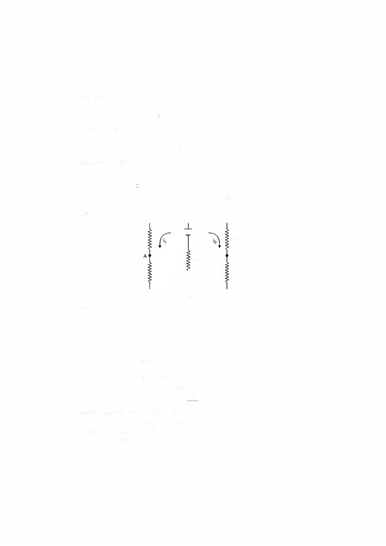
Example 2.1. Determine the current in all the branches of the network using loop analysis.
Fig. E2.1
Solution: Let the currents i1 and i2 be flowing in the two loops as shown. It is to be noted that the direction ofthe currents is arbitrary. However, depending upon the values of i1 and i2 thus obtained we can ascertain the direction. If they are coming out to be positive, the directions remain as shown in the figure, otherwise one with negative value, the direction of this current is reversed.
Writing loop equation for loop 1 |
|
|
|
|
|
|
|
|
|
4il + 2(il + i2) = 30 |
|
|
|
|
|
||
or |
6i, + 2i2 |
= 30 |
|
|
|
|
...(1) |
|
Loop 2 |
4i + 2(il + i) |
= |
40 |
|
|
|
|
|
or |
2il + 6i2 = 40 |
|
|
|
|
...(2) |
||
Multiplying equation (2) by 3 and subtracting equation (1) from this we have |
||||||||
|
16i2l |
= |
90 |
|
|
i2 |
= 5.625 A |
|
|
= |
or |
|
|||||
Hence |
2il + 6 x 5.625 |
= 40 |
|
|
|
|
|
|
|
2i |
|
40 |
|
33.75 |
|
||
or |
2i1 = 6.25, i1 = 3.125 A Ans. |
|||||||
Hence |
i3 = i1 + i2 = 5.62 + 3.125 |
= 8.75 A |
|
|
|
|||
The current through 2 Q branch is 8.75 A. |
|
|
|
|||||
Since both the currents i15and i2 |
are found to be positive hence the directions shown in |
|||||||
Fig. E2.1 is correct. |
current for |
|
as shown in Fig. E2.l.1 shown here |
|||||
Suppose we take the direction of |
|
|
- |
|
|
i2 |
|
|
Fig. E2.1.1

1 26 |
|
|
|
|
ELECTRICAL ENGINEERING |
|
For loop 1 |
4i1 + 2(i1 - i2) = 30 |
|
||
|
|
|
|||
or |
|
|
6il - 2i2 = 30 |
...(1) |
|
|
|
4i2 + 2(i2 - il) + 40 = 0 |
|
||
or |
ihy22 = - 5.625 |
- 2il + 6i2 = - 40 |
...(2) |
||
|
= |
|
|
||
|
Multiply equation (2) |
3 and add to equation (1) |
|
||
|
16i |
= - 120 + 30 |
- 90 |
|
|
and |
- 2il - 33.75 = - 40 |
|
|
|
|
or |
- 2il = - 6.25 |
|
|
|
|
or |
i1 = 3.125 A |
|
|
|
|
|
We find the i2 is coming out to be negative and hence the direction of current in loop 2 |
||||
should be opposite to what is shown in Fig. E2.1.1. |
|
||||
|
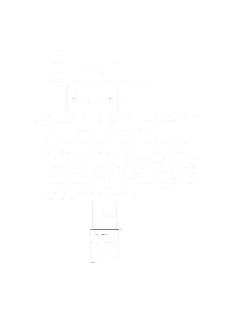
Example 2.2. Determine the current in each branch of the network shown in Fig. E2.2 |
||||
using loop analysis. |
2 Q |
|
7 Q |
3 Q |
|
|
|
1 0 |
|||
|
1 1 v - = - 7 |
7 2 0 |
7 - = - 31 v |
||
|
|
i1 |
|
i2 |
i3 |
Fig. E2.2
Solution: Since there are three loops, three independent loop equations are required to solve the network. Suppose the directions of currents are as shown in Fig. E2.2. Writing equa tions for the three loops
or
Loop I |
|
|
2i1 + l(i1 - i2) = 1 1 |
|||
|
|
|
|
3il - i2 = 1 1 |
||
Loop II |
7i2 + 2(i2 - i3) + (i2 - i1)1 = 0 |
|||||
|
|
- il + l0i2 - 2i3 = 0 |
||||
Loop III |
|
|
3i3 + 2(i3 - i2) = 13 |
|||
|
|
|
- 2i2 + 5i3 = 13 |
|||
In matrix form the equations can be written as |
||||||
|
-! - |
= |
I:iI |
|||
|
= |
3 |
- 1 |
0 |
|
|
Hence det [A] |
- 1 |
10 |
- 2 |
|
||
|
|
0 |
- 2 |
5 |
|
|
|
= 3(50 - 4) + 1(- 5) = 133 |
|||||
...(1) ...(2) ...(3)


NETWORK THEORY |
1 33 |
At node B - VA12 |
|
(-1:_ |
|
-1:_ |
|
|
I) |
VB - VJ2 = 0 |
|
|
|||||||||||
|
|
|
|
|
2 |
|
|
2 |
|
|
2 |
|
|
( |
|
|
|
|
|
|
|
|
|
|
|
+O.V |
+ |
|
- |
|
|
|
1 |
|
|
1 |
= O |
|
|
||||
At node |
|
|
|
VB |
|
V:c |
|
|
|
|
|
|
|||||||||
|
|
|
|
+ |
+ |
|
|
- |
+ |
- |
|
|
|||||||||
|
|
|
|
|
A |
- |
|
2 |
|
|
|
|
2 |
|
2) |
|
|
|
|||
|
|
|
|
|
|
|
|
|
|
|
|
|
|
|
|
|
|||||
These |
equations can be written in matrix form as follows: |
|
|
||||||||||||||||||
|
C |
|
|
1 |
|
|
|
|
|
|
|
|
|
|
|
|
|
|
|
|
|
|
|
1 |
1 |
|
|
|
|
|
|
1 |
|
|
|
|
|
|
|
|
|
|
|
|
|
-2 |
+ -21+ - |
1 |
|
- |
2-2+ |
|
|
|
|
01 |
|
|
|
|
|||||
|
|
|
- |
2 |
- |
1 |
1 |
|
|
|
|
|
|
|
|||||||
|
|
|
|
|
- |
- |
|
|
|
|
|
|
|
|
|||||||
|
|
|
02 |
|
2 |
|
+- |
-1 |
2 |
|
|
1 |
21 |
|
|
|
|||||
|
|
|
|
|
|
|
|
|
|
|
2 |
|
|
|
2 |
|
|
2 |
|
|
|
Here the first matrix is known as nodal admittance matrix and is denoted by |
|
and the |
|||||||||||||||||||
two column matrices are known as nodal |
voltage and nodal current matrices denoted by and |
||||||||||||||||||||
- + - |
mHl |
Y |
V |
||||||||||||||||||
I respectively. |
|
|
|
|
|
|
|
|
|
|
|
|
|
|
|
|
|
|
|||
Hence, the above matrices can be written in compact form as |
|
...(2.22) |
|||||||||||||||||||
|
|
|
|
|
|
YV=I |
|
|
|
|
|
|
|
|
|
||||||
It can be seen that the nodal admittance matrix can be written simply by looking at the interconnections of the network using the following procedure:
(i)The diagonal element of each node is the sum of the admittances connected to it.
(ii)The off diagonal element is the negative admittance between the nodes. If there is
no connection between the two nodes, the entry in the off-diagonal for both the nodes is zero i.e. if node i is not connected to the node j, then Yij = Y;i = 0. In general every node will not be connected to all other nodes in the network and hence nor mally nodal admittance matrix is a highly sparse matrix i.e. it will have very small
number ofnon-zero elements. In fact, in a large network consisting of say 1 00 nodes, these non zero elements would be as small as 2% of the total elements.
We come back to original problem offinding out |
VAB |
|||||
Using Cramer's rule |
|
5 |
--1 |
0 |
|
|
|
|
0 |
2 |
1 |
|
|
|
|
|
3 |
|
|
|
|
|
|
--2 |
2 |
|
5 |
|
vA = |
0 |
1 |
1 |
5 x |
- |
|
|
2 |
0 |
4 |
||
|
|
3 |
1 |
-8 |
||
|
|
|
13 |
|||
|
|
2 |
2 |
1 |
|
|
|
|
1 |
3 |
|
|
|
Therefore, |
V |
= |
13 |
20volts-221 |
21 |
__ |
A |
|
50 |
||||
|
|
|
|
|
|