Basic_Electrical_Engineering_4th_edition
.pdf


CHAPTER
1A-C Circuits
1 .1 INTRODUCTION
Network theory, in general, deals into three components, the network, usually consisting ofa suitable combination of R, L and C, the source and the response. Mostly, it is desirable that whatever is the waveform ofthe source, same waveform should appear in the response (Excep tions to be ignored). We havevarious waveforms viz. square, triangular, trapezoidal, sinusoidal etc. Out of all these, if the circuit has resistance only, one can use any ofthe waveforms men tioned above and the response (v-i relation) will have the same waveform as the excitation (source). However, with L and C as the element, it is only sinusoidal waveform which satisfies the requirement ofidentical waveforms for source and response. Ifthe source is voltage source the current through the inductor is proportional to the integral ofthe voltage wave and for the capacitor, it is the derivative ofthe voltage wave. It is a very useful and important property of sine waves that both it's derivative and integrals are also sinusoidal. The basis for standardi zation on the sine wave thus comes from both physics and calculus. Also, it is very easy to generate the sine waves using rotating machines and transmit and distribute electric energy using transformers. We next illustrate that a uniform circular motion or simple harmonic motion is a sinusoidal variation.
Sine wave is the basic waveform of a.c. circuit theory and it is necessary to learn how to handle such waves.
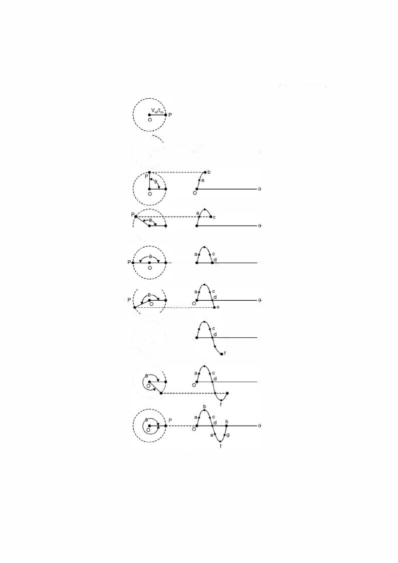
Let us relate a uniform circular motion or rotation to a sinusoidal wave form. We con sider a rotating voltage/current phasor that has a length Vm!Im and is coincident along x-axis Fig. 1.1. We start counting time and rotate the phasor anti-clockwise and at various instant of time we take the projection of the rotating phasor along y-axis.
At t = 0, the projection is zero and hence we plot a point on the right hand side along t(9) axis. After certain time say t the phasor rotates through an angle 8 and there is some finite
projection along y-axis, mark this on the right hand side along t(9) axis as shown in Fig. 1.1. As we rotate the phasor further when 8 = 90° the value of the projection is ViJim. Mark it on
the right hand side along t(8) axis as shown. Rotate phasor further and obtain the projection along y-axis, the projections decreases beyond 90° and continues to be along + y axis till 8 = 180° when projection is zero.
49

A-C CIRCUITS |
|
|
|
|
|
51 |
Similarly if we rotate the phasor further through 27t radian or |
|
|
or one cycle, we |
|||
obtain a complete sine wave as shown in Fig. |
|
Thus, ifthe speed ofrotation is revolutions/ |
||||
1.1. |
|
3 |
60° |
f |
|
|
sec the phasor has a frequency offhertz (Hz). Hence the angular velocity is c o =27t f rad/sec.
If the instantaneous value of time at any instant of rotation is t seconds the total angle in radians from time zero upto that point is
2nft = rot
The concept ofrotating phasor is a function oftime, we may substitute 2nft or wt for 8 in the equation.
V = Vm sin 8
and now therefore, the instantaneous voltage in terms of time is |
|
|
|
|
|
...(1.1) |
|||||||||||
|
|
|
|
|
|
v = vm sin 2nft = vm sin wt |
|
|
|
|
|
||||||
when equation 1.1 is used, the axis of the waveform is not 8 but time t. |
|
|
|
||||||||||||||
1 .2 PHASE |
|
|
|
|
|
|
|
|
|
|
|
|
|
|
|
|
|
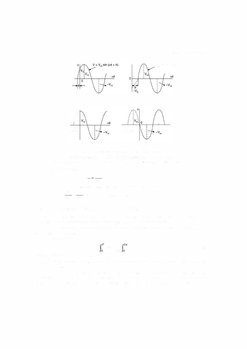
A sinusoidal waveform having a displacement of 8 to the left is shown in Fig. |
1.2(a) |
which |
|||||||||||||||
means that at t |
= |
|
the phasor has an initial displacement of 8 in |
|
|
|
|
|
|||||||||
|
|
|
|
|
|
|
|
|
|
|
counterclockwise direction. |
||||||
Therefore, the |
initial instantaneous value ofvoltage/current at time |
|
= is |
|
|
||||||||||||
|
|
0 |
|
|
|
|
|
|
|
|
|
t |
|
0 |
|
|
|
V = V,n sin 8 putting wt = |
|
This shift of the waveform is called a phase displacement |
|||||||||||||||
and the angle 8 is called phase |
angle. Fig. |
|
(b-d) |
show different phase displacements ofthe |
|||||||||||||
|
0. |
|
|
|
|
|
|
|
|
|
|
||||||
same sine wave. The sine wave at 'a' is |
said to be leading the wave at |
'b' |
as |
|
|
||||||||||||
|
1.2 |
|
|
|
|
|
|
|
|||||||||
|
|
|
|
Va = Vm sin (cot + 8) and at b |
|
|
|
|
|
|
|||||||
|
|
|
|
vb |
= |
vm sin (wt -8) |
|
|
|
|
|
|
|
||||
|
|
|
|
|
|
|
|
|
|
|
|
||||||
Example 1.1. The equation for a voltage wave is v = 0.02 sin (4000t + 30°). Find the frequency, the instantaneous voltage when t = 320 µ sec. What is the time represented by 30° phase difference?
Solution: The general expression for voltage is given as
|
V = Vm sin (2rcft + 8) |
|
|
|
|
||
here |
2nf= 4000 |
or f= 2;4000- = 637 Hz. |
|
||||
When |
v = |
t = 320µ. sec. |
-6 |
x |
---180 |
;-) |
|
|
|
0.02 |
. (4000 x 320 x 10 |
|
+ |
30° |
|
v= 0.02 sin (73.3 + 30)
=0.02 sin (103.3)
=0.0195 volt