

Basic_Electrical_Engineering_4th_edition
.pdfx
A large number of problems have been solved to help understand the theory. At the end of each chapter unsolved problems with their answers have been suggested for further prac tice. At the end, a large number of objective type questions have been added to help the reader to test himself.
Any constructive suggestion for the improvement of the book will be gratefully acknowledged.
Last but not the least, I with to express my gratitude to mywife Usha, daughter Meenu and son Sandeep for their patience and encouragement during the preparation of the book.
-C.L. Wadhwa

|
CONTENTS |
Preface to the Fourth Edition |
....................................................................................... (vii) |
Preface to the First Edition ........................................................................................... |
(ix) |
DC CIRCUITS . . . . . . . . . . . . . . . . . . . . . . . . . . . . . . . . . . . . . . . . . . . . . . . . . 1
i.1 i.2 i.3 i.4
i.5
i.6 i.7 i.8 i.9 i.10
International System of Units ................................................................................... |
|
|
1 |
|
Circuit .......................................................................................................................... |
|
|
3 |
|
Electric Current . |
|
. . |
|
|
Electric Potential ........................................................................................................ |
|
|
4 |
|
Resistance ................................................................................................................... |
|
|
6 |
|
i.5.1 |
Conductivity and Conductance |
|
|
3 |
. |
. . |
7 |
||
Power |
|
|
|
8 |
Energy ......................................................................................................................... |
|
|
8 |
|
Ohm's Law ................................................................................................................... . . . . . . . . . . . . . . . . . . . . . . . . . . . . . . . . . . . . . . . . . . . . . . . . . . . . . . . . . . . . . . . . . . . . |
. . . . . . . . . . . . . . . |
. . . . . . . . . . . . . . . . . . |
. 8 |
|
Kirchhoffs Laws ....................................................................................................... |
|
|
11 |
|
Series Circuits ........................................................................................................... |
|
|
13 |
|
i.10.1 |
Parallel Circuits .............................................................................................. . . . . . . . . . . . . . . . . . . . . . . . . . . . . . . . . . . |
. . . . . . . . . . . . . . |
. . . . . . . . . . . . . . . . . . . |
15 |
i.10.2 |
Series. . . . . . . . . . . Parallel. . . . . . . . . . . . . . .Circuits. . . . . . . . . . . . . . ................................................................................... . . . . . . . . . . . . . . . . . . . . . . . . . . . . . . . . . . . . . . . . . . . . . |
. . . . . . . . . . . . . . . |
. . . . . . . . . . . . . . . . . . . . . |
18 |
ii |
ELECTROMAGNETIC INDUCTION . . . . . . . . . . . . . . . . . . . . . . . . . . . . . . . . |
29 |
|
ii.1 |
Introduction .............................................................................................................. |
29 |
|
ii.2 |
Faraday's Laws of Electromagnetic Induction....................................................... |
29 |
|
|
ii.3 |
Lenz's Lavv................................................................................................................. |
30 |
|
ii.4 |
Laws of Electromagnetic Forces .............................................................................. |
30 |
|
|
ii.4.1 Fleming's Left Hand Rule ............................................................................. |
32 |
|
|
ii.4.2 Flemings Right Hand Rule ........................................................................... |
33 |
|
ii.5 |
Dynamically Induced EMF (Generator or Motional EMF) ................................... |
33 |
|
|
ii.5.1 Statically Induced EMF or Transformer EMF............................................ |
34 |
|
ii.6 |
Self Inductance ......................................................................................................... |
35 |
|
ii.7 |
Mutual Inductance ................................................................................................... |
36 |
|
ii.8 |
Hysteresis Loss ......................................................................................................... |
38 |
|
ii.9 |
Eddy Current Loss ................................................................................................... |
40 |
1 A.C. ClRCUITS . . . . . . . . . . . . . . . . . . . . . . . . . . . . . . . . . . . . . . . . . . . . . . . |
49 |
||
|
1.1 |
Introduction .............................................................................................................. |
49 |
|
1.2 |
Phase ......................................................................................................................... |
51 |
|
1.3 |
The Average Value of a Waveform .......................................................................... |
52 |
|
1.4 |
The Effective or RMS Value of a Wave ................................................................... |
54 |
xi

|
|
1.4.1 |
Form Factor |
|
|
|
|
|
|
|
|
xii |
|
|
|
|
|
|
|
|
|
|
|
|
|
|
|
|
|
|
|
|
|
55 |
|||||||
|
1.5 |
1.4.2 |
Peak Factor or Crest Factor |
|
|
|
|
|
|
|
|
|
|
|
|
|
|
|
|
|
|
|
|
|
|
|
56 |
||||||||||||||
|
Phasor Diagram . |
. |
..... |
|
. |
|
|
|
. . . . ... . . . . . . . ....... . . . . ...... . . |
. . . . . .. . . . . . |
|
56 |
|||||||||||||||||||||||||||||
|
|
1.5.1 |
Phasor Algebra |
|
|
|
|
|
|
|
|
|
|
|
|
|
|
Voltage . |
|
|
|
. . . . . . . . . . |
|
|
|
|
|
57 |
|||||||||||||
|
1.6 |
Resistance Connected .Across. . . . . a.Sinusoidal. . . . |
|
|
|
|
|
|
|
|
57 |
||||||||||||||||||||||||||||||
|
|
1.6.11 |
Inductor Across Sinusoidal Source. . . . . . . . . . . .. . .. .. .. ..... . ..... .. . .... .. .. .. .. . .. . .. ..... . .. ..... . . .. |
. .... .... .. ... ... ... .... .... .... . ... ..... ... ... |
. |
. |
.. |
. |
60 |
||||||||||||||||||||||||||||||||
|
|
|
|
|
|
|
58 |
||||||||||||||||||||||||||||||||||
|
|
1.6.2 |
Capacitor Connected. . . . . . . . . . . . . . . .Across. . . . . . . . . . .Sinusoidal. . . . . . . . . . . . . . . . . . . .Source. . . . . . . . . . |
. . . . |
. . . . |
. . . |
. |
. . . . . . . |
... ... .. . . . . .. . ... . . |
. . . . |
. . ... .. |
59 |
|||||||||||||||||||||||||||||
|
|
.6.3 Series R-L Circuit Connected to Sinusoidal Source |
|
|
|
|
|
||||||||||||||||||||||||||||||||||
|
1.9 |
1.6.4 |
RC Series Circuit. . . |
Connected. . . . |
to. . Sinusoidal. . . |
Source. . . . |
|
|
61 |
||||||||||||||||||||||||||||||||
|
Series Resonance .... . .. . . . . .. . . ... . . . .... .. . . . . . . .... . ... .. |
. ... ... ... . . . . . . ..... . . . . . ... ..... . . ... ... |
70 |
||||||||||||||||||||||||||||||||||||||
|
|
1.6.5 |
R-L-C Series Circuit. . . . . . . . . . .Connected. . . . . . . . . . . . . . . .to. . . . .Sinusoidal. . . . . . . . . . . . . . . . . . Source. . . . . . . . . . . . . |
. |
. . . . . . . |
. . . . . . . . . . . . . . . |
. . . . |
. |
|
. |
. |
. |
64 |
||||||||||||||||||||||||||||
|
1.7 |
1.9.1 |
Quality Factor Q |
. |
. |
.... |
. . |
. |
. |
|
|
|
. ..... |
|
|
..... . . ... . . . .. . ... ....... . . . . ... ... ...... . . . ... ... ... ... .... . ... |
74 |
||||||||||||||||||||||||
|
Parallel R-L Circuit Across Sinusoidal Supply |
|
. . . . . |
. . . . |
. . . . . |
. . |
. |
... .. ... .. ... .. ... .. ... .. ... .. ..... .. .. .. ... .. ... .. . .... .. . .. . .. .. .. .. |
66 |
||||||||||||||||||||||||||||||||
|
1.10 |
Parallel Resonance. . . . . . . . . |
|
|
|
|
|
. . . . . .. . . . . . .. . .. . .. . . . . . ... .. . . . . . . |
80 |
||||||||||||||||||||||||||||||||
|
|
1.7.1 |
Parallel R-C Circuit Across Sinusoidal. |
Source. . . .. . . . . . |
....... |
. .. .. .. . .. .. . . . . . |
67 |
||||||||||||||||||||||||||||||||||
|
1.11 |
1.7.2 |
Series Parallel Circuits of R, L and C |
|
|
|
|
. . . . |
. . . . . |
. . |
. |
. . . . . . . |
. . . . . . . . . . . . . . . . |
. . . |
. |
. |
|
. . |
|
68 |
|||||||||||||||||||||
|
Magnetic Circuits . . |
|
|
|
|
.. . .. . ... . . .. .. ... . . . . .... .... .... .... ... . .. . .. . .. . .. . ... . .. .... ... . . . . . . . . . ... ... ... ... .... . .. . . . . . |
91 |
||||||||||||||||||||||||||||||||||
|
1.8 |
Resonance |
|
|
|
|
|
|
|
|
|
|
|
|
|
|
|
|
|
|
|
|
|
|
|
|
|
. |
. .. . |
.. . |
.. |
. . . . . ... |
. . . . . . . .. . . . . . . . .. |
. .. . |
.. |
. |
|
.. . |
|
69 |
|
|
|
1.11.2 Leakage Flux. |
|
|
|
. . |
|
. . |
|
|
|
. . |
|
|
|
. . |
|
|
. |
|
. . |
|
. . |
|
. . . . . |
|
. . . |
98 |
|||||||||||||
|
|
1.11.3 Fringing of Flux. .. |
|
.. |
. . |
. . |
. .. . |
|
. .. .. .. . . . . . .. . ... . . . . .. . .... .. . . ..... .. .. . . . . . .... . . |
99 |
|||||||||||||||||||||||||||||||
|
|
1.10.1 Q of Parallel RLC Circuit |
|
|
|
|
|
|
|
|
|
|
|
|
. . |
|
|
. |
|
. . . . . . |
|
|
|
. . |
85 |
||||||||||||||||
|
|
|
|
|
|
|
|
|
|
|
|
|
|
|
|
. . . . . . . . . . . . . . . . . . . . . . . . . . . . . . . . . . . . . . . . . . . . . . . . . . . . . . . . . . . . . . . . . . . . . . . . . . . . . . |
|
||||||||||||||||||||||||
|
|
|
|
|
|
|
. . . . . . . . . . . . . |
|
. . . . . . . . . . . |
|
. . . . . . . . . . |
|
|||||||||||||||||||||||||||||
|
|
1.11.1 Analyses. . . . . . . . .between. . . . . . . . . . . . . . . Magnetic. . . . . . . . . . . . . . . . .and. . . . . . . .Electric. . . . . . . . . . . . . .Circuits. . . . . . . . . . . . . |
.. .. .. . .. . .. .. .. .. .. .. .. .. .. .. .. .. .. .... .... .. .. .. .. .. .. .. . .. . .. .. .. .. .. .. .. |
92 |
|||||||||||||||||||||||||||||||||||||
|
|
|
|
|
|
|
|
. . . . . . . . . . . . . . . . . . . . . . . . . . . . . . . . . . . . . . . . . . . . . . . . . . . . . . . . . . . . . . . . . . . . . . . . . . . . . . . . . . . . . . . . . . . . . . . . . . |
|
||||||||||||||||||||||||||||||||
|
|
|
|
|
|
|
|
|
|
. . . . . . . . . . . . . . . . . . . . . . . . . . . . . . . . . . . . . . . . . . . . . . . . . . . . . . . . . . . . . . . . . . . . . . . . . . . . . . . . . . . . . . . . . . . . . |
|
||||||||||||||||||||||||||||||
|
1.12 |
Dot Convention for .Coupled. . . . . . . . . . . . . . . .Circuits. . . . . . . . . . . . . |
. .. .. .... .. . .. . .. .. .. .. .. .. .. . . . .. . . . .. .. .. .. .. .. .. .. .. .. .. .. .. .. .. .. . .. . .. .. .. .. .. .. .. .. .. .. .. .. .. .. .. .. .. .. .. .. .. .. .. .. . .. . .. . .. . .. .. |
. . |
102 |
||||||||||||||||||||||||||||||||||||
2 |
.NETWORK THEORY |
. |
. |
|
. . |
. |
|
. |
. . . |
. |
. |
. |
|
. |
. |
|
|
. . . |
. |
. |
. |
. |
. . |
. . |
. . |
. . |
. |
|
. . . |
. . . . . . . |
. |
|
|
|
119 |
||||||
|
2.1 |
Introduction |
|
|
|
|
|
|
|
|
|
|
|
|
|
|
|
|
|
|
|
|
|
|
|
|
|
|
|
|
|
|
|
|
|
|
|
|
119 |
||
|
2.2 |
Kirchhoffs Laws |
|
|
|
|
|
|
|
|
|
|
|
|
|
|
|
|
|
|
|
|
|
|
|
|
|
|
|
|
|
|
|
|
|
|
119 |
||||
|
2.3 |
Star-Delta Transformation |
|
|
|
|
|
|
|
|
|
|
|
|
|
|
|
|
|
|
|
|
|
|
|
|
|
|
122 |
||||||||||||
|
2.4 |
Loop |
Analysis |
. |
. . |
. |
. .... |
|
. |
|
. |
. |
. . |
|
.. ... . . . . . . .... . . ... . . ... . |
|
..... . . . . .. . . ... . |
|
|
|
125 |
||||||||||||||||||||
|
2.5 |
Nodal Analysis |
|
|
|
|
|
|
|
|
|
|
|
|
|
|
|
|
|
|
|
|
|
|
|
|
|
|
|
|
|
|
|
|
|
|
|
130 |
|||
|
2.6 |
Superposition Theorem |
|
|
. ... |
. |
. |
|
. |
|
|
|
|
. . . .. |
|
. ... . . . |
|
|
. |
. . |
|
|
. |
|
|
134 |
|||||||||||||||
|
2.7 |
Thevenin's Theorem. . . .. . .. . . . . . . . |
. |
. . .. . |
. |
. |
. . . |
. . .. . .. . |
.. . .. . |
. |
.. . . |
. |
.. |
. . |
. |
.. |
. .. . .. . . |
. . .. . .. |
. . . |
. .. . . |
. . .. . . |
. .. . .. . |
... .... . |
.. . . . . |
. . .... |
. . . . . .. . |
.. . .. . .. . .. . . .. . .. . .. . . |
. ... |
.. |
. |
. |
|
136 |
||||||||
|
2.8 |
Norton's Theorem. . |
. . . . |
. |
. . . . |
. |
. |
. . |
. . . . . . |
. . . .. |
. |
. . . |
. |
. |
. . |
. |
. |
. . . . . . |
. . . |
. . . . |
. . . . . . |
. . . . . |
. . . . . . . |
. . . |
. |
. |
|
140 |
|||||||||||||
|
2.9 |
Maximum Power Transfer Theorem. . . . . . . . . . . . . . . . |
. |
. |
. . . . . . |
... .. |
. . . . |
. . ... . |
. . . . .. |
. . ... ... .. |
... .. |
. |
. |
|
144 |
||||||||||||||||||||||||||
|
|
|
|
|
|
. . . |
|
|
|
. . |
|
. . |
|
|
|
|
. . |
|
|
|
|
|
|
|
|
|
|
|
|
||||||||||||
|
|
|
|
|
. . . . . . . . . . . . . . . . . . . . . . . . . . . . . . . . . . . . . . . . . . . . . . . . . . . . . . . . .. . . . . . . . . . . . . . . . . . . . . . . . . . . . . . . . . . . . . . . . .. . . . . . . . |
|
|
|
|||||||||||||||||||||||||||||||||
|
|
|
|
|
|
|
|
|
|
. |
. |
. . |
. . . |
. . . . . . . . . . . . . . . . . . . . . . . . . . . . . . . . . . . . . . . . . . . . . . . . . . . . . . . . . . |
|
|
|
||||||||||||||||||||||||
|
|
|
|
|
|
|
|
|
. . . . . . . . . . . . . . . . . . . . . . . . . . . . . . . . . . . . . . . . . . . . . . . . . . . . . . . . . . . . . . . . . . . . . . . . . . . . . . . . . . . . . . . . . . . . . . . |
|
|
|
|||||||||||||||||||||||||||||
|
|
|
|
|
|
|
. . . . . . . . . . . . . . . . . . . . . . . . . . . . . . . . . . . . . . . . . . . . . . . . . . . . . . . . . . . . . . . . . . . . . . . . . . . . . . . . . . . . . . . . . . . . . . . . . . . |
|
|
|
|||||||||||||||||||||||||||||||
3 |
THREE PHASE SUPPLY |
|
|
|
|
|
|
|
|
|
|
|
. |
. |
. |
. . . . . . |
. |
. |
. |
. . . . |
. . |
. . . . . |
. . . |
. . . . |
. . |
. |
. . . . |
. . . . . . . . . . |
. . . . |
160 |
|||||||||||
. |
. |
. |
|
. |
. . . |
. |
. |
. |
|
. |
. |
|
|
. . . |
. |
. |
. |
. |
. . |
. . |
. . |
. . |
. |
|
. . . |
. . . . . . . |
. |
|
|
|
|||||||||||
|
3.1 |
Three Phase Circuits |
|
|
. . . . . . . . . . . . . . . . . . . . . . . . . . . . . . . . . . . . . . . . . . . . . . . . . . . . . . . . . . . . . . . . . . . . . . . . . . . . . . . . . . . . . . . . |
|
160 |
||||||||||||||||||||||||||||||||||
|
3.2 |
Analysis of Star Circuits |
|
164 |
|||||||||||||||||||||||||||||||||||||
|
3.3 |
Delta Circuits |
. . . . . . . . . . . . . . . . . . . . . . . . . . . . . . . . . . . . . . . . . . . . . . . . . . . . . . . . . . . . . . . . . . . . . . . . . . . . . . . . . . . . . . . . . . . . . . . . . . . . . . . . . . |
|
169 |
||||||||||||||||||||||||||||||||||||
|
3.4 |
Measurement of Power. . . . .in. . . .3. . . .-.Phase. . . . . . . . .Circuits. . . . . . . . . . . . . . . |
. .. .. .. . . . .. . . . .. .. .. .. .. .. .. .. .. .. .. .. .. .. .. .. . .. . .. .. .. .. .. .. .. .. .. .. .. .. .. .. .. .. .. .. .. .. .. .. .. .. . .. . .. . .. . .. .. |
|
172 |
||||||||||||||||||||||||||||||||||||
|
|
|
|
|
|
|
|
|
|
|
|
|
|
|
|
|
|
|
|
|
|
|
|
|
|
|
|
||||||||||||||

|
|
3.4.1 |
Three Wattmeter Method |
xiii |
|
|
|
|
|
|
|
|
172 |
|||||||
|
|
3.4.2 |
Two Wattmeter lVIethod |
|
|
|
|
|
|
|
|
. |
173 |
|||||||
|
|
3.4.3 |
One Wattmeter Method ........ |
. |
...... . ........ |
|
........ |
. |
........ ........ |
. ........ |
. ...... |
175 |
||||||||
|
3.5 |
Measurement of Reactive Power |
|
|
|
|
|
|
|
|
176 |
|||||||||
4 |
BASIC INSTRUMENTS |
|
. . . . |
. |
. . |
. . . |
. . . . . |
. . |
. . . . . . |
. |
. . . . |
. . . . |
. . . . . |
. . . |
181 |
|||||
4.1 |
Introduction ........ |
|
|
. |
...... |
. ...... |
|
. ......... |
. . . . . ... ........ . . . . |
. .. . ......... |
. . . . . . . . .. . .......... . . . . |
|
. . . .......... . . . . . . |
. .......... . . . . . . |
. ... ... ........ . . . . . |
... ........ . . . . |
181 |
|||
|
4.2 |
Types of Instruments |
|
|
. . . . |
. . . . . . . . . . . . . |
. . . . . |
. . . . . . . . . . . . . . . |
|
. . . . . . . . . . . |
. . . . . . . . . |
. . . . . . . . . . . |
. . . . . . . . . |
181 |
||||||
|
|
4.2.1 |
Permanent Magnet Moving Coil. . Type. . ...... ........... . ......... ......... .... ....... ......... |
182 |
||||||||||||||||
|
4.3 |
4.2.2 |
Dynamometer Type Moving. . . . Coil. . . . . . . . . .Instruments. . . . . . . . . . . . . . . . . . . . |
. . . . . . . . . . . |
. . . . . . . . . . |
. . . . . . . . . . |
. . . . . . . . . . |
|
183 |
|||||||||||
|
Moving Iron Type |
|
|
|
|
|
|
|
|
|
|
|
|
|
|
185 |
||||
|
|
Induction Instruments |
|
|
|
|
|
|
|
|
|
|
|
|
186 |
|||||
|
4.4 |
4.4.1 |
Induction. |
Disc. . Type. . or. Shaded. . . |
Pole. . Type. .. ........ |
|
. ........ |
. . ......... |
. .. ...... |
. .. ....... |
|
186 |
||||||||
|
|
4.4.2 |
Induction Cylinder. . . . . . .Type. . . . . . . . . .Instrument. . . . . . . . . . . . . . . . . . . . |
. . . . . . .. . . . . . . . . |
|
. . .. . . . . . . . . |
.. . . . . . . . . . |
. . . . .. . . . . . . |
.. . . . . . . . . . |
. |
188 |
|||||||||
|
|
4.4.3 |
The Shunt |
|
|
|
|
|
|
|
|
|
188 |
|||||||
|
|
4.4.4 |
High Series Resistance (Voltage Indicating Instrument). . . . . . . . . . . . . . . . . .... . . . |
.. . ... ........ . . . . |
. .. . ........ . . . . . |
|
189 |
|||||||||||||
|
4.5 |
Wattmeter |
|
|
. . . |
. . . . . . . |
. . . |
. . . . . . |
. . . . . . |
. . . . . . . . . . . . . |
. . . . . |
. . . . . . . . . . . . . . . |
. . |
. .. . . . . . . . . |
.. . .. . . . . . . . |
. .. . .. . . . . . . |
.. . .. . . . . . . . |
. |
192 |
|
|
4.6 |
Methods of Connection in. . . . .the. . . . . . .Circuit. . . . . . . . . . . . ......... . . . . . |
. . . ......... |
. . . . . . . . .. . ......... . . . . . |
195 |
|||||||||||||||
|
4.7 |
Energy Meters |
|
|
|
|
|
|
|
|
|
|
196 |
|||||||
|
|
4.7.1 Single Phase Induction Type Energy |
.Meter. . . . . . . . . . . . . . . . |
. . . . . . . . . . |
. . . . . . . . . . |
. . . . . . . . . . |
. . . . . . . . . . |
|
196 |
|||||||||||
|
5.1 |
4.7.2 |
Creep |
|
. . |
. . . |
. . . . . . . . |
. . |
. . . . . . |
. . . . . . |
. . . . . . . . . . . . . |
. . . . |
. . . . . . . . . . . . . . . . |
. |
. . . . . . . . . . |
. . . . . . . . . . |
. . . . . . . . . . |
. . . . . . . . . . |
|
198 |
|
Introduction. . .......... . . . . . . . .. . ....... . . . . . . .. . ......... . . . . . . . .. ......... . . . . . .. . .. .. . ....... . . . . . .. .. .. ......... . . . . . . . .. . ......... . . . . . . .. . . .. ......... . . . . . . . .. ......... . . . .. . . . . .. .. .. .. ........ . . . . . .. .. . ....... . . . . . .. |
203 |
||||||||||||||||||
|
|
4.7.3 |
Friction Compensation . ...... |
. ........ |
. ........ |
........ |
|
. ........ |
......... |
.. .. .... .. |
......... |
. |
198 |
|||||||
|
|
4.7.4 |
Meter. . .Phase. . . . . . . . . . . .Angle. . . . . . . . . . Error. . . . . . . . . . . . |
. . . . . . . . . . . . . |
. . . . |
. . . . . . . .. . . . . . . . .. . |
. .. . . . . . . . . |
.. . . . . . . . . . |
. . . . .. . . . . . . |
.. . . . . . . . . . |
. |
199 |
||||||||
|
4.8 |
Polyphase Induction Watt Hour Meters . |
199 |
|||||||||||||||||
|
4.9 |
Phantom or Fictitious. . . . . . . . . . . .Load. . . . . . . . . ... . . |
.. . ......... . . . |
. . . . .. .......... . . . . . . |
.. .... ......... |
. . . . . . . .. .......... . . . . . . |
. |
. .... ........ . . . . . .. |
. .. ......... . . . . . . . . |
. .... .... ...... . . . ... .. .......... . . . . . . . |
. |
200 |
||||||||
5 |
TRANSFORMER . . . |
. |
. |
. |
. . . |
. |
. . . |
. . |
. |
203 |
||||||||||
|
5.2 |
Construction |
|
|
|
|
|
|
. . |
. |
204 |
|||||||||
|
5.3 |
EMF Equation of a Transformer |
. |
205 |
||||||||||||||||
|
5.4 |
No Load Operation |
|
|
|
. . |
|
206 |
||||||||||||
|
5.5 |
Operation of Transformer Under Load Condition |
|
|
|
|
|
208 |
||||||||||||
|
5.6 |
Equivalent Circuit |
|
|
|
|
|
. . |
. . |
. . |
. |
. |
. . . |
. . |
. |
210 |
||||
|
5.7 |
No Load or Open. |
Circuit. . . .Test . |
214 |
||||||||||||||||
|
5.8 |
Short-Circuit. Test. . . . . . . . |
.. . .. . .. .. .. .. .. .. .. .. .. .. .. .. . . . .. . . . .. .. .. .. .. .. .. .. .. .. .. .. .. . . . . . .. . . . . . .. .. .. .. .. .. .. .. .. .. .. .. . . . . . . . .. . . . . . . .. . .. .. . . . . . . . .. . . . . . . . .. .. .. .. .. . . . . .. . . . . .. .. .. .. . . . . . .. . . . . . .. .. .. .. .. .. .. .. .. .. |
215 |
||||||||||||||||
|
5.9 |
Voltage Regulation |
. . . . . . . . . . . . . . . . . . . . . . .. .. .. .. .. .. .. .. . . . . . .. . . . . . .. .. .. .. .. .. .. .. .. .. .. .. . . . . . . . .. . . . . . . .. . .. .. . . . . . . . .. . . . . . . . .. .. .. .. .. . . . . .. . . . . .. .. .. .. . . . . . . .. . . . . . . .. .. .. .. .. .. .. .. .. |
217 |
||||||||||||||||
|
5.10 |
Losses in a Transformer. . . . . . . . . |
.. ......... |
. . . . . . |
. .. .. .. ....... . |
. . . . .. .. .. ....... . . . . . |
.. .. .. ......... |
. . . . . . . .. .. . .......... . . . .. . |
. .. .......... . . . . . . |
.. .. .. ......... . . . . . . |
. .. .. .. ....... . . . . . |
.. .. .. ........ . . . . . |
. |
221 |
||||||
|
5.11 |
Efficiency of Transformer |
. . . . . . . . . . . . . . . . . . . . . . . . . . . . . . . . . . . . . . . . . . .. . . . . . . .. . .. .. . . . . . . . .. . . . . . . . .. .. .. .. .. . . . . .. . . . . .. .. .. .. . . . . . .. . . . . . .. .. .. .. .. .. .. .. .. .. |
222 |
||||||||||||||||
|
5.12 |
Polarity of a Transformer. . . . . . . . . . . . |
.. .. .. . . .. . . .. .. .. .. .. .. .. .. .. .. .. .. .. . . . . . .. . . . . . .. .. .. .. .. .. .. .. .. .. .. .. . . . . . . . .. . . . . . . .. . .. .. . . . . . . . .. . . . . . . . .. .. .. .. .. . . . . .. . . . . .. .. .. .. . . . . . .. . . . . . .. .. .. .. .. .. .. .. .. .. |
228 |
||||||||||||||||
|
5.13 |
Testing of Transformers |
. . . . . . . . . . .. .. .. .. .. .. .. .. .. .. .. .. . . . . . .. . . . . . .. .. .. .. .. .. .. .. .. .. .. .. . . . . . . . .. . . . . . . .. . .. .. . . . . . . . .. . . . . . . . .. .. .. .. .. . . . . .. . . . . .. .. .. .. . . . . . .. . . . . . .. .. .. .. .. .. .. .. .. .. |
231 |
||||||||||||||||
|
|
|
|
|
|
|
|
|
||||||||||||

5.13.1 |
Sumpner's Test |
....................................................................... |
|
|
xiv |
|
|
|
|
|
|
|
|
|
|
................ |
|
|
|
231 |
|||||||
5.14 Auto Transformer |
.................... |
|
|
............................................................. |
|
|
|
. |
|
|
|
|
|
|
|
|
|
|
|
. ................ |
|
|
|
232 |
|||
|
|
|
|
|
|
|
|
|
|
|
|
|
|
|
|
|
|
|
|
|
|
|
|
|
|
||
5.14.1 |
Saving in Copper .................................................in Auto Transformer |
. |
|
. . |
|
. |
. |
. . |
|
. |
234 |
||||||||||||||||
|
|
. |
|
. |
|
. . |
|
. . |
|
. |
|
. |
|
. |
|
. . |
|
|
|
|
|
||||||
6 D.C. MACHINES |
|
. . . |
|
. |
|
. |
|
. |
|
. . . |
|
. |
|
. . |
|
. . . . . |
|
. . |
|
. |
|
. . . . . |
|
. |
|
. 245 |
|
6.1
6.2
6.3
6.4
6.5
6.6
6.7
6.8
6.9
6.10
Introduction ............................................................................................................ |
|
|
|
|
|
|
|
|
|
|
|
|
|
|
|
245 |
|||
Construction |
|
|
|
|
|
|
. |
|
|
|
|
|
|
|
|
245 |
|||
EMF Equations |
.... ................................................ |
|
|
|
|
|
|
................................................ |
|
|
|
|
|
|
|
247 |
|||
6.3.1 |
Armature Reaction |
. . . . |
. . . |
|
. ... |
. . ... |
|
. . . |
|
. . . |
|
248 |
|||||||
6.3.2 |
Commutation ......................... |
|
|
........................................................... |
|
|
|
|
|
|
|
|
......... |
|
|
251 |
|||
Classification of DC Machines |
......... |
........................................................... |
|
|
|
|
|
|
|
|
......... |
|
|
253 |
|||||
Magnetisation Characteristics |
.......... |
.................................................. |
|
. . . . . . . . .. .. . . . . . .. . . .. . . . . . . . . . .. . . . . .................. . . . . . . . . .. . . .. |
256 |
||||||||||||||
Terminal |
Characteristic of Shunt Generator |
257 |
|||||||||||||||||
|
. . . . . . |
. . . . . . . . . .. . . |
. . .. .. . . . . . .. .. .. .. . |
|
. . . . . . .. . . . . |
. . |
|||||||||||||
6.6.1 |
Series Generator. |
Characteristic ...... ....................................... |
|
|
. |
|
|
|
|
. ................. |
257 |
||||||||
6.6.2 Load Characteristics. . .of. . . . . . . . . . . .Compound. . . . . . . . . .Generator. . . . . . . . . . . ....................... |
. . . |
. . . . . |
. . . . . . . .. ......... . . . . . . . ........ . . . |
258 |
|||||||||||||||
DC Motors |
|
|
|
|
. |
|
|
|
|
|
|
|
|
. |
|
|
261 |
||
6.7.1 |
DC Shunt Motor |
............................................................. |
|
.. . . |
|
. ... |
|
. |
... |
|
............ ................. |
261 |
|||||||
6.7.2 |
DC Series Motor . . . |
|
|
|
. . . . |
. . |
. |
. |
. . |
263 |
|||||||||
|
|
|
|
|
. . . . . . . . . . . . . . . . . . . |
|
. . . . . . . . |
. . |
. |
. . . . . . . . . |
|
. . . . . . . . . . . |
. . . . . . . . |
. . . . . |
. . . . |
|
|||
6.7.3 |
DC Motor Starter........................................................... |
|
|
|
|
. |
|
|
. |
|
. ................ |
|
|
. |
264 |
||||
Losses in DC Machines |
. |
|
|
|
|
|
|
|
|
|
265 |
||||||||
....................................... |
|
. |
|
|
|
................................................. . |
|||||||||||||
Efficiency of DC Machines .................................................................. |
|
|
|
|
|
|
|
. |
|
. ... ................ |
. |
|
|
266 |
|||||
Swinburne |
Test |
|
|
|
|
|
|
|
|
|
. |
|
. |
|
|
|
268 |
||
. . .. .. .. . |
. . . . . . . . . . .. |
. . . . .. . . . . . . .. . . . . . . . . |
|
. .. . . . . . . . . |
. . |
. . . .. |
. |
. . . . . . . . . . |
. . .. |
|
. . . . . . |
. . . . . |
. . |
||||||
|
|
|
|
.. . . . . . . . . . .. . . . . .. . . . . . . .. . .. . . . . . . .. . . . . . .. . . .. .. . . . . . . . .. . . . . . . . . . . . . . . . . . .. . . . . . . . . . . . . . . . .. .. . . . . . |
|
||||||||||||||
7 THREE-PHASE SYNCHRONOUS MACHINES . . . |
. . . . |
. . . . |
. . . . . |
. |
. . . . . . |
276 |
||||||
7.1 |
Introduction ................................................ |
|
|
|
........ |
................................................. |
|
|
|
|
276 |
|
7.2 |
Construction ......................................................... |
|
|
|
|
................................................. |
|
|
|
|
276 |
|
|
7.2.1 |
EMF Equation................................. |
|
|
.......... |
................................ |
|
|
|
................ |
277 |
|
|
7.2.2 |
Rotating Magnetic Field |
|
|
|
|
|
|
|
280 |
||
|
7.2.3 |
Armature Reaction ................ |
|
.......... ........ |
|
.......... |
..................... |
|
|
................ |
283 |
|
|
7.2.4 Open Circuit and Short Circuit Tests on Alternator ................................ |
|
|
|
284 |
|||||||
|
7.2.5 |
Voltage. Regulation ..................................................................... |
|
. |
|
. |
|
|
|
................ 286 |
||
|
7.2.6 |
Losses.and Efficiency ............................................................... |
|
|
|
.. |
|
|
. ................ 287 |
|||
|
7.2.7 |
Magnetic Poles in Machines . |
...................................................... |
|
|
|
. |
............... 288 |
||||
|
7.2.8 |
Steady State Operation |
.............................................................. |
|
288 |
|||||||
|
. . . . . .. . . . . . . . . . . . . . . . . . . . . . . . . . . . . .. . . . . .. .. . . . . . . . .. .. .. . . |
|
. |
. |
. |
|
... |
. ................. . . . . . . . . . . . . . . |
||||
|
7.2.9 |
Power and Torque ..................................................................... |
. |
|
|
........ ....... 289 |
||||||
7.3 |
Effect of Excitation on Armature Current ......... ................................ |
|
|
|
|
. |
................ |
291 |
||||
7.4 |
Change of Load |
|
|
|
|
|
|
|
|
. 292 |
||
|
|
|
.. . . . .. . . .. .. . . . .. . . . . . . . . .. . . . . . . . . . . . . .. . . . .. .. .. . . . . . . . . . . . . . . . .. . . . . . . . . .. . . . . . . . .. .. . . . . . . . .. .. .. |
|
||||||||
7.5 |
Starting of Synchronous Motor ............................................................. |
|
|
. |
|
|
.. |
................ |
292 |
|||
|
7.5.1 |
Damper Winding Starting ......................................................... |
|
|
|
|
.. |
................ |
. 292 |
|||
|
7.5.2 |
Auxiliary Motor Starting ........................................................... |
|
|
|
|
.. ................ |
|
293 |
|||
7.6 |
Speed Torque Characteristic ........... |
....................................... ............. |
. |
|
|
. |
.. ................. |
|
294 |
|||
|
|
|
|
|
|
|
|
. |
|
|
||

|
7.7 |
Synchronous Condenser |
|
|
xv |
|
|
|
|
|
|
|
|
. |
|
294 |
|||||
|
7.8 |
Applications |
. . . . . . . . . . . . . . . . . . . . . . . . . . . . . . . . . . . . . . . . . . . . . . . . . . . . . . . . . . . . . . . . . . . . . . . . . . . . . . . . . . . . . . . . . . . . . . . . . . . . . . . . . . . . |
296 |
|||||||||||||||||
|
|
|
|
|
|||||||||||||||||
|
7.9 |
Stepper Motor .... . |
......... |
|
|
........ |
. . ........ |
. |
. ...... |
.. |
. |
........ . ...... |
... |
........ ........ |
.... .... |
. |
. |
. ...... |
299 |
||
|
|
7.9.1 |
Permanent Magnet Type |
|
|
|
|
|
|
|
|
|
|
|
. 299 |
||||||
|
|
7.9.2 |
Comparison of Stepper Motors |
|
|
|
|
|
|
|
|
|
. 302 |
||||||||
|
|
7.9.3 |
Application |
...... |
|
. |
....MOTORS...... ... ....... |
.... ............ .. |
|
................. ... ............................................ . ...... |
....... ............. .... ............. |
302 |
|||||||||
8 |
THREE-PHASE INDUCTION. |
|
304 |
||||||||||||||||||
|
8.1 |
Introduction |
........... |
........................... . |
|
304 |
|||||||||||||||
|
8.2 |
Construction |
|
|
|
. . . . . . . . . . . . . . . . .. . . .. .. .. .. .. .. .. .. .. .. .. .. .. .. .. .. .. .. .. .. .. .. .. .. .. .. . . . . . . . .. . . . . . . . .. .. .. .. .. .. .. .. .. .. .. .. .. .. .. .. .. .. .. .. .. .. .. .. .. .. .. .. .. . .. .. .. .. .. .. .. .. . |
304 |
||||||||||||||
|
8.3 |
Principles of Operation |
305 |
||||||||||||||||||
|
9.1 |
Introduction |
|
|
|
328 |
|||||||||||||||
|
8.4 |
El\/[F and Current |
. Relations. |
. . |
|
|
. . |
. . |
. |
. |
. . |
|
.. |
|
306 |
||||||
|
8.5 |
Mechanical Power Developed . ........ |
|
. ...... |
.. ... ........ |
.. .. ...... |
. |
........ ......... |
.. .... .... |
.. |
. .. ...... |
308 |
|||||||||
|
8.6 |
Starting of 3-Phase Induction l\/Iotors |
|
|
|
315 |
|||||||||||||||
|
8.7 |
Industrial Application. . |
|
|
|
. . |
|
|
|
325 |
|||||||||||
|
9.4 |
Application . |
|
. . . . . . . . . . . . . . . . . . . . . . . . . . . . . . . . . . . . . . . . . . . . . . . . . . . . . . . . . . . . . . . . . . . . . . . . . . . . . . . . . . . . . . . . . . . |
335 |
||||||||||||||||
9 |
SINGLE PHASE INDUCTION. . . . . . . . . . . . . . . . . . . . . .MOTORS. . . . . . . . . . . . . . . . . . |
.. . .. . ... |
... . .. |
. |
... . .. . ... ... . ... ... . .. . |
. .... ........... . ... ... . .... ............ ... . ... ....... ..... ....... ... .. .... ............ . .. . ... . |
328 |
||||||||||||||
|
9.2 |
Principle of Operation .. |
|
......... |
.. ........ |
.. |
.. ...... |
... |
........ |
........... |
.. 329 |
||||||||||
|
9.3 |
Starting of Single Phase Induction Motors. . . . . . . . . |
. |
. . . . . . . . . . . . . . . . . . |
. . |
. . . . . . . . . . . . . . . . . . |
. . . . . . . . |
. |
. . |
. . . . . . . |
331 |
||||||||||
10 |
POWER SYSTEM. .. ... ... . ... .. .... . ..... .. ..... ..... .. ..... ..... ..... .. ..... .... . .. ..... ... .. . .... .. ..... ..... .. ... .. ..... ..... .. ... .. ..... .. ..... ..... ..... .. ... ... . .... . . . . . . ..... .. ... .. ..... ..... .. ... .. ..... ..... .. ..... ... .. .. ... .. ..... ..... .. .... ..... .. ... .. ..... .. .. |
342 |
|||||||||||||||||||
|
9.5 |
Universal Motor |
|
|
|
|
|
|
|
|
|
|
|
|
|
|
. |
|
335 |
||
|
9.6 |
Synchros |
|
|
|
. |
|
. |
|
. |
|
|
. |
. |
|
. . . . |
|
337 |
|||
|
9.7 |
DC Tachometer. . . . . . . . . . |
. . . . . |
. . . |
. . . . . . . . . |
. . . . . |
. . . . |
. |
. . . . . . . . . . . . . . . . ... |
. . . . . . . . |
338 |
||||||||||
|
9.8 |
AC Tachometer |
|
|
|
|
|
|
|
|
338 |
||||||||||
|
9.9 |
Two Phase Servomotor |
|
|
|
|
|
|
. |
. . . . . . . ... . . . . . . . . . |
. . |
. . . . . . . . . . . . . . . . . |
. . . . . . . . . |
. |
.. |
. . . . . . . . |
339 |
||||
|
10.1 |
Introduction. . . . . . |
. ......... . . . . . . . .. |
... ....... . |
. . . . |
.. .. |
.. ....... . . . . . . .. |
.. ......... . . . . |
. . . . |
.. .. ........ . . . |
. . .. . |
......... |
. . . . . . . . .. . ......... . . . . . . |
... |
......... . . . . . . ... .. . ........ . . . . . |
.... ... ........ . . |
. . |
. |
.. .. ....... . . . . . .. |
342 |
|
|
10.2 |
Types of Distribution. . . . . . . . . .System. . . . . . . . . . . . . . |
. . . . . . |
. . . .. |
. . . . . . . |
. . . . |
. |
. . . . . . . . . . . . . . . . . . |
. . |
. . . . . . . . . . . . . . . . |
. . . . . . . . |
. . |
. |
. . . . . . . . .. |
343 |
||||||
|
|
10.2.1 The Radial. . . . .Systems. . . . . . . . . . . . . . ............... . . . . |
. . . . . . |
. . . . . |
. . ....... . . . . |
. . .. . |
......... |
. . . . . . . . .. . ........................... . . . . . . |
. . . |
. . . . . . . . . . . . . . . . |
.... . . . ....... . . . |
. . |
. |
.. . ........ . . . . . |
343 |
||||||
|
|
10.2.2 The Ring Mains. |
Systems. . . . . . . . . . . . . . . . . |
. . . . . |
. . . . . . |
. . . . |
. |
. . . . . . . . . . . . . . . . . |
. . |
. . . . . . . . . . . . . . . . . |
. . . . . . . . . |
. |
|
. . . . . . . . . |
344 |
||||||
|
10.3 |
Cost Comparison of Supply Systems |
|
|
|
|
|
|
|
|
|
|
. 344 |
||||||||
|
|
Power Factor Improvement .. |
|
|
|
|
|
. . |
.......... ......... |
.. . .. ................. |
347 |
||||||||||
|
10.4 |
10.4.1 |
Causes. of Low. |
p.f . . |
........ |
. |
. .......................... |
. . |
|
349 |
|||||||||||
|
|
10.4.2 Methods to Improve p.f. . . . . . . |
. . . |
. . . . . . . |
. . . . |
. |
. . . . . . . . . . . . . . . . . . |
. . |
. . . . . . . . . . . . . . . . . |
. . . . . . . . . |
. |
. |
. . . . . . . . |
349 |
|||||||
|
10.5 |
10.5.4 |
Wave Power |
|
. |
. . . . . . . . |
.. . .. . . .. . . .. .. .. .. .. .. .. .. ............ .. .. .. .. .. .. .. .. .. .. .. .. . . . . . . .. . . . . . . .. .. .. .. .. .. .. .. .. .. .. .. .. .. .. .. .. .. .. . .. .. .. .. .. .. .. .. .. .. .. .. .. .... .. .. .. .. ... |
355 |
|||||||||||||
|
Generation-Non-Conventional Sources. . |
. . |
. . |
|
|
. . |
|
.. . |
352 |
||||||||||||
|
|
10.5.1 |
Tidal Power |
|
|
|
|
|
|
. . . . . . . . . . . . . . . . . . . . . . . . . . . . . . . . . . . . . . . . . . . . . . . . . . . . |
|
. . . . . . . . . |
353 |
||||||||
|
|
.... |
. .. ........ |
. ....... . |
. .. .... .... ........ . . . |
. .. .... . |
........ |
. . . . . . . .. .......... . . . . . . . . |
. ... . |
......... . . . . . . .. .......... . . . . . . .. . |
... .... ...... . . .. ................ . . . . .. |
||||||||||
|
|
10.5.2 |
Wind Power |
. . . . . . . . . . . . . . . . . . . . . . . . . . .. .. .. .. .. .. .. .. .. .. .. .. .. .. .. .. .. .. .. .. .. . . . . . . .. . . . . . . .. .. .. .. .. .. .. .. .. .. .. .. .. .. .. .. .. .. .. .. .. .. .. .. .. .. .. .. .. .. .. .. .. .. .. .. .. .. .. . |
353 |
||||||||||||||||
|
|
10.5.3 |
Geothermal |
Power ...................... |
. |
. . |
. |
. |
.................. . |
...................... . . . .... |
. |
......... 354 |
|||||||||
|
|
|
|
|
|
|
|
|
|
|
|
. |
|
. . |
|
. |
. . |
|
|
||
. . . . . . . . . . . . . . . . . . . . . . . . . . . . . . . . . . . . . . . . . . . . . . . . . . . . . . . . . . . . . . . . . . . . . . . . . . . . . . . . . . . . . . . . . . . .

|
|
|
|
|
(MHD) Generation |
|
|
|
|
|
|
|
|
|
|
|
. |
|
|
|
|
|
|
|
|
356 |
|||||||||
|
10.5.5 Magneto Hydro Dynamicxvi |
|
|
|
|
|
|
|
|
|
|
|
|
|
|
|
|
|
|
|
|
|
|
|
|
|
|
|
|
|
|||||
10.6 |
10.5.6 |
Solar Energy ............................................................................................ |
|
|
|
|
|
|
|
|
|
|
|
|
|
|
|
|
|
|
|
|
|
|
|
|
|
|
|
|
|
|
356 |
||
Conventional Sources . . . |
. . . . |
... . . . |
|
|
. . . . ... . . . . . |
|
|
|
. ... . |
|
|
. |
357 |
||||||||||||||||||||||
|
10.6.1 |
Hydro Station |
|
|
|
|
|
|
|
|
|
|
|
|
|
|
|
|
|
|
|
|
|
|
|
|
|
|
|
|
|
|
357 |
||
|
10.6.2 |
Steam Power Plant |
|
|
|
|
|
|
|
|
|
|
|
. . |
|
|
|
|
|
. |
|
|
. . . . . . |
|
|
|
|
. . . |
|
358 |
|||||
|
10.6.3 |
Nuclear Power Plant . . ... . |
. . |
. |
. |
. |
. |
|
. |
. |
|
. |
. . |
|
. |
. |
. |
.. |
.... . |
. |
. |
358 |
|||||||||||||
|
11.2.1 |
Cleat Wiring |
. . . |
. . . . |
. . . . . . |
. . |
. |
. |
. |
. . . . . . . . |
. . . |
. |
. |
. . . |
. |
. |
|
. |
. |
|
361 |
||||||||||||||
|
10.6.4 |
The Gas Turbine Plant |
. . . . . . . . .. . . .. . . . . . .. .. .. . . . . . . . . .... .. ...... ... .... .... . ........ ... ........... ........ ... ... .... .... ....... . . . .. .. ........ |
358 |
|||||||||||||||||||||||||||||||
11 DOMESTIC WIRING |
|
361 |
|||||||||||||||||||||||||||||||||
... . ..... .... .............. ..... ... ...... ... . ............ .... ..... ..... .. ..... .... . ... .. ........... ....... . ... . .... ..... ...... .. .. ..... .. .... . .... .. ..... .... ......... .... .. ... .. ..... .. . |
|||||||||||||||||||||||||||||||||||
11.1 |
Introduction . . . |
361 |
|||||||||||||||||||||||||||||||||
11.2 |
Types of Domestic. . . . . . . . . .Wiring. . . . . . . ....... |
361 |
|||||||||||||||||||||||||||||||||
. .. . . . . . |
. .... .... |
.. .. . . . . |
. . . |
. . |
. . |
..... |
|
.. . . . |
.... |
.. |
|
.. . . |
. . |
.. . |
|
. |
. . . |
|
. . |
. .. |
.. . |
|
.. |
. . . |
|
. . . |
. . |
.... |
|
||||||
|
11.2.2 |
Wooden/PVC Casing and Capping Wiring |
|
|
|
|
|
|
|
|
|
|
|
|
|
|
.. . |
|
. . .. 362 |
||||||||||||||||
|
11.2.3 |
Toughened Rubber Sheath (TRS or CTS) or Batton Wiring |
|
|
|
|
|
|
|
|
363 |
||||||||||||||||||||||||
|
11.2.4 |
Conduit Wiring |
|
|
|
|
|
|
|
|
|
|
|
|
|
|
|
|
|
|
|
|
|
|
|
|
|
|
. . . .. |
|
|
|
363 |
||
11.3 |
Specifications of Wires .. |
|
|
... |
|
|
|
. . |
. . |
. |
|
... |
. |
|
|
|
. . |
|
. |
|
. |
. |
. |
. . |
|
364 |
|||||||||
11.8 |
Fuses and HRC Fuses . . . ... ... . ... .. . . ..... . . . . . . ... . ... ... ... .. |
. . . . ... .. . . .. |
|
. . .. . .. |
|
... ... .... .. . |
|
. . ..... |
|
. |
. |
.. 372 |
|||||||||||||||||||||||
|
11.3.1 Size of Conductor .................................................................................... |
|
|
|
|
|
|
|
|
|
|
|
|
|
|
|
|
|
|
|
|
|
|
|
. . . . |
. . |
|
365 |
|||||||
|
. . .... . . . |
. . . ........ |
|
. |
. . . |
. . |
. |
.. .. .. . |
. . . . . |
. |
|
.. .. |
. . . . |
. |
|
. . |
. . |
|
. . |
. . |
. . |
|
. .. |
|
|
||||||||||
11.4 |
Distribution Board .. . . . |
. . . . . . ..... . |
. . .. ...... |
. . . . .. . .. . |
. .. |
.... |
|
.. . |
.. |
. . .. .. . |
. . . . . |
. |
. |
. . . |
. . . . |
. |
|
. .. |
. |
|
. .... |
|
. . |
|
. . . |
|
367 |
||||||||
11.5 |
Types of Cables |
|
|
|
|
|
|
|
|
. . . |
. . . . . |
. |
|
. . |
. . |
|
|
. |
. . |
|
. |
. |
. . |
|
. |
|
368 |
||||||||
11.6 |
Lighting Control Circuits |
.. .. . . . . . . . . . . . .. . . . . .. . . . . . . . . . . . . . ...... .. ... . . . . .. .. .. . . . . . . . .. . . . . . . |
. . ... ................ .. . ... . . . |
368 |
|||||||||||||||||||||||||||||||
REFERENCE . . . |
. . |
. . . . .. ... ... . ... ... . ... ... |
401 |
||||||||||||||||||||||||||||||||
11.7 |
Earthing System . |
. . . . . . . . . . . .. |
. . . ....... . . . .. . .. .. .. . ... .. .. . .. ... . .. . .. .. . .. . .. .. . .. . .. .. ... . .. .. . .. .... . . .. .. . .. . .. . .. ... .. . ... . . .. . .. . .. . .. .. . . . .. . . |
|
370 |
||||||||||||||||||||||||||||||
|
|
|
. . . . |
. . . . . . . . |
|
|
|||||||||||||||||||||||||||||
|
11.8.1 |
Calculation. . .of. . . .Fuse. . . . . . . . .Rating. . . . . . . . . . . . ...................................................................... . . . . |
. . . . . |
. . . |
. . |
. . |
. |
. . |
. . . . . . |
. . . . . |
. |
|
. . . |
. . . . |
. |
|
. . |
. . |
|
. . |
. . |
. . . |
|
. . . |
. . |
. . |
. . |
. . . . |
|
|
377 |
||||
MULTIPLE CHOICE |
QUESTIONS |
. . . . . |
. . . . |
. . . |
. |
. |
. |
. |
. |
. . . |
. . |
|
|
. |
. . |
|
|
. |
. |
|
. |
. |
. |
|
. |
. |
. |
. |
. |
|
|
379 |
|||
. . . . . . . . . . . .. . . . |
. . . . . . . . . . .. |
. . ........ ... |
. . . . |
.. . . |
. . |
. . |
. . |
. . . |
.. .. .. |
. . . . . |
. |
|
. . . |
. . . . |
. |
|
. . |
. . |
|
. . |
. .. |
.. |
|
. . |
. . . |
. . |
.. |
.. . . . |
|
|
|||||
INDEX . . |
. . . . . . . |
. . |
. . . . . . . . . . |
. . . . . |
. . . . |
. . . |
. |
. |
. |
. |
. |
. . . |
. . |
|
|
. |
. . |
|
|
. |
. |
|
. |
. |
. |
|
. |
. |
. |
. |
. |
|
403 |
||

CHAPTER
• |
|
I |
DC Circuits |
|
i.1 INTERNATIONAL SYSTEM OF UNITS
The international system of units abbreviated as SI has been universally accepted for international use in all fields ofengineering and day to day requirements. Therefore, all business and even household transactions are conducted in SI units. SI system offers the following advantages over other system of units.
1.There is one and only one unit for each physical quantity. Therefore, a table of conversions from one unit to another is not required.
2.The system is coherent with the derived units. The conversionfactorfrom the original
unit to the derived unit is simply a multiplication or division by 1. e.g. a motor or3
an automobile engine is now rated as in kW rather than horse power. Energy is now expressed in watt-sec rather than in Joule etc.
There are a large number of quantities (more than thirty) which an electrical engineer deals in. Howeverit is not necessaryto assign a standardunit to eachquantity as these quantities are functionally related through experiments, mathematical derivation or definitions. The minimum number of quantities required to express the units of all other quantities are known as fundamental quantities. The following are the considerations for selection of fundamental quantities.
(i)A minimum number ofconstant should be required to establish relationship between the various quantities involved in the study of the given discipline.
(ii)The measuring units shall he of a practical size.
There are sevenfundamentalunitswhich arelistedbelowwith their name, quantity symbol and unit symbol.
1.Length-metre, l, m
It is defined in terms of wavelengths of a particular radiation from krypton 86.
2.Mass-kilogram, m kg
It is defined equalsto the mass of the international prototype kept in Sevres, France.
3.Time-seconds, t,
It is defined in terms of the duration of a specific number of periods of a particular radiation from the cesium-133 atom.
4.Current-ampere, I, A
It is defined as the constant electric current in two infinite parallel conductors separated from each other by 1 m, produce a force of 2 x 10⁻⁹ Nim.

2 |
ELECTRICAL ENGINEERING |
5. Temperature-Kelvin, T, K
1
It is defined as the fraction 273_16 of the thermodynamic temperature of water at
which point it is simultaneously a gas, a liquid and a solid (the trip point). 6. Quantity-mo!, mol
It is defined as the amount ofsubstance which contains as many elementary particles as there are atoms in 0.012 kg ofcarbon 12.
7.Light-Candela, I, Cd
It is defined as the light intensity of the freezing point of platinum under specified conditions.
The supplementary units used for two and three dimensional problem related to
geometry are :
1. Phase angle, radian rad
2. Solid angle, Steradian Sr
At serial no. 4 we have taken current as the fundamental quantity. However, from a purely
theoretical consideration the fourth fundamental quantity could be taken as charge which has the fundamental unit couloumb. It is possible to derive current from charge and vice versa. However, the reason for selection of current rather than charge as the fundamental quantity is that ampere serves as the link between electrical, magnetic and mechanical quantities and is more readly measured.
Even though it is possible to function with the sevenfundamental units mentioned above, yet if a set of derived units are defined with special names, the resulting equations and calculations are greatly simplified Table i.1 lists the Derived units in S.I.
|
Unit |
Table |
Quantity |
Unit |
|
|
|
|
i.1 SI Derived units |
|
|
|
|
|
|
|
Expression in |
|
|
Name |
|
|
Terms of |
|
|
|
Symbol |
Symbol |
Other Units |
1 . |
Absorbed dose |
gray |
|
Gy |
J/kg |
2. |
Activity |
becquerel |
|
Bq |
s-1 |
3. |
Electric |
farad |
|
F |
C!V |
|
capacitance |
|
G |
s |
A/V |
5. |
inductance |
siemens |
|||
4. |
Electric |
c |
|
|
|
|
conductance |
|
|
|
|
|
Electric |
henry |
L |
H |
Wb/A |
6. |
Electric potential |
volt |
V,E |
|
W/A |
|
difference |
|
R |
Q |
|
7. |
Electric |
ohm |
V/A |
||
|
resistance |
|
|
v |
|
8. |
Energy |
joule |
w |
J |
N.m |
9. |
Force |
newton |
F |
N |
kg.m/s2 |
10. |
Frequency |
hertz |
f |
Hz |
s-1 |
|
DC CIRCUITS |
|
|
E |
|
3 |
|
11. |
Illuminance |
lux |
lx |
lm/m2 |
||
12. |
Luminous flux |
lumen |
<P |
lm |
cd.sr |
|
13. |
Magnetic flux |
weber |
<P |
Wb |
V.s |
|
|
||||||
14. |
Magnetic flux |
tesla |
B |
T |
Wb/m2 |
|
|
density |
|
|
|
|
|
15. |
Power |
|
watt |
|
|
J/s |
16. |
Pressure stress |
pascal |
p |
Pa |
N/m2 |
|
17. |
Quantity |
of |
coulomb |
p |
c |
As |
|
w |
|
||||
|
electricity; |
|
Q |
|
|
|
i.2 CIRCUIT |
|
|
|
|
|
|
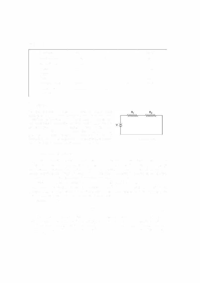
An electric circuit is a closed path consisting of active and |
|
|
||||
passive elements all interconnected and the current flow |
|
|
||||
is confined to the closed path. Fig. i.l shows a typical cir |
|
|
||||
cuit consisting ofone active and two passive elements. An |
|
|
||||
active element is one which supplies energy to the circuit |
|
|
||||
where as a passive element is one which receives energy |
|
|
||||
and then this energy is converted into heat (resistor) or |
|
|
||||
stores it in an electric (capacitor) or magnetic field (induc |
Fig. i.1 |
Electric circuit. |
||||
tor). The battery is the active element in Fig. i.l. |
|
|
|
|||
i.3 ELECTRIC CURRENT
The concept of charge is based on atomic theory. An atom has positive charges (protons) in its nucleus and an equal number of electrons (negative charges) surround the nucleus making the atom neutral. Removal of an electron leaves the atom positive charged and addition of an elec tron makes the atom negatively charged. The basic unit ofcharge is the charge on an electron. The mks unit of charge is coulomb. An electron has a charge of 1.062 x l0-19 C.
When a charge is transferred from one point in the circuit to another point is constitutes what is known as electric current. An electric current is defined as the time rate of flow of charge through a certain section. Its unit is ampere. A current is said to be ofone ampere when a charge of 1 coulomb flows through a section per second.
Mathematically,
i. = |
dq |
(i.l) |
|
- |
|
|
dt |
|
If charge q is expressed in coulomb and time in second, 1 amp flow of current through a section is equivalent to approx. flow of 6.24 x 10¹⁸ electrons per second through the section.
Yet another method of defining electric current (1 amp) is as the constant electric current in two infinite parallel conductors separated from each other by 1 m, experience a force of 2 x 10⁻⁹ Nim.