Basic_Electrical_Engineering_4th_edition
.pdf4 ELECTRICAL ENGINEERING
i.4 ELECTRIC POTENTIAL
Law ofconservationofenergy states that energy can neither be created nor destroyed. However, its form can be converted i.e., energy can be converted from one form of energy to another e.g.
Electromechanical energy conversion, Electro-chemical energy conversion, MHD energy
conversion, photoelectric energy conversion etc. In all these cases the function of each of these |
|
sources of electric energy is the same in terms ofenergy and charge |
the energy is spent as |
i.e.,
work for transporting charge from one point to another in a circuit. The movement of charges contribute to current and the amount of work done per unit charge is the potential difference between the two points. The electronic charges flowfrom a lower potential to a higher potential and these contribute to electronic current, whereas the conventional current is considered to flow from higher potential to lower potential.
If a differential charge dq is given a differential energy dw, the rise in potential of the
charge |
v = |
|
|
|
dw |
(i.2) |
|
|
|
dq |
|
The units of potential or potential difference as derived from equation are joule/coulomb |
|||
Watt sec |
Watt |
. |
|
or Amp. sec |
|
is termed as volts. |
|
or Amp. and usually - |
|
||
We have defined electric potential in terms ofelectronic charge flow. However we can also explain with reference to static charges, considering electric field due to such charge. Suppose we have a point charge Q in space located at some point. The very presence ofthis charge gives rise to an electric field emanating radially from this charge in all directions, as shown in Fig. i.2. The strength of the electric field decreases as we move away from the charge Q which practi cally reduces to zero at infinity. Ifwe move a differential charge dq from = towards the charge Q, the differential charge experiences a force ofrepulsion or attraction depending upon whether the two charges Q and dq are of same polarity or opposite polarity respectively. Suppose Q and dq are positively charged. If we bring charge from infinity to point r1 from Q, the force experi enced by the charge dq according to Coulomb's law is given as
dF= Q. dq |
|
|
|
4 £ |
r12 |
|
|
7t |
o |
IIr1 |
1-:tJ |
//'/,,//';Q/'---------------,'',/ |
4IIr------------2 |
||
,./ |
|
|
|
Electric field
Fig. i.2 Defining potential with respect to electric field (static charges).
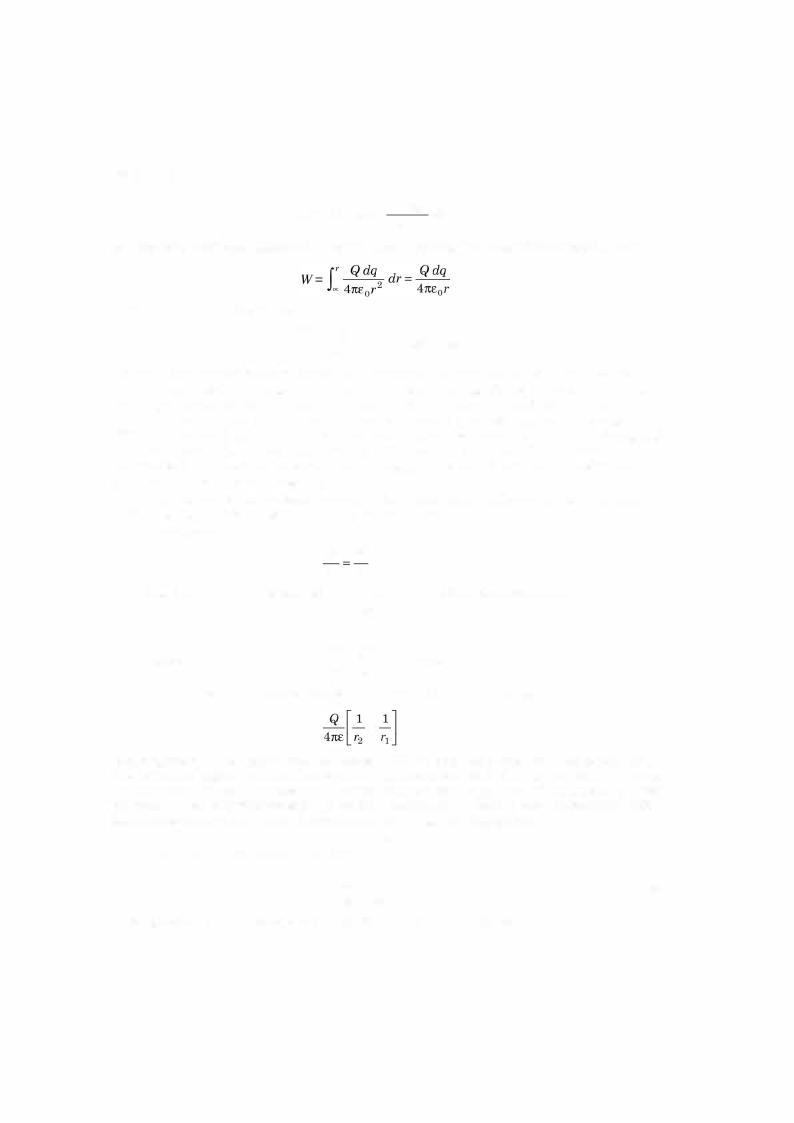
or in general ifthe distance is r from the charge Q the force experienced by the charge dq is
dFf - Q dq2 a-r 4n£0r
where ar is a unit vector along the line joining Q and dq and indicates the direction of force.
Nowifthis differential charge is moved through a distances dr, the workdone on dq against the electric field is
6 |
ELECTRICAL ENGINEERING |
Thus, |
power p = v x i |
Since |
dw |
p = dt . |
Example i.1. A person receives a severe shock when he is subjected to a current of25 mA
for a time duration of 30 ms. How many electrons pass through the person. |
|||
|
Q = |
t = 25 x 10-8 x 30 x 10-8 = 75 x 10-1> C |
|
Solution. |
|
I |
|
Since |
|
|
1 C = 6.242 x 10¹⁸ electron |
Hence no. of electron |
= 75 x 6.2421 x 1013 |
||
|
|
|
= 4.68 x 10 5 Ans. |
Example i.2. A lightning discharge between clouds during a thunder storm is of 20 C. The time of the discharge is 10 m sec. Determine the average lightning current.
|
q |
20 |
= 2 kA Ans. |
Solution. |
I = - = |
10 x 10-3 |
Example i.3. A device stores 500 J of energy and releases this energy in the form of an electric current of 40 A which has a duration of 15 m sec. Determine the average voltage across the terminals of the device.
Solution. Since |
Energy W = Vlt |
|
||
|
500 = vx 40 x 15 x 10-3 |
|||
or |
V= |
500 |
3 = 833 volts Ans. |
|
40 x 15 x 10 |
||||
|
|
- |
||
|
|
|
||
i.5 RESISTANCE
We know that a random motion of free electrons results from the exchange of the outer orbit between the atoms. In order to establish a net or average flow of electrons in one direction an external force is necessary. This force is necessary to overcome a resistance. Ifthe material is a good conductor ofelectric charges, relatively smaller force is required to produce a current flow. Copper and silver are good conductors. Silver is better conductor than copper.
A good insulator is one which effectively eliminates the flow of current of any practical magnitude. Polystyrene is a good insulator2 and2 has approximately 3 x 10¹⁸ free electrons per cubic metre. Materials which have 10 1 to 10 5 free electrons per cubic metre are known as semiconductors.
From Table i.1 it is found that the derived units forresistance is ohm, its quantity symbol is R and the unit symbol is Q. The unit for electric resistance is defined as
|
Ifthe potential difference between point a and b is say 1 V when the current in the circuit |
|
|
1 A, the resistance between points a and b is said to he of 1 Q. |
|
|
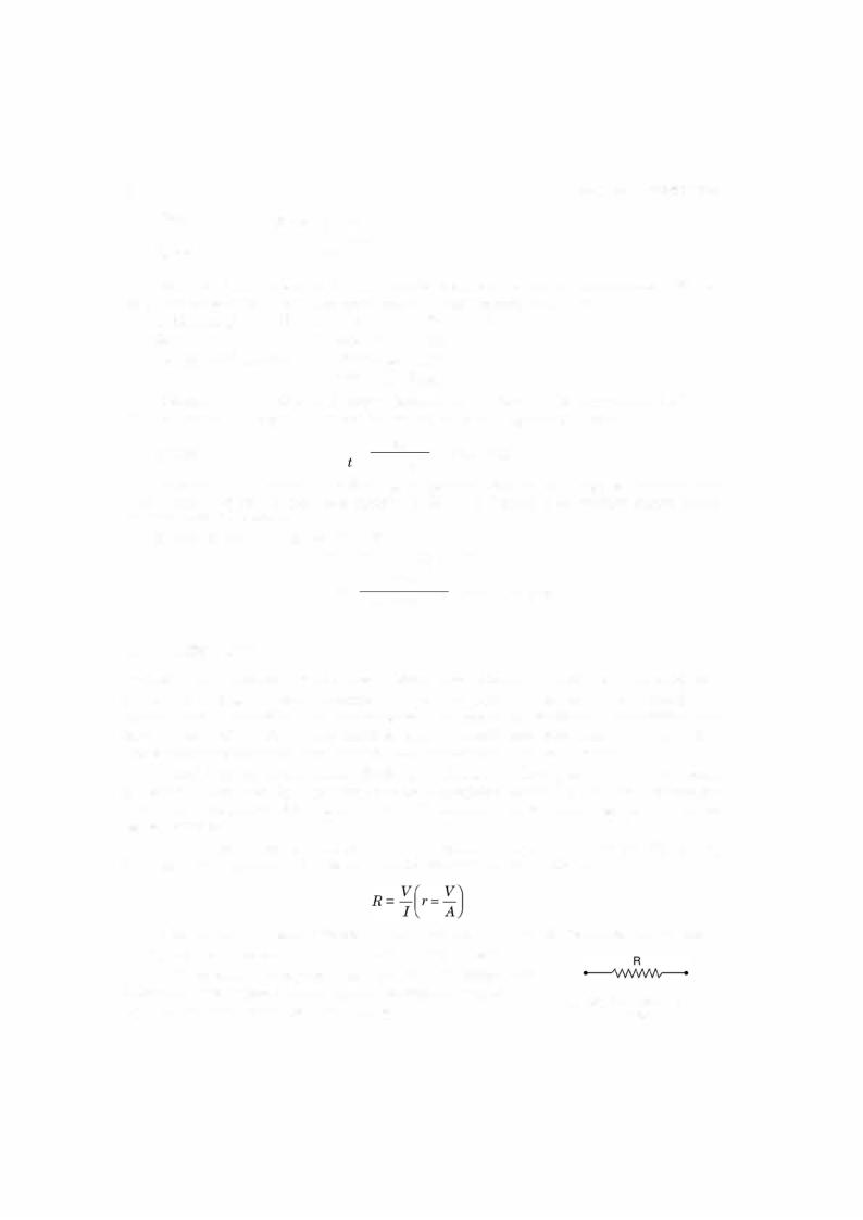
A circuit element designed to have property ofresistances is |
|
known as a resistor andits circuit symbol is shown in Fig. i.3. The |
Fig. i.3 Circuit symbol of a |
|
is |
|
|
resistors normally are in the form of wires. |
resistor. |
|


8 ELECTRICAL ENGINEERING
|
1 |
1 l |
l |
|
Now |
- = - - = - |
Q |
||
R = G |
y A |
yA |
||
or |
G = yAl |
s |
|
|
It is to be noted that resistance of a conductor increases with increase in temperature. If R1 is the resistance of a conductor at T1 and Ra at Ta and coefficient ofresistance at Ta is say aa, then these quantities are related as
R1 = R0 + a0 (T1 - T0)R0 = R0 [l + a0(T1 - T0)]
Whenever an incandescent bulb is switch in to electric supply, its cold resistance being smaller, it draws large current at the beginning and with time as the filament gets heated its temperature increases gradually and then the current decreases gradually and finally a par ticular temperature of the filament is reached when there is no further increase in resistance, the current also attains afixedvalue. Theresistancetemperaturecoefficient for copperis 0.00426 ohm/°C/ohm at 0°C.
i.6 POWER
If potential is multiplied by current ,we have
V x I = dWdq x dqdt = dWdt = p
which gives rate of change of energy with time and is equal to power. The SI derived unit for power (P) is watt expressed as Joule per sec.
i.7 ENERGY
From the previous section we have
|
dW |
|
P = - |
or |
dt |
dW = Pdt = VI dt |
|
or |
W = |
|
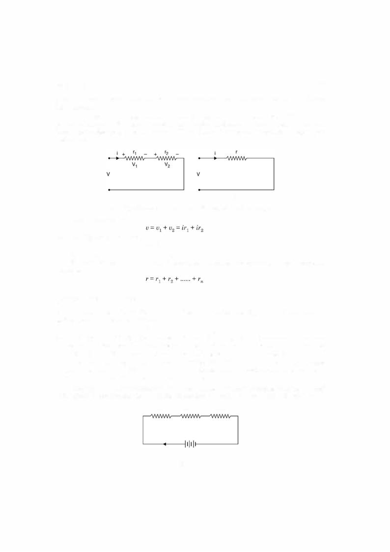
f VI dt |
and energy of a device is defined as the capacity of doing the work and its derived unit is watts-sec.
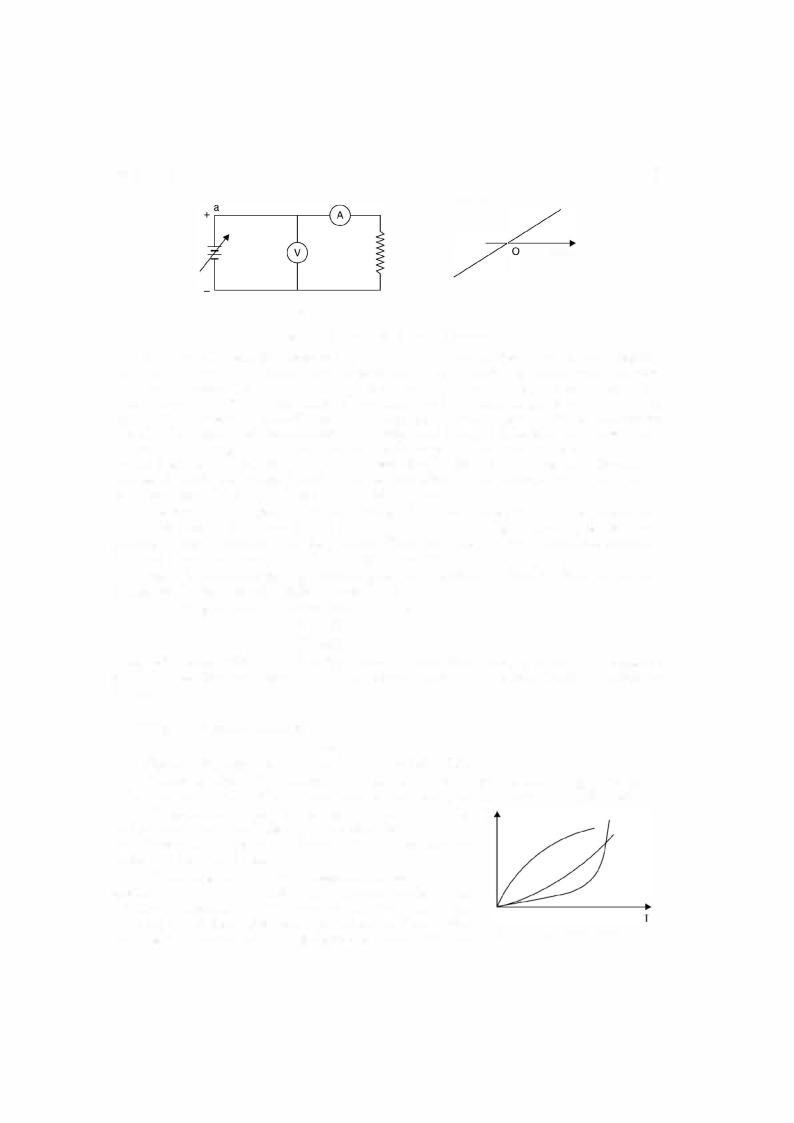
i.8 OHM'S LAW
Simon Ohm a german physicist investigated the relation between current and voltage in a resistor and published his experimental results in 1827. The experimental set up is shown in Fig. i.4.
DC CIRCUITS |
|
|
Current j |
9 |
b |
(a) |
R |
Voltage |
|
|
|
|
(b) |
Fig. i.4 (a) Experimental set-up (b) results.
A d.c. variable supply voltage is connected with positive terminal at point a and negative terminal at ' b' as shown. Asvoltage is increased, the current recorded bythe ammeterincreases. For every voltage value the current is recorded and the corresponding point is plotted on the rectangular graph. With this a straight line graph passing through origin is obtained in first quadrant. Next the terminals ofthe variable de supply are interchanged i.e. a is connected to -ve polarity ofde supply and b is connected to +ve polarity of de suply. Since both the voltmeter and ammeter are moving coil, their individual connection should also be interchanged so that meters can read up scale. This has been done to reverse the direction of flow of current through the resister R. Again the voltage is varied and corresponding to each voltage, current is recorded and the pairs of V and I are plotted in the third quadrant.
The experimental results indicate that there is a linear relationship between the current and voltage both in the first and third quadrant. The slope of straight line is also same in both the quadrants which shows that the potential difference across the terminals of the conductor is proportional to the current passing through it i.e. V = I.
|
Also it is found that for a constant current in the conductor resistance should be changed |
||
proportional to the potential difference i.e. Voc R. |
|||
|
Combining the two proportionalities, we have |
||
|
|
V |
IR |
or |
|
V |
= kIR |
where k is a constant of proportionality. However, the units of voltage, current and resistance |
|||
are defined so that the value of |
k =oc1. When the current is 1 amp, voltage 1 volt, the resistance |
||
is |
1 Q. |
||
|
|
l = k . 1 . 1 |
|
Thus the equation becomes
V= IR
The equation explains ohm's law which is stated as follows :
Physical condition (Temperature, Pressure etc.) of the conductor remaining constant, the
voltage across the terminals of a conductor is proportional to the current flowing through it. |
||
The resistances which Ohm considered are linear i.e. the v |
|
|
resistances which have linear V-I characteristic. Also, these |
|
|
are bilateral i.e. irrespective ofdirection offlow of current the |
|
|
resistance does not charge. |
|
|
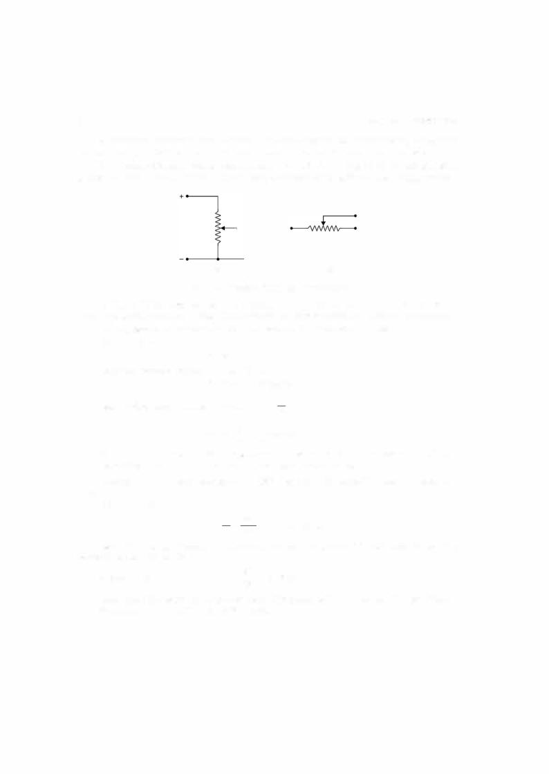
There are some non-linear resistance derives also e.g. in |
|
|
electronic, a diode or a triode and many such devices have |
|
|
minimum resistance when these are forward biased and when |
|
|
reversed biased these offer very high resistance. Some of the |
Fig. i.5 Non linear resistances. |
|
non-linear resistance V-I characteristics are shown in Fig. i.5. |
||
|
||
10 |
ELECTRICAL ENGINEERING |
A resistance is always rated in terms of its ohm's value and current rating or wattage rating. Usually resistances used in electronic circuitry use wattage and ohmic ratings.
Two basic applications ofa resistance are shown in Fig. i.6. In Fig. i.6 (a) it is being used as a potential divider in d.c. circuit. Here we want de voltage variable from a fixed supply voltage.
(a)(b)
Fig. i.6 (a) Potential divider (b) Current limiter.
In Fig. i.6 (b) it is used as a currentlimiting device and is inserted in series with the circuit where the current is to be limited. When used for current limitation, it is known as rheostat.
The expression for power dissipated in a resistor R is derived as follows :
We know that
P = VJ
Using one version of ohms law i.e. V = IR
P = (JR) I = FR watts Again using second version of ohms law I = Rv
v v2
P = V . - = - watts.
R R
It is to be noted that Vis the voltage across the resistance R and not the supply voltage. Depending upon the situation one of these formulae can be used.
Example i.5. The load resistance in a 220 V circuit is 80 ohms. Determine the load cur-
rent.
Solution. Using ohm's law
v = 220
I = R BO = 2.75 A Ans.
Example i.6. Determine the conductance ofa short circuit on 120 volt which results in a short circuit current of 500 A.
Solution. Since
Example i.7. Determine the power rating of a device which is rated at 15 A 250 Volts. Solution. P = VI= 250 x 15 = 3750 watts.

DC CIRCUITS |
1 1 |
Example i.8. A resistor is rated for 1 0 kQ. 1 watt. Determine its maximum voltage and
current ratings. |
v2 |
v2 |
|
||
Solution. |
P = R = l |
= 10,000 |
or |
V2 = 10,000 |
|
or |
V= 100 volts Ans. |
|
Similarly to calculate maximum current rating |
||
|
P = FR = 1 = F . 10,000 |
|
or |
1 |
|
I = - = 0.01 A or 10 mA. |
||
|
100 |
|
Example i.9. An electric motor operatingfrom 220 volts supply takes a current of8A. The motor has an efficiency of 80%. Determine the output of the motor.
P = VI = 220 x 8 = 1760 watts.
Since the efficiency of the motor is 80%, 80% ofinput will be the output i.e.
Power output = Power input x efficiency
= 1760 x 0.8 = 1408 watts Ans.
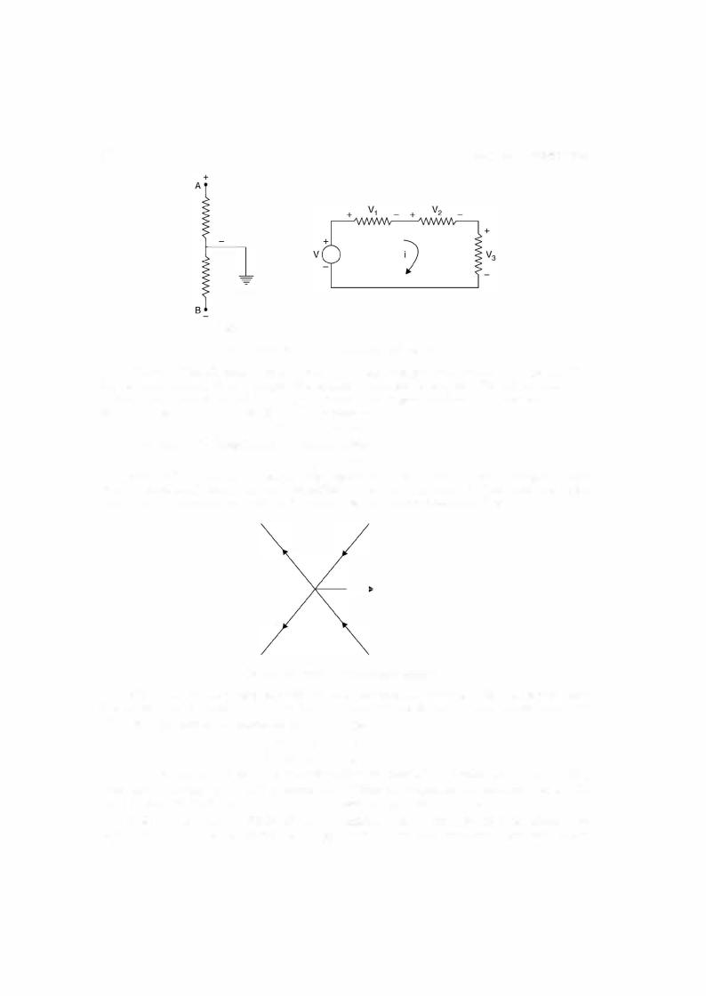
i.9 KIRCHHOFF'S LAWS
Kirchhoffs postulated two basic laws way back in 1845 which are used for writing network equations. These laws concern the algebraic sum ofvoltages around a loop and currents enter ing or leaving a node. The word algebraic is used to indicate that summation is carried out taking into account the polarities of voltages and direction of currents. While traversing a loop we will take voltage drops as positive and voltage rises as negative. Also while considering currents at a node, the currents entering the node will be taken as positive and those leaving would be taken as negative.
Kirchhoffs voltage law usually abbreviated as KVL is stated as follows :
The algebraic sum ofall branch voltages around any closed loop ofa network is zero at all instants of time. Alternatively, Kirchhoffs voltage law can be stated in terms of voltage drops and rises as follows. The sum of voltage rises and drops in a closed loop at any instant of time are equal. KVL is a consequence of law of conservation of energy as voltage is energy or work per unit charge. If we start from one node in a loop and move along the closed loop and come back to the same node, obviously the total potential difference or sum of potential rises must equal the total sum of potential falls. Just as, if we start from one point on the surface of the earth and after travelling through valleys and hills come back to the same point, the total displacement is zero. We talk elevation's and depression on the earth with respect to the sea level. Similarly, in case ofvoltages we take ground as the referencewhichis shown in Fig. i.7(a). Here potential of node A is above the ground and that ofB is below the ground potential.