Basic_Electrical_Engineering_4th_edition
.pdf
DC CIRCUITS |
15 |
Power loss = (947.5220 )2
So, R = 927.5 Q is more appropriate.
Series resistance as mentioned earlier is used to limit the current in the circuit. Suppose we have an appliance rated for 1 10 volts. However, the source voltage available is 220 volts. The device can't be connected directly to the supply. Hence a resistance in series with the device is connected and then the combination put across the supply and by adjusting the series resistance 110 volts can be adjusted across the device.
Example i.12. Determine the resistor required to reduce the line voltage from 120 V to 80
uolts for the operation of a deuice. The deuice is rated at 120 V, 100 watts.
Solution. The resistance of the device is
v2 |
|
|
100 |
|
1202 |
|
|
|
|
|
|
|
|||
Rd |
|
|
120 |
|
Rd |
|
|
|
|
|
|
|
|||
or |
R |
d |
= |
2 |
= 144 |
Q |
|
|
|
|
|
||||
|
|
|
|
100 |
|
|
8° = |
|
|
|
|||||
device at reduced voltage is |
|
|
A |
||||||||||||
The current in the- = |
|
= - - |
|
|
144 |
|
0.555 |
|
|||||||
The total resistance required to circulate 0.555 |
A current at full voltage of 120 V is |
||||||||||||||
|
RT |
|
120 |
|
216 |
3 |
|
|
|
|
|
||||
|
|
0.555 |
|
Q |
|
= |
72 Q |
Ans. |
|||||||
Therefore, external |
resistance required is 216 - 144 |
||||||||||||||
|
|
|
= - -. = |
|
|
|
|
|
|
||||||
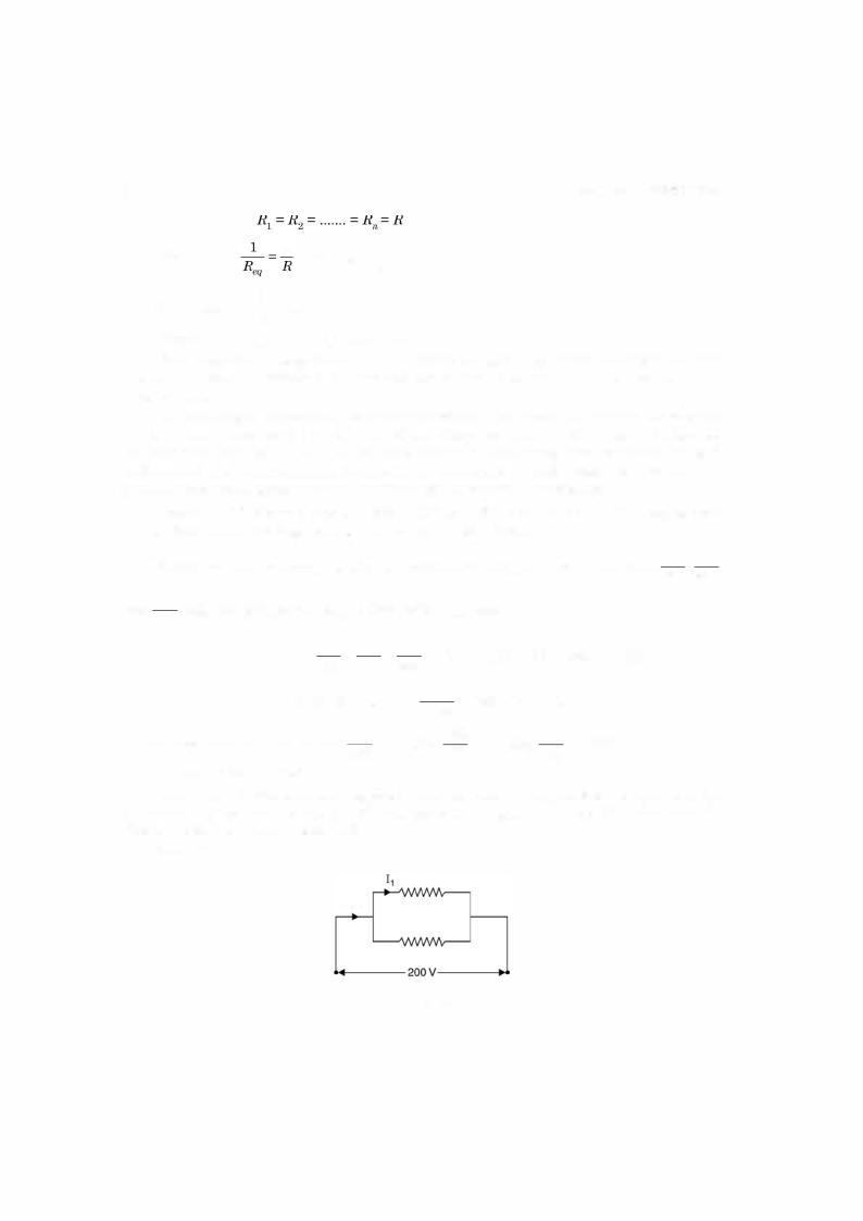
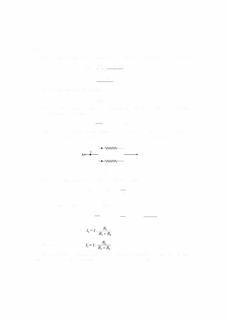
i.1 0.1 Parallel Circuits
In a parallel circuit two or more than two resistors are connected to the same source voltage V
i.e. the voltage across each resistance is equal to supply voltage. Ifthese are n resistances R1 |
, R2, |
|||||
. . . . . . Rn connected in parallel with the supply, the current through various resistances will be |
||||||
|
I1 R1v , I2 |
R2v |
, |
· · · · · · · |
In= Rvn |
|
|
- |
- |
|
|
|
|
|
current in the line or through the source will be sum of these currents |
|
||||
and hence the total |
I ==I1 + Iz +=...... + In |
- |
i.e. |
|||
or
Let
Hence
I
-v
v
-I
-1 -
Req
=
=
= =
v
R1
1 - R1
Req
-1
R1
+
+
+
v
Rz
1 -
-1
R2
++ |
........ + Rv |
|
1 |
n |
|
|
||
........ + - |
||
|
Rn |
|
+ |
....... + -1 |
|
|
Rn |
|
20 |
|
|
|
|
|
|
|
|
|
|
|
|
|
|
ELECTRICAL ENGINEERING |
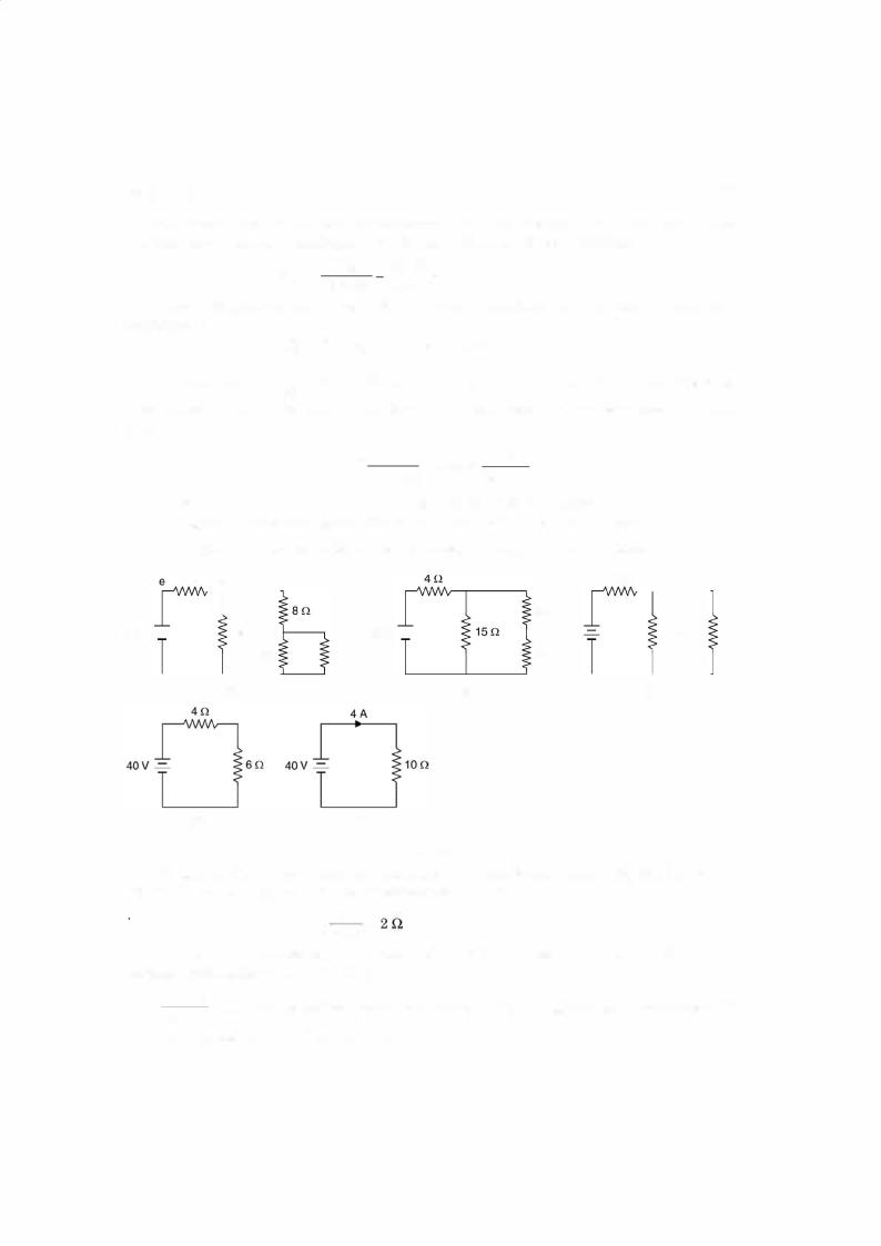
Therefore, current from the battery is 4010 = 4 A and same current flows through 6 Q of |
|||||||||||||||
Fig. i.17 (a). Now in Fig. i.17 (c) current through 1 |
|
Q is |
4 x 10 |
= |
1.6 Q and hence current |
||||||||||
through 10 Q resistance is 4 - 1.6 2.4 A |
|
|
|
5 |
|
25 |
|
||||||||
So, in Fig. i.17 current through 8 Q and 2 Q is 2.4 A |
|
|
|
||||||||||||
In Fig. i.16 (a) current |
through |
6 |
Q is |
|
|
|
|
|
|
|
|
||||
|
|
= |
|
|
|
|
|
|
|
|
|
||||
|
|
3 |
3 |
= |
2.4 x |
1 |
= |
0.8 A |
|
|
|
|
|
||
|
|
3 6 |
= |
|
|
|
|
|
|||||||
|
2.4 x |
|
S |
|
|
|
|
|
|
||||||
and hence current through |
|
|
Q is 2.4 - 0.8 |
|
1.6 Amp. Ans. |
|
|
|
|||||||
Let us consider a few |
applications of KVL for solving electric circuits. |
|
|||||||||||||
|
|
|
+ |
|
|
|
|
|
|
|
|
|
|
|
|
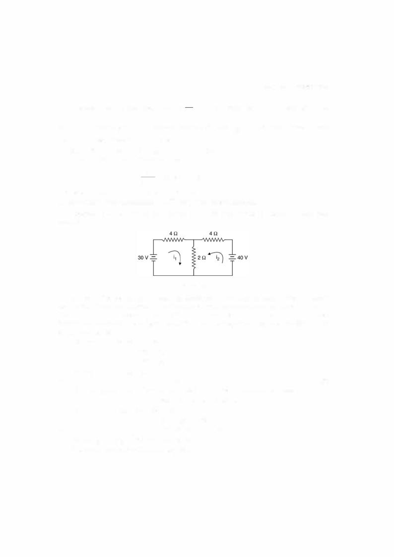
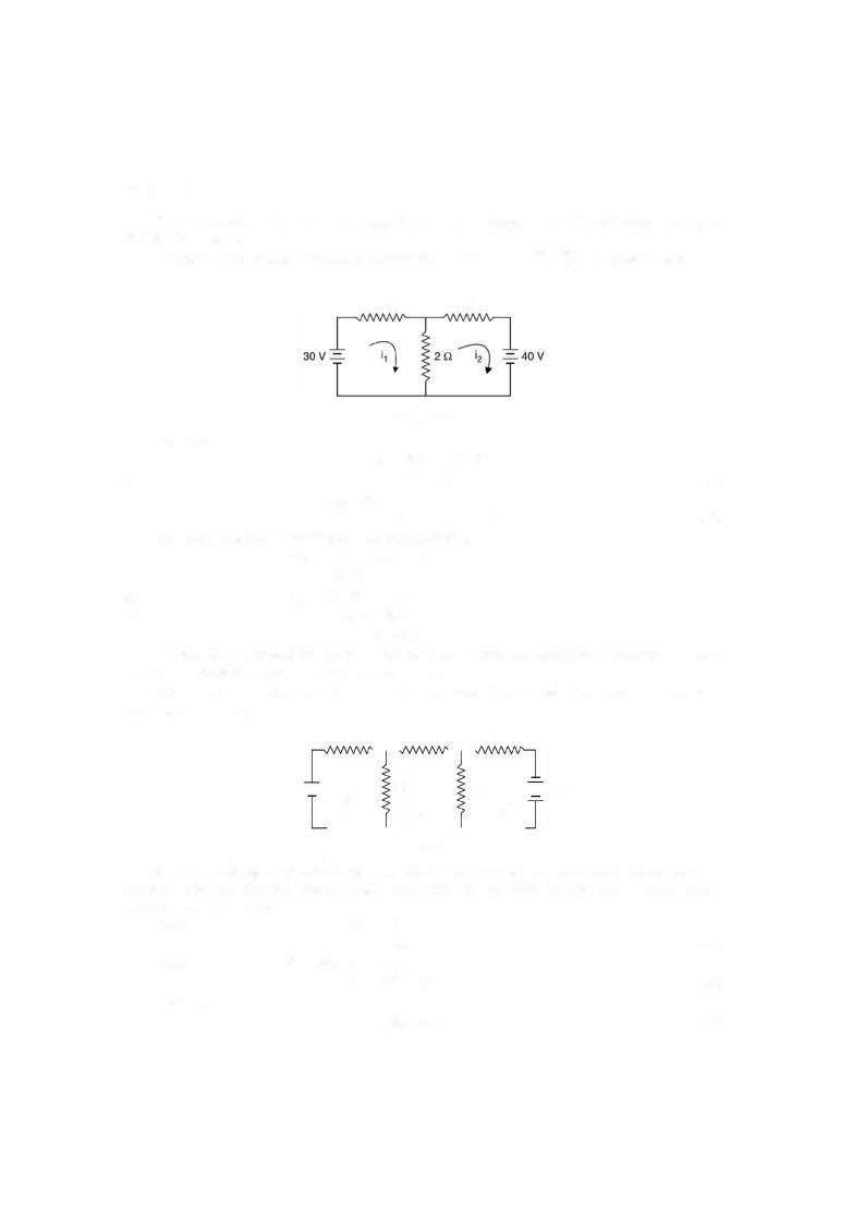
Example i.18. Determine the current in all the branches of the network using loop analysis.
Fig. Ei.1 8
Solution. Let the currents i1 and i2 be flowing in the two loops as shown. It is to be noted that the direction of the currents is arbitrary. However, depending upon the values of i1 and i2 thus obtained we can ascertain the direction. If they are coming out to be positive, the direc tions remain as shown in the figure, otherwise one with negative value, the direction of this
current is reversed. |
|
|
|
Writing loop equation for loop 1 |
|
|
|
|
4i1 + 2(i1 + i2) |
30 |
|
or |
6il + 2i2 |
= 30 |
...(1) |
Loop 2 |
4i2 + 2(i1 + i2) |
= 40 |
|
or |
2il + 6i2 |
= 40 |
...(2) |
Multiplying equation (2) by 3 and subtracting equation (1) from this we have
|
|
|
|
|
|
16i2 = 90 |
or |
i2 = 5.625 A |
|||
Hence |
|
|
|
2i1 + 6 x 5.625 = 40 |
|
|
|
|
|||
or |
|
|
|
|
|
2il 40 - 33.75 |
|||||
|
= |
|
|
= |
2i |
= |
6.25, i |
|
3.125 A Ans. |
||
Hence |
i3 |
i1 |
+ i2 |
5.625 + 3. 1251 |
8.75 A1 |
|
|
||||
|
|
= |
= |
|
|||||||
The current through 2 Q branch is |
=8.75 |
A |
|
||||||||
DC CIRCUITS |
21 |
Since both the currents i1 and i2 are found to be positive hence the directions shown in Fig. Ei.18 is correct.
Suppose we take the direction ofcurrent for i2 as shown in Fig. Ei.18.1 shown here
4 !l |
4 ! l |
|
|
|
|
|
Fig. Ei.18.1 |
|
|
|
||
For loop 1 |
|
|
|
|
4il + 2(il - i2) |
|
30 |
|
||
or |
|
|
|
|
|
|
||||
|
|
|
|
6 |
- 2i |
|
= 30 |
...(1) |
||
|
|
4i2 + 2(i2 - i1)i+1 40 =2 |
= |
|
|
|||||
or |
|
|
|
|
- 2i1 + 6i2 |
|
- 40 |
...(2) |
||
Multiply equation (2) by 3 and add to equation |
(1) |
|
|
|||||||
= |
O |
|
|
|||||||
|
16i2 = - 120 + 30 = - |
90 |
|
|
|
|||||
|
i2 = - 5.625 |
|
|
|
|
|
|
|||
and |
- 2i1 - 33.75 = - 40 |
|
|
|
|
|
||||
or |
|
- 2i1 = - 6.25 |
|
|
|
|
|
|||
or |
|
i1 |
|
3.125 A |
|
|
|
|
||
We find the i2 |
is coming out to be negative and hence the direction of current in loop 2 |
|||||||||
should be opposite to what is shown |
in Fig. Ei.18.1. |
|
|
|
|
|||||
|
= |
|
|
|
|
|
|
|||
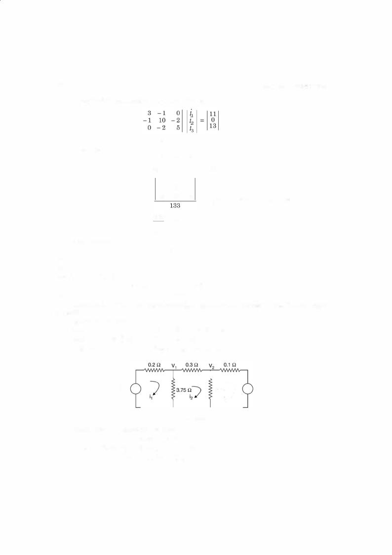
Example i.19. Determine the current in each branch of the networh shown in Fig. Ei.19 |
||||||||||
using loop analysis. |
|
|
|
|
|
|
|
|
|
|
|
|
2 n |
|
|
7 Q |
|
|
3 Q |
||
|
1 1 v - = - |
i17 1 n |
i27 2 n |
i37 -=- 1 3 v |
||||||
Fig. Ei.1 9
Solution. Since there are three loops, three independent loop equations are required to solve the network. Suppose the directions ofcurrents are as shown in Fig. Ei.19. Writing equa tions for the three loops
Loop I |
|
|
2i1 |
+ l(i |
1 |
- i2) = 11 |
||
Loop II |
7 |
+ 2(i |
|
|
3il - i2 |
11 |
||
- ) + (i |
- i )1 |
= 0 |
||||||
|
i2 |
|
|
|
|
|||
or |
2 |
- ili3+ l0i22 - 21i3 |
= 0 |
|||||
Loop III |
|
|
3i |
|
+ 2(i |
|
- i ) = 13 |
|
|
|
|
|
|
- 2i23 |
|||
|
|
|
|
3 |
+ 5i2 3 |
== 13 |
||
...(1)
...(2)
...(3)