Basic_Electrical_Engineering_4th_edition
.pdf34 |
ELECTRICAL ENGINEERING |
Since B and l are constant and not function of time |
|
e = - Blv |
(ii.11) |
where v is the velocity with which the conductor is moving at right angle to the flux density B.
In Fig. ii.3 (b), the conductor moves at angle 8 with respect to magnetic field. Therefore, if the conductor moves a distance dx in time dt, the component ofdistance moved at right angle to
the field is dx sin |
|
and hence the flux cut by the conductor |
|
||
However in |
Fig. ii.2 (c) |
= B . l dx sin 8 and hence e = - Blv sin 8 |
...(ii.12) |
||
|
8 |
|
since the conductor is movingparallel to the flux density hence |
||
and the voltage induced in the coil is zero, Equation (ii.12) is a general equation for evaluating emf induced in coil moving in a static magnetic field. Equation (ii.12) can be written in vector notation as
e = - l (v x B) volts |
(ii.13) |
Next we take up statically induced emf.
ii.5. 1 Statically Induced emf or Transformer emf
Here we consider the circuit or conductor or coil to remain stationary but the magnetic field is time varying. The statically induced emf may be (i) mutually induced or (ii) self induced.
In the first-case we have two windings placed close to each other and a time varying voltage source is connected to one winding which induces voltage in the other winding. In the second case we have single winding and when a time varying voltage source is connected across its terminals, time varying current through the winding gives rise to time varying magnetic field which links the winding itself and emfis inducedin the winding and hence this emfinduced is known as self induced.
Suppose we have a flux density normal to a differential area ds and the coil in the field is single turn, then flux linkage \jf can be given as
The surface over which the integration is to be carried out is the surface bounded by the periphery of the coil. The induced e.m.f. is therefore, given as
e = d\jf |
= |
d |
B . ds |
(ii.14) |
and for a time varying magnetic fielddt |
|
dt ff |
-- |
|
e = - f - |
. ds |
(ii.15) |
||
Ifwe consider the flux density to be harmonically varying and let the area through which the flux flows is constant then let <I> = <l>m sin wt and let N be the no. ofturns ofthe coil, the flux linking will be
Hence |
\jfe = - dt = - N qim w cos wt |
|
= <j>N = N<j>m sin wt |
|
dcp |
|
= N <l>m w sin (mt - rt/2) |


36 |
ELECTRICAL ENGINEERING |
Ifwe have to find outinductance ofa given coil when the saturation ofthe core takes place we make use of equation (ii.17) and we define inductance as the ratio of differential change in flux linkages to differential change in current.
To obtain physical dimensions ofthe coil we make use of equation (ii.18)
Since |
< j > = MMF = - |
|
||
|
|
|
Ni |
|
|
Reluctance |
l!µA |
|
|
Substituting for <!> in equation (ii.18) we have |
|
|||
|
L = N{Nil(llµA)} |
= |
N2µA |
(ii.19) |
|
i |
l |
|
|
i.e. the inductance of a coil is directly proportional to (i) Square of number of turns (ii) directly proportional to the permeability of the core material and area of cross-section of the core and inversely proportional to the length of the magnetic circuit. Usually it is the no. of turns are varied to obtain a desired value of inductance. It is to be noted that for small values of induc tances in term of mH or µH, usually air cored coils are used as µr = 1 for air and µr is quite high for magnetic materials.
ii.7 MUTUAL INDUCTANCE
In Fig. ii.6 current 11 produces a total flux <j>11in coil 1. The subscript 11 means one-one and not eleven i.e. the flux of coil 1 that links coil 1. The resulting self inductance L1 of coil 1 is
Common |
|
flux path |
q,22 |
<!>11 |
Coil 2 |
Coil 1 |
Fig. ii.6 Mutual flux and mutual inductance.
(ii.20)
Similarly current 12 produces a total flux <j>22 in coil 2 and, therefore, the self-inductance of coil 2 is
L |
2 |
= N2<!>22 H |
(ii.21) |
|
12 |
|
|
The directions of <!>n and <j>22 have been shown as per the direction of current flows in the |
|||
respective coils. A part of flux <!>n |
links coil 2. Hence total flux in coil 2 consists of two compo |
||
nents, its own flux <j>22 plus the part of <!>n whichis common1 . The amount offlux ofcoil 1 which links coil 2 is <ji12. The subscript "12" means from coil to coil 2. Similarly a part offlux <j>22 ofcoil 2 which links coil 1 is <!>21.

ELECTROMAGNETIC INDUCTION |
41 |
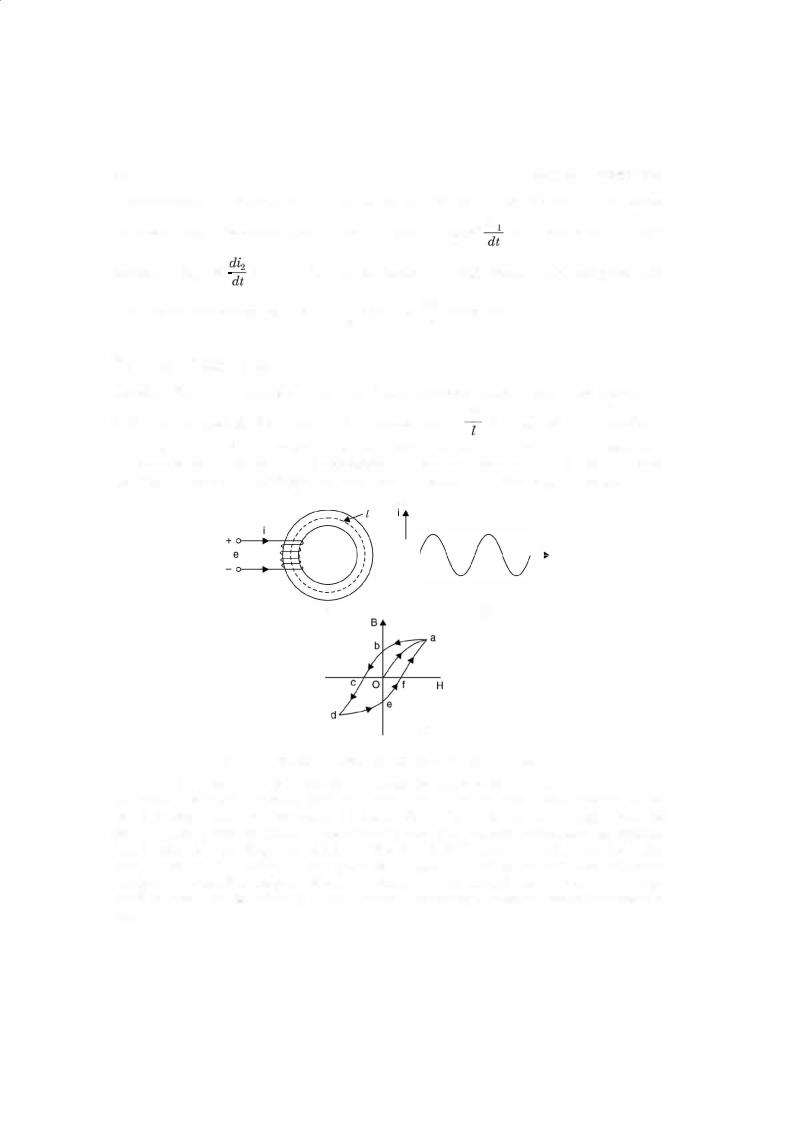
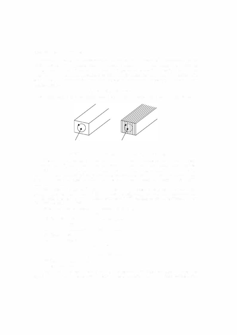
0.5 to 5 mm in electrical machines and from 0.01 to 0.5 mmin devices used in electronic circuits which operate at frequencies. Each lamination is insulated from the others by a coating of oxides or varnish or both so that it offers a high resistance to the flow of eddy currents. The eddy current loss can also be reduced by using a high resistivity core material. Addition of a smallpercent ofsilicon say 3% to iron willincrease the resistivity significantly. The eddycurrent loss in given by
Pe = KefB2m t2 x volume
where t is the thickness oflaminations andKe is a constant which depends uponthe core material.
B B
(a)(b)
Fig. ii.10 Eddy current loss in core (a) Solid core (b) Laminated core.
The sum ofthe hysteresis and eddy current loss is known as core loss or iron loss. Since for a machine f and Em are constant, the core loss is also known as constant loss ofthe machine.
Eddy currents can be used to advantage to electric braking purpose e.g. in moving iron and moving coil measuring instruments eddy currents are utilised to damp out the final set tling of the instrument pointer. Also there are some specially designed machines which utilise eddy current braking.
Example ii.1: A wire oflength 50 ems moves at right angles to its length at 50 mlsec in a uniform magnetic field ofdensity 1 Wb!m2. Determine the e.m.f induced in the conductor when the direction of motion is (i) perpendicular to the field (ii) inclined at 30° to the direction of the field (iii) parallel to the field.
Solution. Voltage induced in a conductor is given by
|
e = Blv sin 8 |
(i) Here B = 1 Wb/m2, l = 0.5 m, v = 50 m/sec. |
|
and |
8 = 90° |
Hence |
e = 1 x 0.5 x 50 x 1 = 25 volts Ans. |
(ii)Here 8 = 30° Hence e = Blv sin 8
=1 x 0.5 x 0.5 sin 30°
=25 x "21 = 12.5 volts Ans.
(iii)Here 8 = 0 since sin 0° = 0
Hence |
e = 0 Ans. |
Example ii.2: A square coil of 20 ems side and with 200 turns is rotated at a uniform speed of 1000 rpm about an axis at right angles to a uniform magnetic field having a flux