Basic_Electrical_Engineering_4th_edition
.pdf

1 1 6 1.4.
1.5. 1.6.
1. 7. 1.8.
1.9. 1.10. 1.11.
1.12.
1.13.
1.14.
1.15.
1.16.
1.17.
1.18.
1.19.
1.20.
|
|
|
|
|
|
|
|
|
|
ELECTRICAL ENGINEERING |
A resistor and a capacitor in series are connected to a 120 V, 60 |
|
|
supply. The impedance ofthe |
|||||||
|
|
|
|
|
|
Determine the value of R and |
||||
circuit is 86 ohms and the power consumed is also 86 W. |
|
|
Hz |
[Ans. 44.17 Q, 35.9 µF] |
||||||
A 200 ohm resistor is in series with a capacitor across 240 V, 60 Hz. Supply. The power isC.100 W. |
||||||||||
Determine C and |
|
|
|
|
|
|
|
[Ans. 9.67 µF, 0. 707 AJ |
||
The resistance of a coil is 140 |
Q and its inductance 0.85 H. Determine the current, the p.f. and |
|||||||||
the circuit |
impedance when the coil is connected to 120 V, 60 |
|
|
supply. |
||||||
|
KV |
I. |
|
|
|
|
|
|||
A 0.1 H |
|
|
Q |
|
[Ans. 0.344 L-66.4, 0.4, 349L66.4] |
|||||
|
|
at a leading p.f. of 0.8. Determine the equivalent series |
||||||||
A 240 V, 50 |
A generator operates |
|
|
Hz |
|
[Ans. 0.922 - j0.691] |
||||
impedance of the load. |
|
|
|
|
|
|
||||
inductor is in series with a 5 resistor. The series combination is placed across a 120 V, 60 Hz supply. Determine the current in rectangular and polar coordinates.
[Ans. 0.415 - jil.128 A]
Two appliances are operated in parallel from a 120 V supply. One draws 12 A at a lagging p.f. of 0.8 and the other draws 8A at 0.75 p.f. lead. Determine the total current and the power.
[Ans. 15.6 - jl.91 A, 1872 W] Two branches connected in parallel have impedances of 120 +jl80 and 150 - jl30 Q respec tively. Determine the branch currents, the line current and the power delivered to the circuit if
it is connected across 115 V supply. |
[Ans. |
0.53 L-56.3, |
0.58 L40.9, 0.732 A, 84.2 |
W] |
||
|
!1 |
!1 |
|
|||
Two circuits, the impedances ofwhich are given byZ1 = 10 +jl5 Q andZ2 = 6 -j8 |
|
W] |
||||
|
are connected |
|||||
in parallel. If the total current supplied is 15 A, what is the power taken by each branch ? |
|
|||||
|
|
|
[Ans. |
737 W, 1430 |
|
|
Discuss various characteristics of a series RLC resonant circuit. Derive mathematical expres sions in support of your discussion.
Define Q of a coil and Q of a series RLC circuit. Show that the voltage across the inductor or capacitor in a series RLC circuit is Q times the supply voltage at resonance.
What are half-power frequencies in a series RLC resonance circuit? Derive an expression for bandwidth of the circuit.
Discuss various characteristics of a general parallel RLC circuit at resonance. Derive resonance frequency when (a) coil is loss free (b) capacitor is loss free (c) both are loss free. Draw the equivalent circuit when Q of the circuit is high.
Derive an expression for Q of a parallel resonance circuit from first principles. A given parallel circuit has certain bandwidth. Ifit is required to obtain a lower bandwidth what measure should be taken to achieve this?
Explain what you mean by selectivity of a circuit and explain how it can be improved.
A 70 ohm resistor, a 5 mH coil and a 15 pF capacitor are in series across a 110 volt supply. Determine the resonant frequency the Q of the circuit at this frequency, the voltage across the capacitor at resonance. [Ans. 581 kHz, 261, 28.71 kV]
A variable inductor is connected in series with a resistor and a capacitor. The circuit is connected to a 200 volt 50 Hz supply and the maximum current obtainable by varying inductance is 0.314 A. The voltage across the capacitor then is 300 V. Determine the circuit constants.
[Ans. 3.3 µF, 637 Q, 3.04 HJ A coil of 20 Q resistance and 0.2 H inductance is connected in parallel with a capacitor of 100 µF capacitance. Find the frequency of resonance and the effective impedance at resonance.
[Ans. 31.8 Hz, 100 Q]
A-C CIRCUITS |
1 17 |
1.21.A series circuit consists of a 115 Q resistor, a 0.024 tFcapacitor and coil of inductance L. If the resonant frequency of the circuit is 1000 Hz determine L and the bandwidth.
[Ans. 1.055 H, 17.3 Hz]
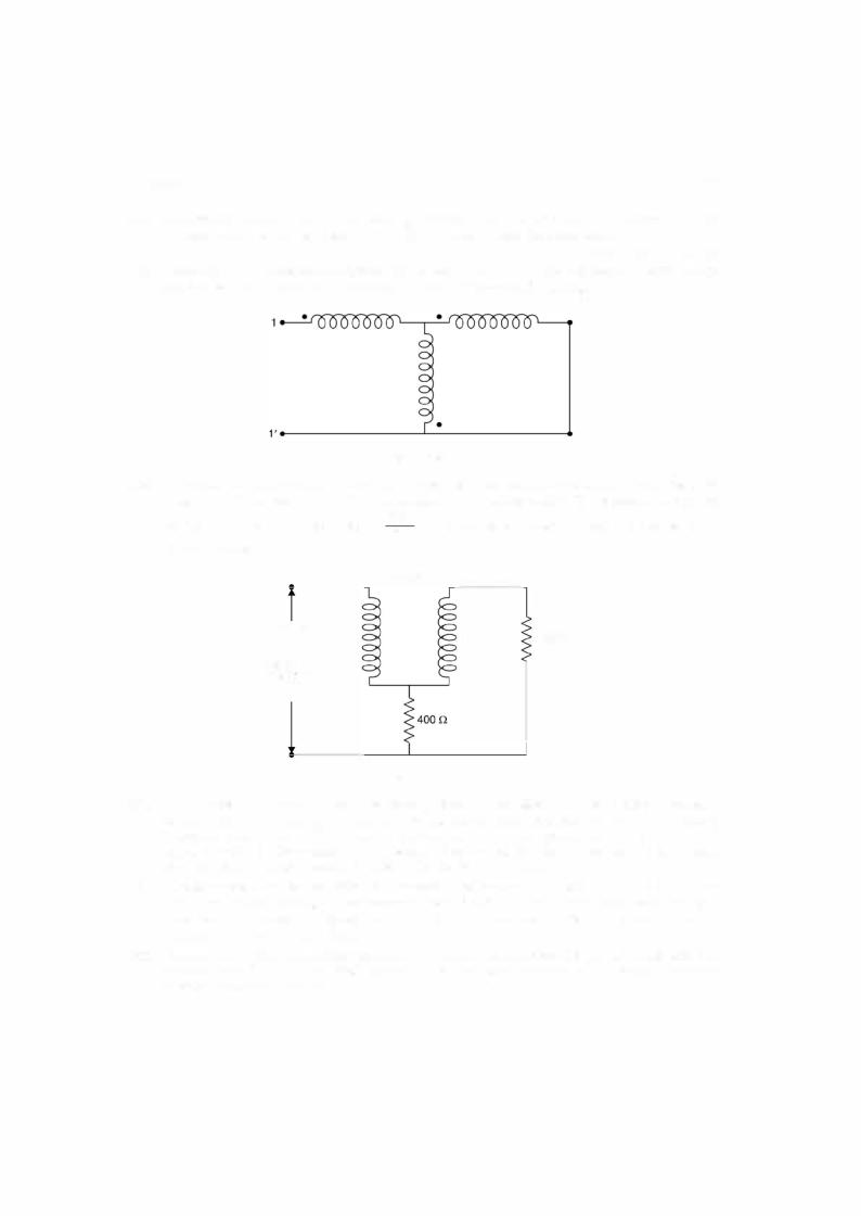
1.22.Three coils are interconnected with winding sense shown by dots. The self inductance ofthe coils are 2 H each and the mutual inductance 1 H each. Determine Leq between 11'.
Fig. P1 .22
1.23.Two coils are wound on the same core and have negligible resistance as shown in the Fig. 1.23. Determine the current in the 1000 ohm resistor and its phase angle with respect to the applied
voltage of 100 volt at a frequency of 50002it Hz when the coils act (i) in the same sense (ii) in opposite sense.
M = 0.05 H
1 00 v |
0.2 H |
|
0.1 H |
1 ooo n |
5000 2rr Hz
Fig. P1 .23
1.24.A cast steel ring has a circular cross sections 3 cm in diameter and a mean circumference of 80 cm. The ring is uniformly wound with a coil of 600 turns. (a) Estimate the current required to produce a flux of 0.5 mWb in the ring (b) if a saw cut 2 mm wide is made in the ring, find approximately the flux produced by the current found in (a). (c) Find the current which will give the same flux as in (a). Assume H = 650 AT/m for B = 0.707 wb/m2•
1.25.A ring of cast steel has an external diameter of 24 ems and a square section of 3 cm side. Inside and across the ring an ordinary steel bar 18 x 3 x 0.4 cm is fitted with negligible gap.
Calculate the number of ampere turns to be applied to one half of the ring to produce a flux density of 1 wb/m2 in the other half.
1.26.An iron ring with a mean circumference of 140 cm and cross section 12 cm2 is wound with 500 turns of wire. When the exciting current is 2 A, the flux is found to be 1.2 mwb. Determine relative permeability of iron.

1 1 8 |
ELECTRICAL ENGINEERING |
1.27.An iron magnetic circuit has a uniform cross sectional area of 5 cm2 and a length of 25 cm. A coil of 120 turns is wound uniformly over the magnetic circuit. When the current in the coil is 1.5 A, the total flux is 0.3 mwb and when the current is 5 A, the total flux is 0.6 mwb. For each value of
1.28.current calculate H and µr.
1.29.Define the following terms. Magnetic flux density, magnetic field intensity, mmf, reluctance.
1.30.Discuss briefly analogies between magnetic and electric circuits.
A two limb magnetic circuit has magnetic path of 30 ems and an air gap of 5 mm. The area of cross
|
section of magnetic path is 9 cm2. The relative permeability of core is 5000 and the circuit has 500 |
|
|
turns wound on one limb. The magnetic flux density required is 1 Wb/m2. Determine (i) the |
|
1.31. |
current (ii) Flux <P and flux linkage. |
[Ans. (i) 0.89 A (ii) 9 x 10⁻⁴ Wb, 0.45 Wb turns] |
The total flux in the gap of a permanent magnet is 0.0075 Wb. The diameter of the circular pole |
||
|
faces are 12.7 cm and the length ofthe air gap is 4.57 cm. Determine the values of B and Hin the |
|
1.32. |
gap. Assume that these is no fringing. |
[Ans. 0.592 T , 4.7 x 10⁵ Alm] |
A long wire of radius R carries de current I ampere uniformly distributed over the cross section. |
||
|
Determine magnetic field intensity for all distances r R and r > R.[Ans. H = ,2rtR- H = __2rtr!___] |
|
1.33.A long horizontal wire carrying 20 A is placed crosswise to the earth's magnetic field . At what point does the magmatic field of the wire just cancel terrestrial magnetism ? The earth's magnetic field acts downwards at an angle of 30° from the vertical with a magnetic flux density
1.34. |
of 60 µT. |
[Ans. 0.067m] |
Fig. Ql.34 shows the magnetic circuit. The central limb has a cross section of 800 mm2 and each of |
||
the outer limb has a cross section of 500 mm2.
340 mm |
150 mm 340 mm |
Fig. Q1 .34
Determine the mmfrequired to produce a flux of 1 mWb in the central limb. Neglect leakance and assume H for B = 1.25 Wb /m2 as 825 AT/m and for B = 1 Wb/m2 assume H = 350 AT/m.
[Ans. 1238 AT]

CHAPTER
2Network Theory
2.1 INTRODUCTION
Kirchhoffs postulated two hasic laws way hack in 1845 which are used for writing network equations. These laws concern the algebraic sum ofvoltages around a loop and currents enter ing or leaving a node. The word algebraic is used to indicate that summation is carried out taking into account the polarities ofvoltages and direction ofcurrents. While traversing a loop we will take voltage drops as positive and voltage rises as negative. Also while considering currents at a node, the currents entering the node will be taken as positive and those leaving would be taken as negative.
2.2KIRCHHOFF'S LAWS
Kirchhoffs voltage law usually abbreviated as KVL is stated as follows :
The algebraic sum ofall branch voltage around any closed loop ofa network is zero at all instants of time. Alternatively, Kirchhoffs voltage law can be stated in terms of voltage drops and rises as follows: The sum ofvoltage rises and drops in a closed loop at any instant of time are equal. KVL is a consequence of law of conservation of energy as voltage is energy or work per unit charge. If we start from one node in a loop and move along the closed loop and come back to the same node, obviously the total potential difference or sum ofpotential rises must equal the total sum of potential falls. Just as, if we start from one point on the surface ofthe earth and after travelling through valleys and hills come back to the same point, the total displacement is zero. We talk elevation's and depression on the earth with respect to the sea level. Similarly, in case of voltages we take ground as the reference which is shown in Fig. 2. l(a). Here potential of node A is above the ground and that of B is below the ground poten tial.
We know that electronic current flows form negative potential to positive potential, the conventional current flows from positive potential to negative potential. Therefore, when cur rent i flows in the circuit of Fig. 2.l(b) it produces voltages polarities in various elements as shown in the Fig. Applying Kirchhoff's voltage law
VI + V2 + v3 |
|
V = 0 |
|
||
Or in terms of voltage drops and voltage rises |
...(2.1) |
||||
VI + V2 |
- |
|
3 |
1 1 9 |
|
|
+ v |
|
= V |
|
|

1 20 |
ELECTRICAL ENGINEERING |
|
A + |
+
B |
|
Ground |
|
(a) |
(b) |
||
|
Fig. 2.1 (a) Potential reference, (b) KVL application .
Kirchhoffs current law states that the algebraic sum of all currents terminating at a node equals zero at any instant of time. Alternatively, this states that sum of all currents entering a node equals the sum of currents leaving the same node at any instant of time.
Fig. 2.2 One node with terminating branches.
Fig. 2.2 shows one node alongwithvariousbranches terminating in it, in a network and the currents with directions in the various branches are shown by the arrows. Applying Kirchhoffs current law abbreviated by KCL we get
i1 + i4 |
- |
i2 |
- |
i3 |
- |
i5 = 0 |
|
i3 |
|
i5 |
• • • |
|
||
or |
|
i |
1 |
|
= i2 |
+ |
+ |
(2.2) |
||||||
|
|
|
|
+ i4 |
|
|
|
|
||||||
KCL is a consequence oflaw of conservation of charge. The charge that enters a node, must leave that node as it can't be stored there. Since the algebraic sum of charges at a node must be zero, it's time derivative must also be zero at any instant of time.
The two basic laws by Kirchhoffs can be applied to solve any network irrespective ofits complexity. One typical application could be to find out equivalence between two networks or given a network in some configurations, how to find its equivalent so that it could be used more conveniently.
By definition, two networks are said to be equivalent at a pair of terminals if the volt age current relationships for the two networks are identical at these terminals. Consider a network having two resistances in series as shown. The objective is to replace it by a single equivalent resistance
From Fig. 2.3(a), we have

NETWORK THEORY |
1 2 1 |
v = v 1 + v2 = ir1 + ir2 |
...(2.3) |
and from Fig. 2.3(b) we have |
|
Therefore,
(a) |
(b) |
Fig. 2.3 (a) Series connection of resistances, (b) Equivalent of (a).
Similarly ifthere are n. number ofresistances in series, the equivalent single resistance would be
r = r1 + r2 + . . . . . . |
+ rn |
...(2.4) |
Similarly if the elements are inductances and v l ' v2 are the drops across L1 , L2 respec tively, and i is the current then applying Kirchhoffs voltage law we have
|
v = V1 + V2 = Ll |
di |
+ L2 |
|
di |
|
|
||||||||||
|
dt |
|
d t |
|
|
||||||||||||
|
|
= (L1 + L2) |
d i |
= L |
di |
|
|
|
|
||||||||
|
|
d t |
d t |
|
|
|
|
||||||||||
Therefore, |
L = L1 |
+ L2 |
|
|
|
|
|
|
|
|
|
|
|||||
If there are n. inductors in series it can be shown that single equivalent inductor |
. . . (2.5) |
||||||||||||||||
|
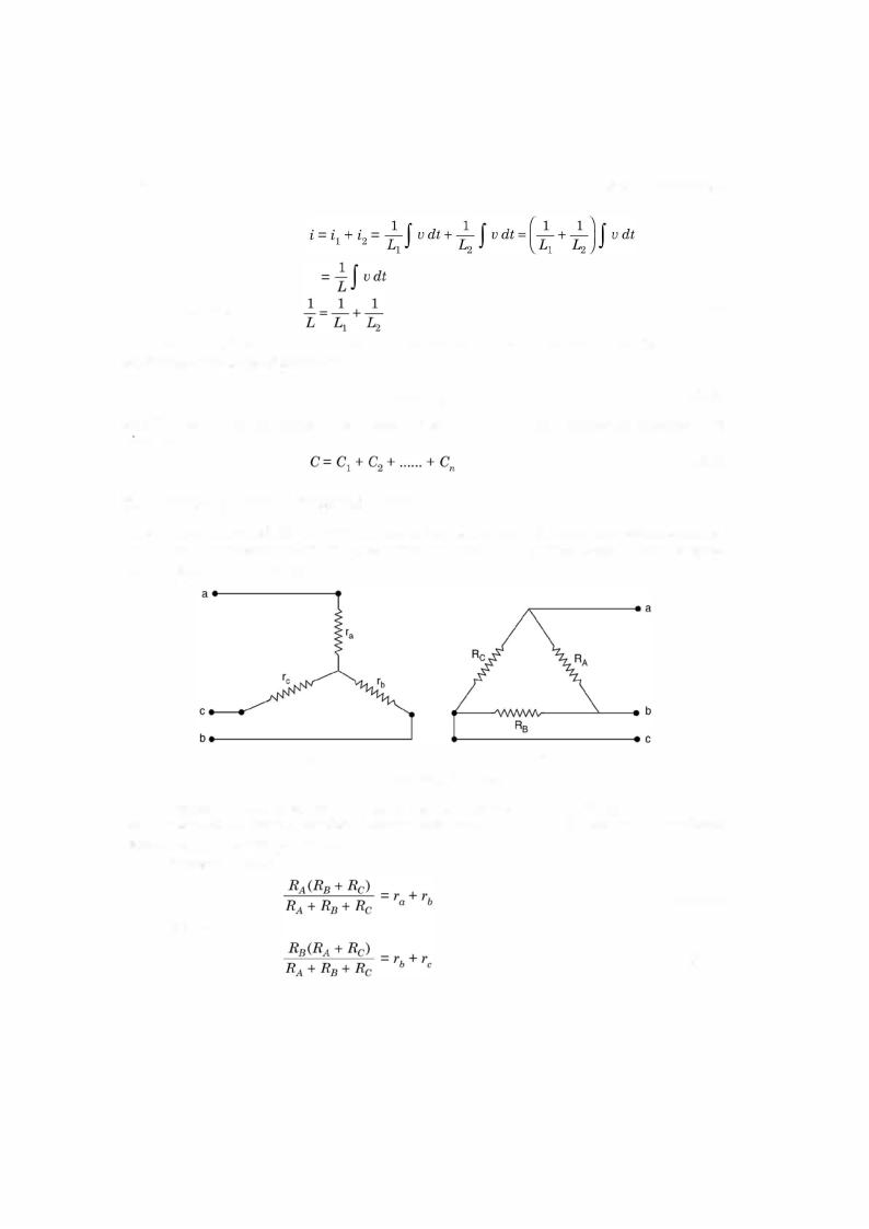
L = L1 + L2 + . . . . . . + Ln |
|
|
|
|||||||||||||
If two capacitors are connected in series then |
__C2!_i dt |
|
|||||||||||||||
|
|
= |
i |
|
|
2 |
|
__C1!_ |
i dt |
|
+ |
|
|||||
|
v |
= v |
|
+ v |
|
= |
|
|
|
i dt |
|
|
|
i dt |
|
||
|
|
(__C1!_ |
|
|
__C2!_) |
I |
|
|
= ]C_ |
J |
|
|
|||||
Therefore, |
1 |
1 |
+ |
|
1 |
|
|
I |
|
|
|
|
I |
|
...(2.6) |
||
-c |
= C1 |
+C2 |
|
|
|
|
|
|
|
||||||||
|
|
- |
|
- |
|
|
|
|
|
|
|
|
|
|
|||
|
|
|
|
|
|
|
|
|
|
|
|
|
|
|
|
||
Similarly by using KCL, law of parallel combination of these elements can be obtained. We will try here for inductors. Say there are two inductors connected in parallel.
From Fig. 2.4(a)
i L
(a) |
(b) |
Fig. 2.4 (a) Inductor in parallel (b) Equivalent of (a).