Basic_Electrical_Engineering_4th_edition
.pdf
296 |
ELECTRICAL ENGINEERING |
7.8APPLICATIONS
Synchronous motors have many advantages when a constant speed is desirable. Typical applica tions are to drive pumps, fans, and de generators. They can be operated at unity p.f., thus mini mising the line current. In sizes above 2000 hp synchronous motor's cost less than induction motors having static capacitors for p.f. correction. A major advantage of synchronous motors is
that it can be used as a phase modifier and hence it can take care ofthe overloading and no load
voltage variations by overexciting and underexciting itsfieldwinding respectively. Duringover excitation it draws leading current and thus corrects the overall p.f. of a plant having other equipment drawinglaggingcurrent.
Example 7.1. A 2300 V, 3-phase synchronous motor driving a pump is provided with a line ammeter and a field rheostat. When the rheostat is adjusted so that the ac line current is a minimum, the ammeter reads 8.8 A. What approximate power is being delivered to the pump ? How should the rheostat be adjusted so that the motor is operating at 0.8 pf lead ? How many KVArs is the motor supplying to the system at 0. 8 p.f lead ?
Solution. From the 'V' curve we know that for a given power, the current is minimum at unity p.f. Hence power drawn from .theJ3 line is .J3
p = VLIL = . 2300 . 8.8 = 35 kW
In order to obtain 0.8 lead p.f., the excitation current should be increased i.e. the field
rheostat resistance should be decreased such that the armature current I is given as |
|||
or |
.J3 |
v,, I cos <j> = 35000 |
|
I = |
.J3 2300 x 0.8 |
= 10.98 A = 11 Amp. |
|
|
|
35000 |
|
|
by the motor |
|
|
|
The kVAr suppliedJ3 VI sin <j> =xJ3 x 2300 x 1 1 x 0.8 |
||
|
|
= 26.29 kVAr. |
Ans. |
Example 7.2. A manufacturingplant presents an electrical load to the power system, of 5000 kW at 0. 8 p.f lag. It has been decided to replace a 500 hp induction motor that drives a pump. The motor operates at an efficiency of 96% and a p.f of 0.9 lag. Ifa synchronous motor is purchased as a replacement, which is capable ofoperating at 0.8 p.f lead. What will be the new plant p.f ? Assume the synchronous motor to have the same efficiency. What per cent decrease in line current will result from the improved p.f
Solution. |
5000 +j 5000 tan cos-1 0.8 |
|||
Original power (complex) |
||||
|
== 5000 + j 5000 |
x |
8 |
= 5000 + j 3750 kW |
|
|
|||
The power input to induction motor
500 x 735 = 382.8 kW
0.96
Hence complex power ofinduction motor
382.8 +j 382.8 tan cos-1 0.9
THREE-PHASE SYNCHRONOUS MACHINES |
299 |
|
The drop IZ8 |
(104.96 +j78.72)(0.093 +j8.5) |
|
|
||
|
9.76 +j892.6 +j7.32 - 669.12 - 659.36 +j899.92 |
|
Hence |
E = 3810 - 659.36 +j899.92 = 3150.64 +j899.92 |
|
|
E = 3276 Volts |
|
Hence % regulation |
= 3276 - 3810 x 100 |
|
|
3810 |
|
|
= - 14%. |
Ans. |
Howeverby usingapproximate expression |
||
Voltageregulation |
9.76669.12 x 100 |
|
|
= - |
|
|
3810 |
|
|
::::17%. |
Ans. |
Example 7.6. Ifa field excitation of 1 0 A in a certain alternator gives a current of 150 A on short circuit and a terminal voltage of 900 V on open circuit, find the internal voltage drop with a load current of 60 A.
Solution. By definition synchronous impedance |
||||
|
|
= |
Open circuit voltage for certain If |
|
|
|
|
|
S. C. current for same If |
|
|
|
900 |
|
|
|
s = -150 = 6 ! 1. |
||
|
|
= IZS |
|
|
|
drop |
|
|
|
The internal voltage |
z |
= |
|
= 60 x 6 |
360 Volts. Ans.
7.9STEPPER MOTOR
A stepper motor is a polyphase synchronous motor having salient statorpoles. The namestepper derives fromthe most common applicationforthese machines i.e. rotating a fixed angular stepin response to each input pulse received by their controller when this type ofmotor is fed from an electronic drive, accurate positioncontrol andprecise rotational speeds areobviouslyobtained.
Based onprinciple ofoperation, steppermotors may be dividedintothreecategories. These are, permanent magnet, variable reluctance and hybrid type which utilize both principle for torque development. Fig. 7.16 shows the three rotor types and their respective torque/displace ment characteristics.
7.9.1Permanent Magnet Type
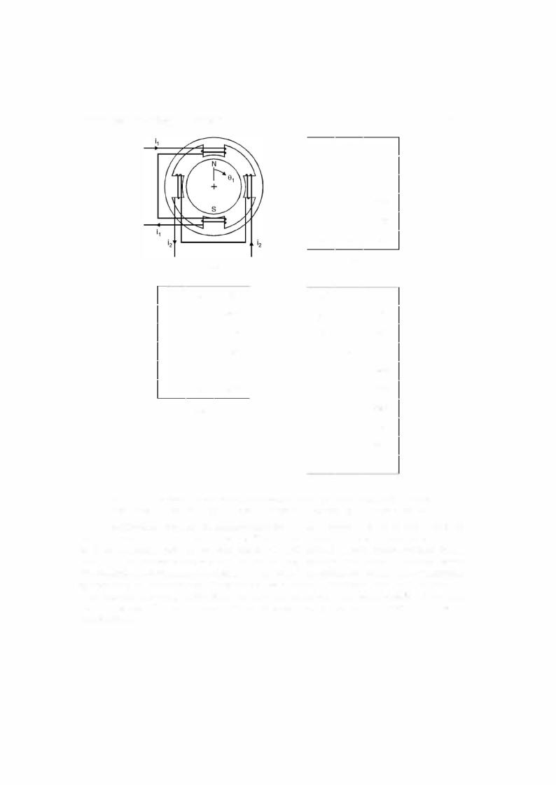
Considerthe simplifiedtwo-phase statorwithtwo-polepermanentmagnetrotor shownin Fig. 7.17. The rotor is shown in a stable equilibrium position for the case when i1 > 0 and i2 = 0. Stepping action is produced by switching current i1 and i2, supplied from a bipolar source. Three possible sequences forproducingclockwise rotation are given. The first energises onlyone phase winding

300 |
ELECTRICAL ENGINEERING |
(a)
(b)
(c)
Fig. 7.16. Torque development in the three basic types of stepper motors.
(a) Permanent-magnet rotor. (b) Variable reluctance rotor. (c) Hybrid rotor.
at a time. The resulting step size is one-half the pole pitch. The second method energises both simultaneouslyandwouldthusrequire larger power supply. The resulting steps are the same size, but the effective stator pole positions are located midwaybetweenthe pole pieces. Advan tages ofthis scheme are increased torque and damping. The final method, known as half-step ping, alternates between one andtwo phases. The resulting step size isone-fourththe pole.
Varioustechniques have beenusedtoproduce smallerstep sizes. Perhapsthe mostobvious is to increase the number ofpoles or the number ofphases orboth.
Bothpermanent magnet andvariable reluctance rotorcanbe used. However, a permanent magnet motorprovides smoothresponse.
THREE-PHASE SYNCHRONOUS MACHINES |
|
|
|
|
|
|
|
301 |
|||
|
|
|
|
|
ia |
|
i b |
8 1 |
|||
|
|
|
|
|
+ |
|
0 |
o |
|
||
|
|
|
|
|
|
90o° |
|||||
|
|
|
|
|
0 |
|
+ |
||||
|
|
|
|
|
|
|
|
0 |
1 80° |
||
|
|
|
|
|
|
a |
|
- |
|
1 |
|
|
|
|
|
|
0 |
|
(b) |
270° |
|||
|
|
|
(a) |
|
- |
|
O" |
||||
|
|
|
|
|
+ |
|
0 |
|
|
||
|
|
ia |
i p |
8 1 |
i |
|
|
i |
b |
8 |
|
|
|
+ |
+ |
|
+ |
|
|
o |
|
||
|
|
45° |
|
0 |
|
||||||
|
|
|
+ |
135° |
+ |
|
+ |
45o° |
|||
|
|
|
- |
225° |
0 |
|
+ |
90° |
|||
|
|
+ |
315° |
- |
|
+ |
1 35° |
||||
|
|
+ |
+ |
45° |
- |
|
0 |
1 80° |
|||
|
|
- |
(c) |
|
- |
|
- |
225° |
|||
|
|
- |
- |
|
0 |
|
|
|
270° |
||
|
|
|
|
|
+ |
|
(cf) |
31 5° |
|||
|
|
|
|
|
+ |
|
O" |
||||
|
|
|
|
|
|
0 |
|
|
|||
Fig. |
7.17. |
Two-phase permanent-magnet stepper motor. |
|
(a) |
Cross-section (b) Full-step. |
||||||
|
|
|
- |
|
|
||||||
single-winding sequence. (c) Full-step, two-winding sequence. |
(d) Half-step sequence. |
||||||||||
- |
|
|
|||||||||
An identical torque/speed characteristic for a stepper motor is shown in Fig. 7.18. Note that two modes of operations are possible. The normal mode could be called loched step. In this mode the combined load plus the rotor inertia is less than the developed torque, with the result that the rotor may come to rest (or at least experience a reversal ofmomentum) between steps. Starts, stops andinstantaneousreversals are possible. The second mode calledslewingmaintains synchronism but does not permit stops or reversals. Some applications utilise both modes e.g. a magnetic tape drive may read/write at a step rate in the normal mode but rewind/fast forwardin the slewing mode. Thetransitionto and from slewing musthe properlycontrolled to avoidloss of synchronism.

302 |
ELECTRICAL ENGINEERING |
Torque
Slew mode
Speed steps/min
Fig. 7.18. Typical speed-torque characteristic of stepper motor.
7.9.2Comparison of Stepper Motors
Steppermotors are availablewithstep sizes rangingfrom 90° to 0.72°. Maximum step rates vary from about 100 to as many as 10,000 per sec. Torque capacities varyover a wide range. Selection ofa stepper motorfor aparticularapplication must considertheoverall performance ofthe motor with electronic drive.
Permanent magnet steppers are available in the larger step sizes, usually about 5°. They exhibit excellent torque/volume ratios but typically have high inertia rotors. The rotor provides braking and holding torque even with the stator windings deenergised. The variable reluctance motor is ideally suitedto the smaller step sizes. By comparison, it develops less torque. However, since it may be constructed with a low inertia rotor, its torque/inertiaratio may be superior. The rotoris capable of"free-wheeling" sincebrakinganddetenttorque mustbe providedbythe stator. Thehybridsteppercombines the smaller step size ofthevariablereluctance rotorwiththehigher torque ofthe permanent magnet. Some braking and holding torque is also present. As might be expected, it is the most expensive ofthe three types to manufacture.
7.9.3Application
The characteristics ofsteppermotors make them ideally suited to many applications requiring incremental motion, especially where digitalcontrol is used. Afew common ones are printer head and paper feed drives in computer printers, disc drives, digitalplotters, medical equipment that dispenses precise dosages, computer controlledtools and process control valves.
7.1.
7.2. Explain why a synchronous motor is not self-starting.
7.3. What is a damper winding '? Explain its application for a synchronous motor.
7.4. Describe briefly the construction, principle of operation and application of a synchronous motor. Explain why a synchronous motor develops torque at synchronous speed whereas an induction motor develops torque at all speeds except the synchronous speed.