

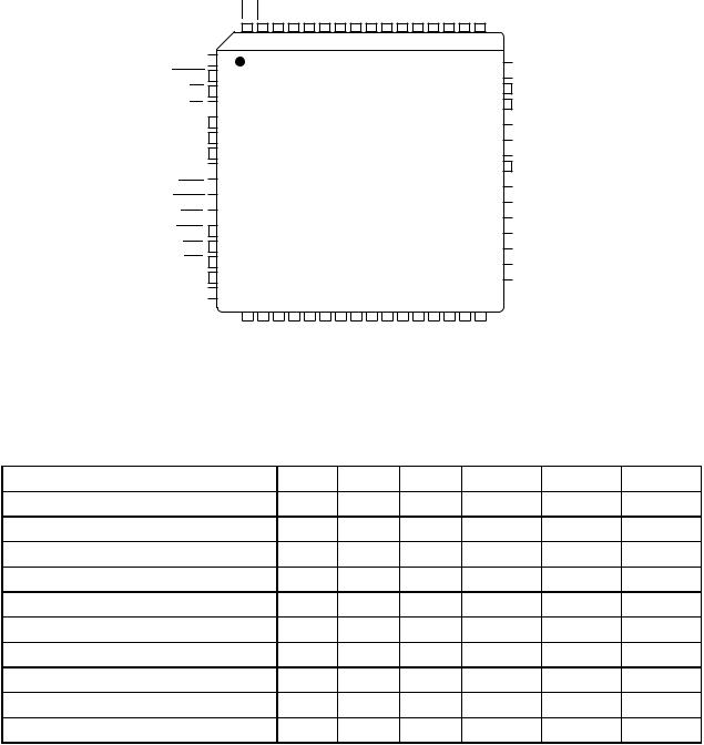
LDS
64
R/W 
 1
1
DTACK
BG
BR 

VCC
CLK
GND
MODE 
HALT 

RESET 
AVEC 
BERR
IPL2
IPL1
IPL0
FC2 
 16
16
17
FC1
UDS |
|
AS D0 D1 D2 D3 D4 GND |
D5 D6 D7 D8 D9 |
|
|||
|
MC68EC000
FC0 A0 A1 |
A2 A3 GND A4 A5 A6 |
A7 A8 A9 A10 |
D10
A11
D11
49
48  D12
D12
 D13 D14
D15
 A23
A23
 A22
A22
 A21
A21
VCC
 A20
A20
 A19
A19
 A18
A18
 A17
A17
 A16
A16
 A15
A15
 A14 33
  A13
A13
32
A12
Figure 11-6. 64-Lead Quad Flat Pack
11.2 PACKAGE DIMENSIONS
Case Package |
68000 68008 |
68010 |
68HC000 |
68HC001 68EC000 |
740-03 L Suffix |
|
|
|
|
767-02 P Suffix |
|
|
|
|
746-01 LC Suffix |
|
|
|
|
754-01 R and P Suffix |
|
|
|
|
765A-05 RC Suffix |
|
|
|
|
778-02 FN Suffix |
|
|
|
|
779-02 FN Suffix |
|
|
|
|
779-01 FN Suffix |
|
|
|
|
847-01 FC Suffix |
|
|
|
|
840B-01 FU Suffix |
|
|
|
|
MOTOROLA |
M68000 8-/16-/32-BIT MICROPROCESSORS USER'S MANUAL |
11-7 |
64 |
|
|
|
33 |
|
|
|
|
B |
1 |
|
|
|
32 |
|
|
|
A |
|
|
|
F |
|
C |
|
|
|
|
|
|
|
|
|
N |
|
D |
|
T |
K |
|
|
|
||
|
|
|
G |
|
|
|
|
|
NOTES:
1.DIMENSION -A- IS DATUM.
2.POSTIONAL TOLERANCE FOR LEADS:


 0.25 (0.010) M T A M
3.-T- IS SEATING PLANE
4.DIMENSION "L" TO CENTER OF LEADS WHEN FORMED PARALLEL.
5.DIMENSIONING AND TOLERANCING PER ANSI Y14.5m, 1982.
|
MILLIMETERS |
INCHES |
||
DIM |
MIN |
MAX |
MIN |
MAX |
A |
60.36 |
61.56 |
2.376 |
2.424 |
B |
14.64 |
15.34 |
0.576 |
0.604 |
C |
3.05 |
4.32 |
0.120 |
0.160 |
D |
3.81 |
0.533 |
0.015 |
0.021 |
F |
.762 |
1.397 |
0.030 |
0.055 |
G |
2.54 BSC |
0.100 BSC |
||
J |
0.204 |
0.330 |
0.008 |
0.013 |
K |
2.54 |
4.19 |
0.100 |
0.165 |
L |
15.24 BSC |
0.600 BSC |
||
M |
0 |
10 |
0 |
10 |
N |
1.016 |
1.524 |
0.040 |
0.060 |
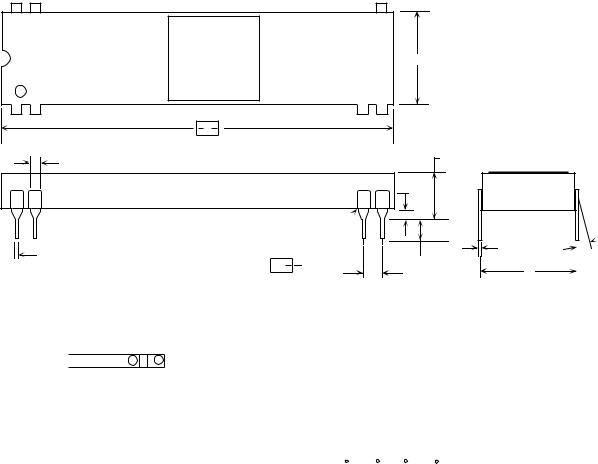
Figure 11-7. Case 740-03—L Suffix
L SUFFIX 746-03
 M
M
J
L
11-8 |
M68000 8-/16-/32-BIT MICROPROCESSORS USER'S MANUAL |
MOTOROLA |
R |
|
|
A |
48 |
25 |
B
1 |
24 |
 C
C
 N
N

 T
T 

|
|
|
|
|
|
|
|
|
|
|
|
|
|
|
|
|
|
|
|
|
|
|
|
|
|
|
|
|
|
|
H |
|
|
|
|
|
G |
|
|
|
|
|
F |
|
|
|
|
D |
|
|
|
|
|
|
K |
||||
|
|
|
|
|
|
|
|
|
|
|
|
|
|
|
|
|
|
|
|
|
|||||||||
|
|
|
|
|
|
|
|
|
|
|
|
|
|
|
|
|
|
|
|
|
|
|
|||||||
|
|
|
|
|
|
|
|
|
|
|
|
|
|
|
|
|
|
|
|
|
|
|
|
|
|
|
|
|
|
NOTES: |
|
|
|
|
|
|
|
|
|
|
|
|
|
|
|
|
|
|
MILLIMETERS |
|
INCHES |
||||||||
|
1. -R- IS END OF PACKAGE DATUM PLANE |
|
|
|
|
|
|
|
DIM |
MIN |
MAX |
|
MIN |
|
MAX |
||||||||||||||
|
|
|
|
|
|
|
|
A |
61.34 |
62.10 |
2.415 |
|
2.445 |
||||||||||||||||
|
|
-T- IS BOTH A DATUM AND SEATING PLANE |
|
|
|
|
|
|
|
|
|||||||||||||||||||
|
|
|
|
|
|
|
|
|
B |
13.72 |
14.22 |
0.540 |
|
0.560 |
|||||||||||||||
2. POSITIONAL TOLERANCE FOR LEADS 1 AND |
|
|
|
|
|
|
|
|
|||||||||||||||||||||
48. |
|
|
|
|
|
|
|
|
|
|
|
|
|
|
|
|
|
|
C |
3.94 |
5.08 |
0.155 |
|
0.200 |
|||||
|
|
|
0.51 (0.020) |
T |
B M |
R |
|
|
|
|
|
|
|
|
|
|
|
|
|
D |
0.36 |
0.55 |
0.014 |
|
0.022 |
||||
|
|
|
|
|
|
|
|
|
|
|
|
|
|
|
|
|
|||||||||||||
|
POSITIONAL TOLERANCE FOR LEAD |
|
|
|
|
|
|
|
F |
1.02 |
1.52 |
0.040 |
|
0.060 |
|||||||||||||||
|
PATTERN; |
|
|
|
|
|
|
|
|
|
|
|
|
|
|
|
|
|
G |
2.54 BSC |
|
0.100 BSC |
|||||||
|
|
|
0.25 (0.020) |
T |
B M |
|
|
|
|
|
|
|
|
|
|
|
|
|
|
H |
1.79 BSC |
|
0.070 BSC |
||||||
|
|
|
|
|
|
|
|
|
|
|
|
|
|
|
|
|
|||||||||||||
3. DIMENSION "A" AND "B" DOES NOT INCLUDE MOLD FLASH, |
J |
0.20 |
0.38 |
0.008 |
|
0.015 |
|||||||||||||||||||||||
|
MAXIMUM MOLD FLASH 0.25 (0.010). |
|
|
|
|
|
|
|
K |
2.92 |
3.81 |
0.115 |
|
0.135 |
|||||||||||||||
4. DIMENSION "L" IS TO CENTER OF LEADS WHEN FORMED |
|
|
L |
15.24 BSC |
|
0.600 BSC |
|||||||||||||||||||||||
|
PARALLEL. |
|
|
|
|
|
|
|
|
|
|
|
|
|
|
|
|
|
|
||||||||||
5. DIMENSIONING AND TOLERANCING PER ANSI Y14.5, 1982. |
|
|
M |
0 |
15 |
0 |
|
15 |
|||||||||||||||||||||
6. CONTROLLING DIMENSION: INCH. |
|
|
|
|
|
|
|
N |
0.51 |
1.02 |
0.020 |
|
0.040 |
||||||||||||||||
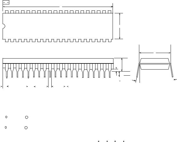
Figure 11-8. Case 767-02—P Suffix
P SUFFIX 767-02
L
 M J
M J

MOTOROLA |
M68000 8-/16-/32-BIT MICROPROCESSORS USER'S MANUAL |
11-9 |
|
|
|
|
|
|
|
|
|
|
|
|
|
|
|
|
|
|
|
|
|
|
|
|
|
|
|
|
|
|
|
|
|
|
|
|
|
|
|
|
|
|
|
|
|
|
|
|
|
|
|
|
|
64 |
|
|
|
|
|
|
|
|
|
|
|
|
|
|
|
|
|
|
|
|
|
|
|
|
|
|
|
|
|
|
33 |
|
|
|
|
|
|
|
|
|
|
|
|
|
||||||
|
|
|
|
|
|
|
|
|
|
|
|
|
|
|
|
|
|
|
|
|
|
|
|
|
|
|
|
|
|
|
|
|
|
|
|
|
|
|
|
|
|
|
|
|
|
|
|
|
|
|
|
|
|
|
|
|
|
|
|
|
|
|
|
|
|
|
|
|
|
|
|
|
|
|
|
|
|
|
|
|
|
|
|
|
|
|
|
|
|
|
|
|
|
|
|
|
B |
||||||
|
1 |
|
|
|
|
|
|
|
|
|
|
|
|
|
|
|
|
|
|
|
|
|
|
|
|
|
|
|
|
|
|
|
|
32 |
|
|
|
|
|
|
|
|
|
|
|
|
|
||||
|
|
|
|
|
|
|
|
|
|
|
|
|
|
|
|
|
|
|
|
|
|
|
|
|
|
|
|
|
|
|
|
|
|
|
|
|
|
|
|
|
|
|
|
|
|
||||||
|
|
|
|
|
|
|
|
|
|
|
|
|
|
|
|
|
|
|
|
|
|
|
|
|
|
|
|
|
|
|
|
|
|
|
|
|
|
|
|
|
|
|
|
|
|
|
|
|
|
|
|
|
|
|
|
|
|
|
|
|
|
|
|
|
|
|
|
|
|
|
|
|
|
|
|
|
|
|
|
|
|
|
|
|
|
|
|
|
|
|
|
|
|
|
|
|
|
|
|
|
|
|
|
|
|
|
|
|
|
|
|
|
|
|
|
|
|
|
|
|
|
|
|
|
A |
|
|
|
|
|
|
|
|
|
|
|
|
|
|
|
|
|
|
|
|
|
|
|
|
|
|
|
|
C |
|
|
|
|
|
|
|
|
|
|
|
|
|
|
|
|
|
|
|
|
|
|
|
|
|
|
|
|
|
|
|
|
|
|
|
|
|
|
|
|
|
|
|
|
|
|
|
|
|
|
|||
|
|
|
|
|
|
|
|
|
|
|
F |
|
|
|
|
|
|
|
|
|
|
|
|
|
|
|
|
|
|
|
|
|
|
|
|
||||||||||||||||
|
|
|
|
|
|
|
|
|
|
|
|
|
|
|
|
|
|
|
|
|
|
|
|
|
|
|
|
|
|
|
|
|
|
|
|||||||||||||||||
|
|
|
|
|
|
|
|
|
|
|
|
|
|
|
|
|
|
|
|
|
|
|
|
|
|
|
|
|
|
|
|
|
|
|
|||||||||||||||||
|
|
|
|
|
|
|
|
|
|
|
|
|
|
|
|
|
|
|
|
|
|
|
|
|
|
|
|
|
|
|
|
|
|
|
|
|
|||||||||||||||
|
|
|
|
|
|
|
|
|
|
|
|
|
|
|
|
|
|
|
|
|
|
|
|
|
|
|
|
|
|
|
|
|
|
|
|
|
|
|
|
|
|
|
N |
|
|
|
|
|
|
|
|
|
|
|
|
|
|
|
|
|
|
|
|
|
|
|
|
|
|
|
|
|
|
|
|
|
|
|
|
|
|
|
|
|
|
|
|
|
|
|
|
|
|
|
|
|
|
|
|
|
|
||
|
|
|
|
|
|
|
|
|
|
|
|
|
|
|
|
|
|
|
|
|
|
|
|
|
|
|
|
|
|
|
|
|
|
|
|
|
|
|
|
|
|
|
|
|
|
|
|
|
|
|
|
|
|
|
|
|
|
|
|
D |
|
|
|
|
|
|
|
|
|
|
|
|
|
|
|
|
|
|
|
|
|
|
|
|
|
|
|||||||||||||||||
|
|
|
|
|
|
|
|
|
|
|
|
|
|
|
|
|
|
|
|
|
|
|
|
|
|
|
|
|
|
|
|
|
|
||||||||||||||||||
|
|
|
|
|
|
|
|
|
|
|
|
|
|
|
|
|
|
|
|
|
|
|
|
|
|
|
|
|
|
|
|
|
|
||||||||||||||||||
|
|
|
|
|
|
|
|
|
|
|
|
|
|
|
|
|
|
|
|
|
|
|
|
|
|
|
|
|
|
|
|
|
|
||||||||||||||||||
|
|
|
|
|
|
|
|
|
|
|
|
|
|
|
|
|
|
|
|
|
|
|
|
|
|
|
T |
|
|
|
|
|
|
|
|
G |
|
|
|
|
|
|
|
|
K |
||||||
|
|
|
|
|
|
|
|
|
|
|
|
|
|
|
|
|
|
|
|
|
|
|
|
|
|
|
|
|
|
|
|
|
|
|
|
|
|
|
|
|
|
|
|
|
|
|
|
|
|||
|
|
|
|
|
|
|
|
|
|
|
|
|
|
|
|
|
|
|
|
|
|
|
|
|
|
|
|
|
|
|
|
|
|
|
|
|
|
|
|
|
|
||||||||||
|
|
|
|
|
|
|
|
|
|
NOTES: |
|
|
|
|
|
|
|
MILLIMETERS |
|
|
|
INCHES |
|
||||||||||||||||||||||||||||
|
|
|
|
|
|
|
|
|
|
1. DIMENSION -A- IS DATUM. |
|
|
|
|
|
|
DIM |
MIN |
|
MAX |
|
MIN |
|
|
MAX |
|
|||||||||||||||||||||||||
|
|
|
|
|
|
|
|
|
|
|
2. POSTIONAL TOLERANCE FOR LEADS: |
|
|
|
|
|
|
A |
80.52 |
82.04 |
|
3.170 |
|
3.230 |
|
||||||||||||||||||||||||||
|
|
|
|
|
|
|
|
|
|
|
|
|
|
0.25 (0.010) M |
T |
A M |
|
|
|
|
|
|
|
|
|
|
|
|
|
|
|
B |
22.25 |
22.96 |
|
0.876 |
|
0.904 |
|
||||||||||||
|
|
|
|
|
|
|
|
|
|
|
|
|
|
|
|
|
|
|
|
|
|
|
|
|
|
|
|
|
|
|
|
||||||||||||||||||||
|
|
|
|
|
|
|
|
|
|
|
3. -T- IS SEATING PLANE |
|
|
|
|
|
|
|
|
|
|
|
|
|
|
|
|
||||||||||||||||||||||||
|
|
|
|
|
|
|
|
|
|
|
|
|
|
|
|
|
C |
3.05 |
4.32 |
|
|
0.120 |
|
0.160 |
|
||||||||||||||||||||||||||
|
|
|
|
|
|
|
|
|
|
4. DIMENSION "L" TO CENTER OF LEADS |
|
|
|
|
|
|
D |
0.38 |
0.53 |
|
0.015 |
|
0.021 |
|
|||||||||||||||||||||||||||
|
|
|
|
|
|
|
|
|
|
|
WHEN FORMED PARALLEL. |
|
|
|
|
|
|
F |
.76 |
|
1.40 |
|
|
0.030 |
|
0.055 |
|
||||||||||||||||||||||||
|
|
|
|
|
|
|
|
|
|
5. DIMENSIONING AND TOLERANCING PER |
|
|
|
|
|
|
|
|
|
|
|
||||||||||||||||||||||||||||||
|
|
|
|
|
|
|
|
|
|
|
|
|
|
|
|
G |
2.54 BSC |
|
0.100 BSC |
|
|||||||||||||||||||||||||||||||
|
|
|
|
|
|
|
|
|
|
|
ANSI Y14.5, 1973. |
|
|
|
|
|
|
|
|
||||||||||||||||||||||||||||||||
|
|
|
|
|
|
|
|
|
|
|
|
|
|
|
|
|
|
|
|
|
|
|
|
|
|
|
|
|
|
|
|
J |
0.20 |
0.33 |
|
|
0.008 |
|
0.013 |
|
|||||||||||
|
|
|
|
|
|
|
|
|
|
|
|
|
|
|
|
|
|
|
|
|
|
|
|
|
|
|
|
|
|
|
|
K |
2.54 |
4.19 |
|
0.100 |
|
0.165 |
|
||||||||||||
|
|
|
|
|
|
|
|
|
|
|
|
|
|
|
|
|
|
|
|
|
|
|
|
|
|
|
|
|
|
|
|
L |
22.61 |
23.11 |
|
0.890 |
|
0.910 |
|
||||||||||||
|
|
|
|
|
|
|
|
|
|
|
|
|
|
|
|
|
|
|
|
|
|
|
|
|
|
|
|
|
|
|
|
M |
0 |
10 |
|
|
0 |
|
|
10 |
|
|
|||||||||
|
|
|
|
|
|
|
|
|
|
|
|
|
|
|
|
|
|
|
|
|
|
|
|
|
|
|
|
|
|
|
|
N |
1.02 |
1.52 |
|
|
0.040 |
|
0.060 |
|
|||||||||||
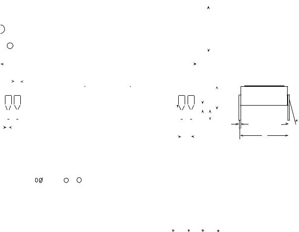
Figure 11-9. Case 746-01—LC Suffix
L SUFFIX 746-01
 M
M
J
L
11-10 |
M68000 8-/16-/32-BIT MICROPROCESSORS USER'S MANUAL |
MOTOROLA |
64 33
|
|
|
|
|
|
|
|
|
|
|
|
|
|
|
|
|
|
|
|
|
|
B |
||||
1 |
|
|
|
|
|
|
|
|
32 |
|
|
|
|
|
|
|
|
|
||||||||
|
|
|
|
|
|
|
|
|
|
|
|
|
|
|
|
|
|
|
|
|||||||
|
|
|
|
|
|
|
|
|
|
|
A |
|
|
|
|
|
|
|
|
|
|
|
|
|
|
C |
|
|
|
|
|
|
|
|
|
|
|
|
|
|
|
|
|
|
|
|
|
|
|
|
|
||
|
|
|
|
|
|
|
|
|
|
F |
|
|
|
|
|
|
|
|
|
|
|
|
|
|
||
|
|
|
|
|
|
|
|
|
|
|
|
|
|
|
|
|
|
|
|
|
|
|
|
|
||
|
|
|
|
|
|
|
|
|
|
|
|
|
|
|
|
|
|
|
|
|
|
|
|
|
||
|
|
|
|
|
|
|
|
|
|
|
|
|
|
|
|
|
|
|
|
|
|
|
|
|
||
|
|
|
|
|
|
|
|
|
|
|
|
|
|
|
|
|
|
|
|
|
|
|
|
|
||
|
|
|
|
|
|
|
|
|
|
|
|
|
|
|
|
|
|
|
|
|
|
N |
|
|
||
|
|
|
|
|
|
|
|
|
|
|
|
|
|
|
|
|
|
|
|
|
|
|
|
|||
|
|
|
|
|
|
|
|
|
|
|
|
|
|
|
|
|
|
|
|
|
|
|
|
|||
|
|
|
|
|
|
|
|
|
|
|
|
|
|
|
|
|
|
|
|
|
|
|
|
|
|
|
|
|
|
|
|
|
|
|
|
|
|
|
|
|
|
|
|
|
|
|
|
|
|
|
|
|
|
|
|
|
|
|
|
|
|
|
|
|
|
|
|
|
|
|
|
|
|
|
|
|
|
|
|
|
|
T |
|
|
|
|
|
|
|
|
|
|
|
|
|
|
|
|
|
|
|
|
|
|
|
|
|
|
|
|
|
|
|
|
|||
|
|
|
|
|
|
|
|
|
|
|
|
|
|
|
|
|
|
|
|
|
|
|
|
|
|
|
|
|
|
|
|
|
|
|
|
|
|
|
|
D |
|
|
|
|
G |
|
|
|
|
|
K |
||||||||||||
|
|
|
|
|
|
|
|
|
|
|
|
|
|
|
|
|
|||||||||||||||
|
|
|
|
|
|
|
|
|
|
|
|
|
|
|
|
|
|||||||||||||||
|
|
|
|
|
|
|
|
|
|
|
|
|
|
|
|
|
|||||||||||||||
|
|
|
|
|
|
|
|
|
|
|
|
|
|
|
|
|
|
|
|
|
|
|
|
||||||||
|
|
|
|
|
|
|
|
|
|
|
|
|
|
|
|
|
|
|
|
|
|
|
|||||||||
NOTES: |
|
|
|
|
|
|
|
|
|
|
|
|
|
|
|
|
|
|
|||||||||||||
1. DIMENSIONS A AND B ARE DATUMS. |
|
MILLIMETERS |
|
INCHES |
|
|
|
||||||||||||||||||||||||
2. -T- IS SEATING PLANE. |
DIM |
|
MIN |
MAX |
|
MIN |
|
MAX |
|
|
|
||||||||||||||||||||
A |
81.16 |
81.91 |
3.195 |
|
3.225 |
|
|
|
|
||||||||||||||||||||||
3. POSITIONAL TOLERANCE FOR LEADS |
|
|
|
|
|
||||||||||||||||||||||||||
B |
20.17 |
20.57 |
0.790 |
|
0.810 |
|
|
|
|
||||||||||||||||||||||
(DIMENSION D): |
|
|
|
|
|
||||||||||||||||||||||||||
C |
4.83 |
5.84 |
0.190 |
|
0.230 |
|
|
|
|
||||||||||||||||||||||
|
|
0.25 (0.010) M |
T |
A M |
B M |
|
|
|
|
|
|
|
|||||||||||||||||||
|
|
|
D |
0.33 |
0.53 |
0.013 |
|
0.021 |
|
|
|
|
|||||||||||||||||||
4. DIMENSION B DOES NOT INCLUDEMOLD FLASH. |
|
|
|
|
|
|
|||||||||||||||||||||||||
|
F |
1.27 |
1.77 |
0.050 |
|
0.070 |
|
|
|
|
|||||||||||||||||||||
5. DIMENSION L IS TO CENTER OF LEADS WHEN FORMED |
|
|
|
|
|
||||||||||||||||||||||||||
PARALLEL. |
G |
|
2.54 BSC |
|
0.100 BSC |
|
|
|
|||||||||||||||||||||||
6. DIMENSIONING AND TOLERANCING PER ANSI Y14.5, 1982. |
J |
0.20 |
0.38 |
0.008 |
|
0.015 |
|
|
|
|
|||||||||||||||||||||
|
|
|
|
|
|
|
|
|
|
|
|
|
|
K |
3.05 |
3.55 |
0.120 |
|
0.140 |
|
|
|
|
||||||||
|
|
|
|
|
|
|
|
|
|
|
|
|
|
L |
|
22.86 BSC |
|
0.9 00 BSC |
|
|
|
||||||||||
|
|
|
|
|
|
|
|
|
|
|
|
|
|
M |
0 |
|
15 |
0 |
|
|
15 |
|
|
|
|
|
|||||
|
|
|
|
|
|
|
|
|
|
|
|
|
|
N |
0.51 |
1.02 |
0.020 |
|
0.040 |
|
|
|
|
||||||||
Figure 11-10. Case 754-01—R and P Suffix
P SUFFIX 754-01
L
 M J
M J

MOTOROLA |
M68000 8-/16-/32-BIT MICROPROCESSORS USER'S MANUAL |
11-11 |
Figure 11-11. Case 765A-05—RC Suffix
11-12 |
M68000 8-/16-/32-BIT MICROPROCESSORS USER'S MANUAL |
MOTOROLA |
APPENDIX A
MC68010 LOOP MODE OPERATION
In the loop mode of the MC68010, a single instruction is executed repeatedly under control of the test condition, decrement, and branch (DBcc) instruction without any instruction fetch bus cycles. The execution of a single-instruction loop without fetching an instruction provides a highly efficient means of repeating an instruction because the only bus cycles required are those that read and write the operands.
The DBcc instruction uses three operands: a loop counter, a branch condition, and a branch displacement. When this instruction is executed in the loop mode, the value in the low-order word of the register specified as the loop counter is decremented by one and compared to minus one. If the result after decrementing the value is equal to minus one, the result is placed in the loop counter, and the next instruction in sequence is executed. Otherwise, the condition code register is checked against the specified branch condition. If the branch condition is true, the result is discarded, and the next instruction in sequence is executed. When the count is not equal to minus one and the branch condition is false, the branch displacement is added to the value in the program counter, and the instruction at the resulting address is executed.
Figure A-1 shows the source code of a program fragment containing a loop that executes in the loop mode in the MC68010. The program moves a block of data at address SOURCE to a block starting at address DEST. The number of words in the block is labeled LENGTH. If any word in the block at address SOURCE contains zero, the move operation stops, and the program performs whatever processing follows this program fragment.
|
LEA |
SOURCE, A0 |
Load A Pointer To Source Data |
|
LEA |
DEST, A1 |
Load A Pointer To Destination |
|
MOVE.W |
#LENGTH, D0 |
Load The Counter Register |
LOOP |
MOVE.W |
(A0);pl, (A1)+ |
Loop To Move The Block Of Data |
|
DBEQ |
D0, LOOP |
Stop If Data Word Is Zero |
Figure A-1. DBcc Loop Mode Program Example
The first load effective address (LEA) instruction loads the address labeled SOURCE into address register A0. The second instruction, also an LEA instruction, loads the address labeled DEST into address register A1. Next, a move data from source to destination (MOVE) instruction moves the number of words into data register D0, the loop counter.
The last two instructions, a MOVE and a test equal, decrement, and branch (DBEQ), form the loop that moves the block of data. The bus activity required to execute these instructions consists of the following cycles:
MOTOROLA |
M68000 8-/16-/32-BIT MICROPROCESSORS USER’S MANUAL |
A-1 |
1.Fetch the MOVE instruction.
2.Fetch the DBEQ instruction.
3.Read the operand at the address in A0.
4.Write the operand at the address in A1.
5.Fetch the displacement word of the DBEQ instruction.
Of these five bus cycles, only two move the data. However, the MC68010 has a two-word prefetch queue in addition to the one-word instruction decode register. The loop mode uses the prefetch queue and the instruction decode register to eliminate the instruction fetch cycles. The processor places the MOVE instruction in the instruction decode register and the two words of the DBEQ instruction in the prefetch queue. With no additional opcode fetches, the processor executes these two instructions as required to move the entire block or to move all nonzero words that precede a zero.
The MC68010 enters the loop mode automatically when the conditions for loop mode operation are met. Entering the loop mode is transparent to the programmer. The conditions are that the loop count and branch condition of the DBcc instruction must result in looping, the branch displacement must be minus four, and the branch must be to a oneword loop mode instruction preceding the DBcc instruction. The looped instruction and the first word of the DBcc instruction are each fetched twice when the loop is entered. When the processor fetches the looped instruction the second time and determines that the looped instruction is a loop mode instruction, the processor automatically enters the loop mode, and no more instruction fetches occur until the count is exhausted or the loop condition is true.
In addition to the normal termination conditions for the loop, several abnormal conditions cause the MC68010 to exit the loop mode. These abnormal conditions are as follows:
•Interrupts
•Trace Exceptions
•Reset Operations
•Bus Errors
Any pending interrupt is taken after each execution of the DBcc instruction, but not after each execution of the looped instruction. Taking an interrupt exception terminates the loop mode operation; loop mode operation can be restarted on return from the interrupt handler. While the T bit is set, a trace exception occurs at the end of both the looped instruction and the DBcc instruction, making loop mode unavailable while tracing is enabled. A reset operation aborts all processing, including loop mode processing. A bus error during loop mode operation is handled the same as during other processing; however, when the return from exception (RTE) instruction continues execution of the looped instruction, the three-word loop is not fetched again.
Table A-1 lists the loop mode instructions of the MC68010. Only one-word versions of these instructions can operate in the loop mode. One-word instructions use the three address register indirect modes: (An), (An)+, and –(An).
A-2 |
M68000 8-/16-/32-BIT MICROPROCESSORS USER’S MANUAL |
MOTOROLA |

Table A-1. MC68010 Loop Mode Instructions
Opcodes |
Applicable Addressing Modes |
MOVE [BWL] |
(Ay) to (Ax) |
|
(Ay) to (Ax)+ |
|
(Ay) to –(Ax) |
|
(Ay)+ to (Ax) |
|
(Ay)+ to –(Ax) |
|
–(Ay) to (Ax) |
|
–(Ay) to (Ax)+ |
|
–(Ay) to –(Ax) |
|
Ry to (Ax) |
|
Ry to (Ax)+ |
ADD [BWL] |
(Ay) to Dx |
AND [BWL] |
(Ay)+ to Dx |
CMP [BWL] |
–(Ay) to Dx |
OR [BWL] |
|
SUB [BWL] |
|
ADDA [WL] |
(Ay) to Ax |
CMPA [WL] |
–(Ay) to Ax |
SUBA [WL] |
(Ay)+ to Ax |
ADD [BWL] |
Dx to (Ay) |
AND [BWL] |
Dx to (Ay)+ |
EOR [BWL] |
Dx to –(Ay) |
OR [BWL] |
|
SUB [BWL] |
|
ABCD [B] |
–(Ay) to –(Ax) |
ADDX [BWL] |
|
SBCD [B] |
|
SUBX [BWL] |
|
CMP [BWL] |
(Ay)+ to (Ax)+ |
CLR [BWL] |
(Ay) |
NEG [BWL] |
(Ay)+ |
NEGX [BWL} |
–(Ay) |
NOT [BWL] |
|
TST [BWL] |
|
NBCD [B] |
|
ASL [W] |
(Ay) by #1 |
ASR [W] |
(Ay)+ by #1 |
LSL [W] |
–(Ay) by #1 |
LSR [W] |
|
ROL [W] |
|
ROR [W] |
|
ROXL [W] |
|
ROXR |
|
NOTE: [B, W, or L] indicate an operand size of byte, word, or long word.
MOTOROLA |
M68000 8-/16-/32-BIT MICROPROCESSORS USER’S MANUAL |
A-3 |