- •Table of Contents
- •List of Illustrations
- •List of Tables
- •2.1 Programmer's Model
- •2.1.2 Supervisor Programmer's Model
- •2.1.3 Status Register
- •2.2 Data Types and Addressing Modes
- •2.3 Data Organization in Registers
- •2.3.1 Data Registers
- •2.3.2 Address Registers
- •2.4 Data Organization in Memory
- •2.5 Instruction Set Summary
- •3.1 Address Bus
- •3.2 Data Bus
- •3.3 Asynchronous Bus Control
- •3.4 Bus Arbitration Control
- •3.6 System Control
- •3.7 M6800 Peripheral Control
- •3.11 Signal Summary
- •4.1 Data Transfer Operations
- •4.1.1 Read Cycle
- •4.1.2 Write Cycle
- •4.2 Other Bus Operations
- •5.1 Data Transfer Operations
- •5.1.1 Read Cycle
- •5.1.2 Write Cycle
- •5.1.4 CPU Space Cycle
- •5.2 Bus Arbitration
- •5.2.1 Requesting the Bus
- •5.2.2 Receiving the Bus Grant
- •5.3 Bus Arbitration Control
- •5.4 Bus Error and Halt Operation
- •5.4.1 Bus Error Operation
- •5.4.2 Retrying the Bus Cycle
- •5.4.4 Double Bus Fault
- •5.5 Reset Operation
- •5.7 Asynchronous Operation
- •5.8 Synchronous Operation
- •6.1 Privilege Modes
- •6.1.1 Supervisor Mode
- •6.1.2 User Mode
- •6.1.3 Privilege Mode Changes
- •6.1.4 Reference Classification
- •6.2 Exception Processing
- •6.2.1 Exception Vectors
- •6.2.2 Kinds of Exceptions
- •6.2.3 Multiple Exceptions
- •6.2.4 Exception Stack Frames
- •6.2.5 Exception Processing Sequence
- •6.3 Processing of Specific Exceptions
- •6.3.1 Reset
- •6.3.2 Interrupts
- •6.3.3 Uninitialized Interrupt
- •6.3.4 Spurious Interrupt
- •6.3.5 Instruction Traps
- •6.3.6 Illegal and Unimplemented Instructions
- •6.3.7 Privilege Violations
- •6.3.8 Tracing
- •6.3.9 Bus Error
- •6.3.10 Address Error
- •7.1 Operand Effective Address Calculation Times
- •7.2 Move Instruction Execution Times
- •7.3 Standard Instruction Execution Times
- •7.4 Immediate Instruction Execution Times
- •7.5 Single Operand Instruction Execution Times
- •7.6 Shift/Rotate Instruction Execution Times
- •7.7 Bit Manipulation Instruction Execution Times
- •7.8 Conditional Instruction Execution Times
- •7.9 JMP, JSR, LEA, PEA, and MOVEM Instruction Execution Times
- •7.10 Multiprecision Instruction Execution Times
- •7.11 Miscellaneous Instruction Execution Times
- •7.12 Exception Processing Execution Times
- •8.1 Operand Effective Address Calculation Times
- •8.2 Move Instruction Execution Times
- •8.3 Standard Instruction Execution Times
- •8.4 Immediate Instruction Execution Times
- •8.5 Single Operand Instruction Execution Times
- •8.6 Shift/Rotate Instruction Execution Times
- •8.7 Bit Manipulation Instruction Execution Times
- •8.8 Conditional Instruction Execution Times
- •8.9 JMP, JSR, LEA, PEA, and MOVEM Instruction Execution Times
- •8.10 Multiprecision Instruction Execution Times
- •8.11 Miscellaneous Instruction Execution Times
- •8.12 Exception Processing Execution Times
- •9.1 Operand Effective Address Calculation Times
- •9.2 Move Instruction Execution Times
- •9.3 Standard Instruction Execution Times
- •9.4 Immediate Instruction Execution Times
- •9.5 Single Operand Instruction Execution Times
- •9.6 Shift/Rotate Instruction Execution Times
- •9.7 Bit Manipulation Instruction Execution Times
- •9.8 Conditional Instruction Execution Times
- •9.10 Multiprecision Instruction Execution Times
- •9.11 Miscellaneous Instruction Execution Times
- •9.12 Exception Processing Execution Times
- •10.1 Maximum Ratings
- •10.2 Thermal Characteristics
- •10.3 Power Considerations
- •10.4 CMOS Considerations
- •10.5 AC Electrical Specification Definitions
- •10.6 MC68000/68008/68010 DC Electrical Characteristics
- •10.7 DC Electrical Characteristics
- •10.13 MC68EC000 DC Electrical Specifications
- •11.1 Pin Assignments
- •11.2 Package Dimensions
S0 |
S2 |
S4 |
S6 |
S0 |
S2 |
S4 |
S6 |
CLK
FC2–FC0
A23–A1
AS
UDS
LDS
R/W
DTACK
D0–D15
BERR
HALT
READ HALT RETRY
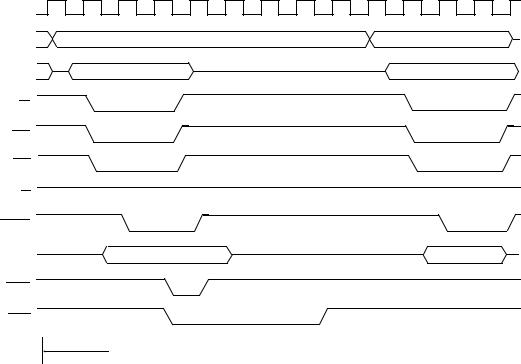
Figure 5-29. Halt Operation Timing Diagram
While the processor is halted, the address bus and the data bus signals are placed in the high-impedance state. Bus arbitration is performed as usual. Should a bus error occur while HALT is asserted, the processor performs the retry operation previously described.
The single-step mode is derived from correctly timed transitions of HALT. HALT is negated to allow the processor to begin a bus cycle, then asserted to enter the halt mode when the cycle completes. The single-step mode proceeds through a program one bus cycle at a time for debugging purposes. The halt operation and the hardware trace capability allow tracing of either bus cycles or instructions one at a time. These capabilities and a software debugging package provide total debugging flexibility.
5.4.4 Double Bus Fault
When a bus error exception occurs, the processor begins exception processing by stacking information on the supervisor stack. If another bus error occurs during exception processing (i.e., before execution of another instruction begins) the processor halts and asserts HALT. This is called a double bus fault. Only an external reset operation can restart a processor halted due to a double bus fault.
A retry operation does not initiate exception processing; a bus error during a retry operation does not cause a double bus fault. The processor can continue to retry a bus cycle indefinitely if external hardware requests.
5-28 |
M68000 8-/16-/32-BIT MICROPROCESSORS USER'S MANUAL |
MOTOROLA |