- •Table of Contents
- •List of Illustrations
- •List of Tables
- •2.1 Programmer's Model
- •2.1.2 Supervisor Programmer's Model
- •2.1.3 Status Register
- •2.2 Data Types and Addressing Modes
- •2.3 Data Organization in Registers
- •2.3.1 Data Registers
- •2.3.2 Address Registers
- •2.4 Data Organization in Memory
- •2.5 Instruction Set Summary
- •3.1 Address Bus
- •3.2 Data Bus
- •3.3 Asynchronous Bus Control
- •3.4 Bus Arbitration Control
- •3.6 System Control
- •3.7 M6800 Peripheral Control
- •3.11 Signal Summary
- •4.1 Data Transfer Operations
- •4.1.1 Read Cycle
- •4.1.2 Write Cycle
- •4.2 Other Bus Operations
- •5.1 Data Transfer Operations
- •5.1.1 Read Cycle
- •5.1.2 Write Cycle
- •5.1.4 CPU Space Cycle
- •5.2 Bus Arbitration
- •5.2.1 Requesting the Bus
- •5.2.2 Receiving the Bus Grant
- •5.3 Bus Arbitration Control
- •5.4 Bus Error and Halt Operation
- •5.4.1 Bus Error Operation
- •5.4.2 Retrying the Bus Cycle
- •5.4.4 Double Bus Fault
- •5.5 Reset Operation
- •5.7 Asynchronous Operation
- •5.8 Synchronous Operation
- •6.1 Privilege Modes
- •6.1.1 Supervisor Mode
- •6.1.2 User Mode
- •6.1.3 Privilege Mode Changes
- •6.1.4 Reference Classification
- •6.2 Exception Processing
- •6.2.1 Exception Vectors
- •6.2.2 Kinds of Exceptions
- •6.2.3 Multiple Exceptions
- •6.2.4 Exception Stack Frames
- •6.2.5 Exception Processing Sequence
- •6.3 Processing of Specific Exceptions
- •6.3.1 Reset
- •6.3.2 Interrupts
- •6.3.3 Uninitialized Interrupt
- •6.3.4 Spurious Interrupt
- •6.3.5 Instruction Traps
- •6.3.6 Illegal and Unimplemented Instructions
- •6.3.7 Privilege Violations
- •6.3.8 Tracing
- •6.3.9 Bus Error
- •6.3.10 Address Error
- •7.1 Operand Effective Address Calculation Times
- •7.2 Move Instruction Execution Times
- •7.3 Standard Instruction Execution Times
- •7.4 Immediate Instruction Execution Times
- •7.5 Single Operand Instruction Execution Times
- •7.6 Shift/Rotate Instruction Execution Times
- •7.7 Bit Manipulation Instruction Execution Times
- •7.8 Conditional Instruction Execution Times
- •7.9 JMP, JSR, LEA, PEA, and MOVEM Instruction Execution Times
- •7.10 Multiprecision Instruction Execution Times
- •7.11 Miscellaneous Instruction Execution Times
- •7.12 Exception Processing Execution Times
- •8.1 Operand Effective Address Calculation Times
- •8.2 Move Instruction Execution Times
- •8.3 Standard Instruction Execution Times
- •8.4 Immediate Instruction Execution Times
- •8.5 Single Operand Instruction Execution Times
- •8.6 Shift/Rotate Instruction Execution Times
- •8.7 Bit Manipulation Instruction Execution Times
- •8.8 Conditional Instruction Execution Times
- •8.9 JMP, JSR, LEA, PEA, and MOVEM Instruction Execution Times
- •8.10 Multiprecision Instruction Execution Times
- •8.11 Miscellaneous Instruction Execution Times
- •8.12 Exception Processing Execution Times
- •9.1 Operand Effective Address Calculation Times
- •9.2 Move Instruction Execution Times
- •9.3 Standard Instruction Execution Times
- •9.4 Immediate Instruction Execution Times
- •9.5 Single Operand Instruction Execution Times
- •9.6 Shift/Rotate Instruction Execution Times
- •9.7 Bit Manipulation Instruction Execution Times
- •9.8 Conditional Instruction Execution Times
- •9.10 Multiprecision Instruction Execution Times
- •9.11 Miscellaneous Instruction Execution Times
- •9.12 Exception Processing Execution Times
- •10.1 Maximum Ratings
- •10.2 Thermal Characteristics
- •10.3 Power Considerations
- •10.4 CMOS Considerations
- •10.5 AC Electrical Specification Definitions
- •10.6 MC68000/68008/68010 DC Electrical Characteristics
- •10.7 DC Electrical Characteristics
- •10.13 MC68EC000 DC Electrical Specifications
- •11.1 Pin Assignments
- •11.2 Package Dimensions

6.2 EXCEPTION PROCESSING
The processing of an exception occurs in four steps, with variations for different exception causes:
1.Make a temporary copy of the status register and set the status register for exception processing.
2.Obtain the exception vector.
3.Save the current processor context.
4.Obtain a new context and resume instruction processing.
6.2.1 Exception Vectors
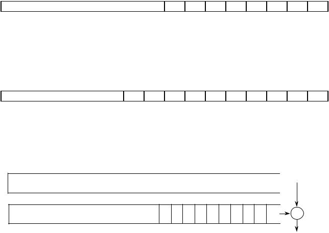
An exception vector is a memory location from which the processor fetches the address of a routine to handle an exception. Each exception type requires a handler routine and a unique vector. All exception vectors are two words in length (see Figure 6-1), except for the reset vector, which is four words long. All exception vectors reside in the supervisor data space, except for the reset vector, which is in the supervisor program space. A vector number is an 8-bit number that is multiplied by four to obtain the offset of an exception vector. Vector numbers are generated internally or externally, depending on the cause of the exception. For interrupts, during the interrupt acknowledge bus cycle, a peripheral provides an 8-bit vector number (see Figure 6-2) to the processor on data bus lines D7– D0.
The processor forms the vector offset by left-shifting the vector number two bit positions and zero-filling the upper-order bits to obtain a 32-bit long-word vector offset. In the MC68000, the MC68HC000, MC68HC001, MC68EC000, and the MC68008, this offset is used as the absolute address to obtain the exception vector itself, which is shown in Figure 6-3.
NOTE
In the MC68010, the vector offset is added to the 32-bit vector base register (VBR) to obtain the 32-bit absolute address of the exception vector (see Figure 6-4). Since the VBR is set to zero upon reset, the MC68010 functions identically to the
MC68000, MC68HC000, MC68HC001, MC68EC000, and MC68008 until the VBR is changed via the move control register MOVEC instruction.
|
EVEN BYTE (A0=0) |
EVEN BYTE (A0=0) |
|
|
|
|
|
WORD 0 |
NEW PROGRAM COUNTER (HIGH) |
A1=0 |
|
WORD 1 |
NEW PROGRAM COUNTER (LOW) |
A1=1 |
|
|
|
|
|
Figure 6-1. Exception Vector Format
6-4 |
M68000 8-/16-/32-BIT MICROPROCESSORS USER'S MANUAL |
MOTOROLA |

D15 |
D8 |
D7 |
|
|
|
|
|
|
D0 |
IGNORED |
|
v7 |
v6 |
v5 |
v4 |
v3 |
v2 |
v1 |
v0 |
Where:
v7 is the MSB of the vector number
v0 is the LSB of the vector number
Figure 6-2. Peripheral Vector Number Format
A31 |
A10 |
A9 |
A8 |
A7 |
A6 |
A5 |
A4 |
A3 |
A2 |
A1 |
A0 |
ALL ZEROES |
|
v7 |
v6 |
v5 |
v4 |
v3 |
v2 |
v1 |
v0 |
0 |
0 |
31
31
Figure 6-3. Address Translated from 8-Bit Vector Number (MC68000, MC68HC000, MC68HC001, MC68EC000, and MC68008)
|
|
|
0 |
|
|
CONTENTS OF VECTOR BASE REGISTER |
|
|
|
|
10 |
|
0 |
|
|
|
|
||
ALL ZEROES |
v7 v6 v5 v4 v3 v2 v1 v0 0 |
0 |
|
|
|
+ |
|||
|
|
|
|
|
EXCEPTION VECTOR
ADDRESS
Figure 6-4. Exception Vector Address Calculation (MC68010)
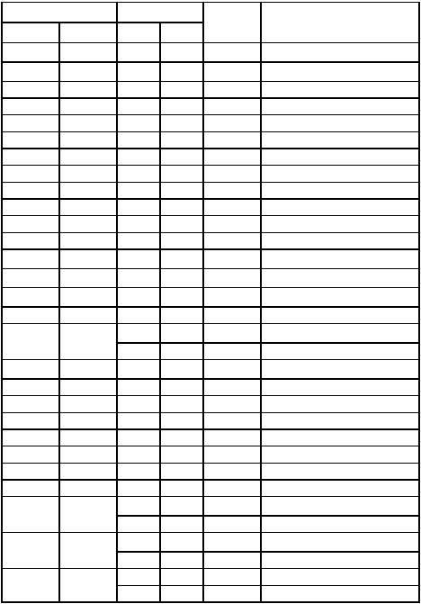
The actual address on the address bus is truncated to the number of address bits available on the bus of the particular implementation of the M68000 architecture. In all processors except the MC68008, this is 24 address bits. (A0 is implicitly encoded in the data strobes.) In the MC68008, the address is 20 or 22 bits in length. The memory map for exception vectors is shown in Table 6-2.
The vector table, Table 6-2, is 512 words long (1024 bytes), starting at address 0 (decimal) and proceeding through address 1023 (decimal). The vector table provides 255 unique vectors, some of which are reserved for trap and other system function vectors. Of the 255, 192 are reserved for user interrupt vectors. However, the first 64 entries are not protected, so user interrupt vectors may overlap at the discretion of the systems designer.
6.2.2 Kinds of Exceptions
Exceptions can be generated by either internal or external causes. The externally generated exceptions are the interrupts, the bus error, and reset. The interrupts are
MOTOROLA |
M68000 8-/16-/32-BIT MICROPROCESSORS USER’S MANUAL |
6-5 |
requests from peripheral devices for processor action; the bus error and reset inputs are used for access control and processor restart. The internal exceptions are generated by instructions, address errors, or tracing. The trap (TRAP), trap on overflow (TRAPV), check register against bounds (CHK), and divide (DIV) instructions can generate exceptions as part of their instruction execution. In addition, illegal instructions, word fetches from odd addresses, and privilege violations cause exceptions. Tracing is similar to a very high priority, internally generated interrupt following each instruction.
6-6 |
M68000 8-/16-/32-BIT MICROPROCESSORS USER'S MANUAL |
MOTOROLA |

Table 6-2. Exception Vector Assignment
Vectors Numbers |
Address |
|
|
||
Hex |
Decimal |
Dec |
Hex |
Space 6 |
Assignment |
0 |
0 |
0 |
000 |
SP |
Reset: Initial SSP2 |
1 |
1 |
4 |
004 |
SP |
Reset: Initial PC 2 |
2 |
2 |
8 |
008 |
SD |
Bus Error |
3 |
3 |
12 |
00C |
SD |
Address Error |
4 |
4 |
16 |
010 |
SD |
Illegal Instruction |
5 |
5 |
20 |
014 |
SD |
Zero Divide |
6 |
6 |
24 |
018 |
SD |
CHK Instruction |
7 |
7 |
28 |
01C |
SD |
TRAPV Instruction |
8 |
8 |
32 |
020 |
SD |
Privilege Violation |
9 |
9 |
36 |
024 |
SD |
Trace |
A |
10 |
40 |
028 |
SD |
Line 1010 Emulator |
B |
11 |
44 |
02C |
SD |
Line 1111 Emulator |
C |
121 |
48 |
030 |
SD |
(Unassigned, Reserved) |
D |
131 |
52 |
034 |
SD |
(Unassigned, Reserved) |
E |
14 |
56 |
038 |
SD |
Format Error 5 |
F |
15 |
60 |
03C |
SD |
Uninitialized Interrupt Vector |
10–17 |
16–231 |
64 |
040 |
SD |
(Unassigned, Reserved) |
|
|
92 |
05C |
|
— |
18 |
24 |
96 |
060 |
SD |
Spurious Interrupt3 |
19 |
25 |
100 |
064 |
SD |
Level 1 Interrupt Autovector |
1A |
26 |
104 |
068 |
SD |
Level 2 Interrupt Autovector |
1B |
27 |
108 |
06C |
SD |
Level 3 Interrupt Autovector |
1C |
28 |
112 |
070 |
SD |
Level 4 Interrupt Autovector |
1D |
29 |
116 |
074 |
SD |
Level 5 Interrupt Autovector |
1E |
30 |
120 |
078 |
SD |
Level 6 Interrupt Autovector |
1F |
31 |
124 |
07C |
SD |
Level 7 Interrupt Autovector |
20–2F |
32–47 |
128 |
080 |
SD |
TRAP Instruction Vectors4 |
|
|
188 |
0BC |
|
— |
30–3F |
48–631 |
192 |
0C0 |
SD |
(Unassigned, Reserved) |
|
|
255 |
0FF |
|
— |
40–FF |
64–255 |
256 |
100 |
SD |
User Interrupt Vectors |
|
|
1020 |
3FC |
|
— |
NOTES:
1.Vector numbers 12, 13, 16–23, and 48–63 are reserved for future enhancements by Motorola. No user peripheral devices should be assigned these numbers.
2.Reset vector (0) requires four words, unlike the other vectors which only require two words, and is located in the supervisor program space.
3.The spurious interrupt vector is taken when there is a bus error indication during interrupt processing.
4.TRAP #n uses vector number 32+ n.
5.MC68010 only. This vector is unassigned, reserved on the MC68000 and MC68008.
6.SP denotes supervisor program space, and SD denotes supervisor data space.
MOTOROLA |
M68000 8-/16-/32-BIT MICROPROCESSORS USER’S MANUAL |
6-7 |
