

6.2.3 Multiple Exceptions
These paragraphs describe the processing that occurs when multiple exceptions arise simultaneously. Exceptions can be grouped by their occurrence and priority. The group 0 exceptions are reset, bus error, and address error. These exceptions cause the instruction currently being executed to abort and the exception processing to commence within two clock cycles. The group 1 exceptions are trace and interrupt, privilege violations, and illegal instructions. Trace and interrupt exceptions allow the current instruction to execute to completion, but pre-empt the execution of the next instruction by forcing exception processing to occur. A privilege-violating instruction or an illegal instruction is detected when it is the next instruction to be executed. The group 2 exceptions occur as part of the normal processing of instructions. The TRAP, TRAPV, CHK, and zero divide exceptions are in this group. For these exceptions, the normal execution of an instruction may lead to exception processing.
Group 0 exceptions have highest priority, whereas group 2 exceptions have lowest priority. Within group 0, reset has highest priority, followed by address error and then bus error. Within group 1, trace has priority over external interrupts, which in turn takes priority over illegal instruction and privilege violation. Since only one instruction can be executed at a time, no priority relationship applies within group 2.
The priority relationship between two exceptions determines which is taken, or taken first, if the conditions for both arise simultaneously. Therefore, if a bus error occurs during a TRAP instruction, the bus error takes precedence, and the TRAP instruction processing is aborted. In another example, if an interrupt request occurs during the execution of an instruction while the T bit is asserted, the trace exception has priority and is processed first. Before instruction execution resumes, however, the interrupt exception is also processed, and instruction processing finally commences in the interrupt handler routine. A summary of exception grouping and priority is given in Table 6-3.
As a general rule, the lower the priority of an exception, the sooner the handler routine for that exception executes. For example, if simultaneous trap, trace, and interrupt exceptions are pending, the exception processing for the trap occurs first, followed immediately by exception processing for the trace and then for the interrupt. When the processor resumes normal instruction execution, it is in the interrupt handler, which returns to the trace handler, which returns to the trap execution handler. This rule does not apply to the reset exception; its handler is executed first even though it has the highest priority, because the reset operation clears all other exceptions.
6-8 |
M68000 8-/16-/32-BIT MICROPROCESSORS USER'S MANUAL |
MOTOROLA |
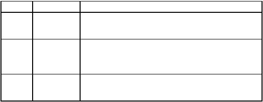
Table 6-3. Exception Grouping and Priority
Group |
Exception |
Processing |
0 |
Reset |
Exception Processing Begins within Two Clock Cycles |
|
Address Error |
|
|
Bus Error |
|
1 |
Trace |
Exception Processing Begins before the Next Instruction |
|
Interrupt |
|
|
Illegal |
|
|
Privilege |
|
2 |
TRAP, TRAPV, |
Exception Processing Is Started by Normal Instruction Execution |
|
CHK |
|
|
Zero Divide |
|
6.2.4 Exception Stack Frames
Exception processing saves the most volatile portion of the current processor context on the top of the supervisor stack. This context is organized in a format called the exception stack frame. Although this information varies with the particular processor and type of exception, it always includes the status register and program counter of the processor when the exception occurred.
The amount and type of information saved on the stack are determined by the processor type and exception type. Exceptions are grouped by type according to priority of the exception.
Of the group 0 exceptions, the reset exception does not stack any information. The information stacked by a bus error or address error exception in the MC68000, MC68HC000, MC68HC001, MC68EC000, or MC68008 is described in 6.3.9.1 Bus Error and shown in Figure 6-7.
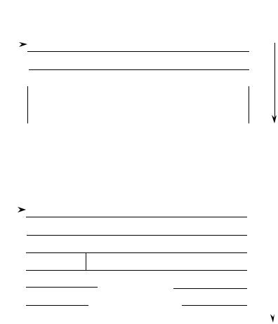
The MC68000, MC68HC000, MC68HC001, MC68EC000, and MC68008 group 1 and 2 exception stack frame is shown in Figure 6-5. Only the program counter and status register are saved. The program counter points to the next instruction to be executed after exception processing.
The MC68010 exception stack frame is shown in Figure 5-6. The number of words actually stacked depends on the exception type. Group 0 exceptions (except reset) stack
29 words and group 1 and 2 exceptions stack four words. To support generic exception handlers, the processor also places the vector offset in the exception stack frame. The format code field allows the return from exception (RTE) instruction to identify what information is on the stack so that it can be properly restored. Table 6-4 lists the MC68010 format codes. Although some formats are specific to a particular M68000 Family processor, the format 0000 is always legal and indicates that just the first four words of the frame are present.
MOTOROLA |
M68000 8-/16-/32-BIT MICROPROCESSORS USER’S MANUAL |
6-9 |
|
EVEN BYTE |
|
|
ODD BYTE |
|
7 |
0 |
7 |
0 |
|
|
15 |
|
|
0 |
HIGHER |
|
|
|
|
|
|
ADDRESS |
SSP |
|
STATUS REGISTER |
|
||
|
|
|
|||
|
PROGRAM COUNTER HIGH |
|
|
||
|
PROGRAM COUNTER LOW |
|
|
||
|
|
|
|
|
|
Figure 6-5. Group 1 and 2 Exception Stack Frame (MC68000, MC68HC000, MC68HC001, MC68EC000, and MC68008)
15 |
0 |
HIGHER |
|
|
|
|
ADDRESS |
SP |
|
STATUS REGISTER |
|
|
|
||
|
|
PROGRAM COUNTER HIGH |
|
|
|
PROGRAM COUNTER LOW |
|
|
FORMAT |
VECTOR OFFSET |
|
|
|
OTHER INFORMATION |
|
|
|
DEPENDING ON EXCEPTION |
|
|
|
|
|
Figure 6-6. MC68010 Stack Frame
6-10 |
M68000 8-/16-/32-BIT MICROPROCESSORS USER'S MANUAL |
MOTOROLA |