

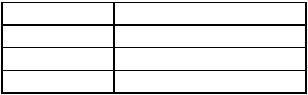
Table 6-4. MC68010 Format Codes
Format Code |
Stacked Information |
0000 |
Short Format (4 Words) |
1000 |
Long Format (29 Words) |
All Others |
Unassigned, Reserved |
6.2.5 Exception Processing Sequence
In the first step of exception processing, an internal copy is made of the status register.
After the copy is made, the S bit of the status register is set, putting the processor into the supervisor mode. Also, the T bit is cleared, which allows the exception handler to execute unhindered by tracing. For the reset and interrupt exceptions, the interrupt priority mask is also updated appropriately.
In the second step, the vector number of the exception is determined. For interrupts, the vector number is obtained by a processor bus cycle classified as an interrupt acknowledge cycle. For all other exceptions, internal logic provides the vector number. This vector number is then used to calculate the address of the exception vector.
The third step, except for the reset exception, is to save the current processor status. (The reset exception does not save the context and skips this step.) The current program counter value and the saved copy of the status register are stacked using the SSP. The stacked program counter value usually points to the next unexecuted instruction.
However, for bus error and address error, the value stacked for the program counter is unpredictable and may be incremented from the address of the instruction that caused the error. Group 1 and 2 exceptions use a short format exception stack frame (format = 0000 on the MC68010). Additional information defining the current context is stacked for the bus error and address error exceptions.
The last step is the same for all exceptions. The new program counter value is fetched from the exception vector. The processor then resumes instruction execution. The instruction at the address in the exception vector is fetched, and normal instruction decoding and execution is started.
6.3 PROCESSING OF SPECIFIC EXCEPTIONS
The exceptions are classified according to their sources, and each type is processed differently. The following paragraphs describe in detail the types of exceptions and the processing of each type.
6.3.1 Reset
The reset exception corresponds to the highest exception level. The processing of the reset exception is performed for system initiation and recovery from catastrophic failure.
Any processing in progress at the time of the reset is aborted and cannot be recovered. The processor is forced into the supervisor state, and the trace state is forced off. The
MOTOROLA |
M68000 8-/16-/32-BIT MICROPROCESSORS USER’S MANUAL |
6-11 |
interrupt priority mask is set at level 7. In the MC68010, the VBR is forced to zero. The vector number is internally generated to reference the reset exception vector at location 0 in the supervisor program space. Because no assumptions can be made about the validity of register contents, in particular the SSP, neither the program counter nor the status register is saved. The address in the first two words of the reset exception vector is fetched as the initial SSP, and the address in the last two words of the reset exception vector is fetched as the initial program counter. Finally, instruction execution is started at the address in the program counter. The initial program counter should point to the powerup/restart code.
The RESET instruction does not cause a reset exception; it asserts the RESET signal to reset external devices, which allows the software to reset the system to a known state and continue processing with the next instruction.
6.3.2 Interrupts
Seven levels of interrupt priorities are provided, numbered from 1–7. All seven levels are available except for the 48-pin version for the MC68008.
NOTE
The MC68008 48-pin version supports only three interrupt levels: 2, 5, and 7. Level 7 has the highest priority.
Devices can be chained externally within interrupt priority levels, allowing an unlimited number of peripheral devices to interrupt the processor. The status register contains a 3- bit mask indicating the current interrupt priority, and interrupts are inhibited for all priority levels less than or equal to the current priority.
An interrupt request is made to the processor by encoding the interrupt request levels 1–7 on the three interrupt request lines; all lines negated indicates no interrupt request. Interrupt requests arriving at the processor do not force immediate exception processing, but the requests are made pending. Pending interrupts are detected between instruction executions. If the priority of the pending interrupt is lower than or equal to the current processor priority, execution continues with the next instruction, and the interrupt exception processing is postponed until the priority of the pending interrupt becomes greater than the current processor priority.
If the priority of the pending interrupt is greater than the current processor priority, the exception processing sequence is started. A copy of the status register is saved; the privilege mode is set to supervisor mode; tracing is suppressed; and the processor priority level is set to the level of the interrupt being acknowledged. The processor fetches the vector number from the interrupting device by executing an interrupt acknowledge cycle, which displays the level number of the interrupt being acknowledged on the address bus.
If external logic requests an automatic vector, the processor internally generates a vector number corresponding to the interrupt level number. If external logic indicates a bus error, the interrupt is considered spurious, and the generated vector number references the spurious interrupt vector. The processor then proceeds with the usual exception processing, saving the format/offset word (MC68010 only), program counter, and status
6-12 |
M68000 8-/16-/32-BIT MICROPROCESSORS USER'S MANUAL |
MOTOROLA |
register on the supervisor stack. The offset value in the format/offset word on the
MC68010 is the vector number multiplied by four. The format is all zeros. The saved value of the program counter is the address of the instruction that would have been executed had the interrupt not been taken. The appropriate interrupt vector is fetched and loaded into the program counter, and normal instruction execution commences in the interrupt handling routine. Priority level 7 is a special case. Level 7 interrupts cannot be inhibited by the interrupt priority mask, thus providing a "nonmaskable interrupt" capability. An interrupt is generated each time the interrupt request level changes from some lower level to level 7. A level 7 interrupt may still be caused by the level comparison if the request level is a 7 and the processor priority is set to a lower level by an instruction.
6.3.3 Uninitialized Interrupt
An interrupting device provides an M68000 interrupt vector number and asserts data transfer acknowledge (DTACK), or asserts valid peripheral address (VPA), or auto vector
(AVEC), or bus error (BERR) during an interrupt acknowledge cycle by the MC68000. If the vector register has not been initialized, the responding M68000 Family peripheral provides vector number 15, the uninitialized interrupt vector. This response conforms to a uniform way to recover from a programming error.
6.3.4 Spurious Interrupt
During the interrupt acknowledge cycle, if no device responds by asserting DTACK or AVEC, VPA, BERR should be asserted to terminate the vector acquisition. The processor separates the processing of this error from bus error by forming a short format exception stack and fetching the spurious interrupt vector instead of the bus error vector. The processor then proceeds with the usual exception processing.
6.3.5 Instruction Traps
Traps are exceptions caused by instructions; they occur when a processor recognizes an abnormal condition during instruction execution or when an instruction is executed that normally traps during execution.
Exception processing for traps is straightforward. The status register is copied; the supervisor mode is entered; and tracing is turned off. The vector number is internally generated; for the TRAP instruction, part of the vector number comes from the instruction itself. The format/offset word (MC68010 only), the program counter, and the copy of the status register are saved on the supervisor stack. The offset value in the format/offset word on the MC68010 is the vector number multiplied by four. The saved value of the program counter is the address of the instruction following the instruction that generated the trap. Finally, instruction execution commences at the address in the exception vector.
Some instructions are used specifically to generate traps. The TRAP instruction always forces an exception and is useful for implementing system calls for user programs. The
TRAPV and CHK instructions force an exception if the user program detects a run-time error, which may be an arithmetic overflow or a subscript out of bounds.
MOTOROLA |
M68000 8-/16-/32-BIT MICROPROCESSORS USER’S MANUAL |
6-13 |
A signed divide (DIVS) or unsigned divide (DIVU) instruction forces an exception if a division operation is attempted with a divisor of zero.
6.3.6 Illegal and Unimplemented Instructions
Illegal instruction is the term used to refer to any of the word bit patterns that do not match the bit pattern of the first word of a legal M68000 instruction. If such an instruction is fetched, an illegal instruction exception occurs. Motorola reserves the right to define instructions using the opcodes of any of the illegal instructions. Three bit patterns always force an illegal instruction trap on all M68000-Family-compatible microprocessors. The patterns are: $4AFA, $4AFB, and $4AFC. Two of the patterns, $4AFA and $4AFB, are reserved for Motorola system products. The third pattern, $4AFC, is reserved for customer use (as the take illegal instruction trap (ILLEGAL) instruction).
NOTE
In addition to the previously defined illegal instruction opcodes, the MC68010 defines eight breakpoint (BKPT) instructions with the bit patterns $4848–$484F. These instructions cause the processor to enter illegal instruction exception processing as usual. However, a breakpoint acknowledge bus cycle, in which the function code lines (FC2–FC0) are high and the address lines are all low, is also executed before the stacking operations are performed. The processor does not accept or send any data during this cycle. Whether the breakpoint acknowledge cycle is terminated with a DTACK, BERR, or VPA signal, the processor continues with the illegal instruction processing. The purpose of this cycle is to provide a software breakpoint that signals to external hardware when it is executed.
Word patterns with bits 15–12 equaling 1010 or 1111 are distinguished as unimplemented instructions, and separate exception vectors are assigned to these patterns to permit efficient emulation. Opcodes beginning with bit patterns equaling 1111 (line F) are implemented in the MC68020 and beyond as coprocessor instructions. These separate vectors allow the operating system to emulate unimplemented instructions in software.
Exception processing for illegal instructions is similar to that for traps. After the instruction is fetched and decoding is attempted, the processor determines that execution of an illegal instruction is being attempted and starts exception processing. The exception stack frame for group 2 is then pushed on the supervisor stack, and the illegal instruction vector is fetched.
6-14 |
M68000 8-/16-/32-BIT MICROPROCESSORS USER'S MANUAL |
MOTOROLA |