


PROGRAMMABLE LOGIC DESIGN -- QUICK START HANDBOOK •
This design solution purely uses a microcontroller. The main functions it performs are:
•Interrupt control
•Status feedback to the PC
•Accurate motor control.
This configuration would probably be implemented in a single microcontroller device with specific motor control peripherals, such as a capture-com- pare unit.
This configuration would also need a built-in UART. These extra functions usually add extra cost to the overall microcontroller device.
Due to the nature of the microcontroller, the interrupt handling must be thoroughly mapped out, because interrupts could affect the speed of the motor.
In a safety-critical system, emergency stops implemented in software require exhaustive testing and verification before they can be used in the final system to ensure that they operate properly under all software related conditions, including software bugs and potential software states.
The output from the motor rotation sensor is very fast, so control of the speed of the motor could cause problems if system interrupts occurred.
DESIGN PARTITIONING
As we noted before, microcontrollers are very good at computational tasks, and CPLDs are excellent in high-speed systems, with their abundance of I/Os.
• 170
DESIGN REFERENCE BANK
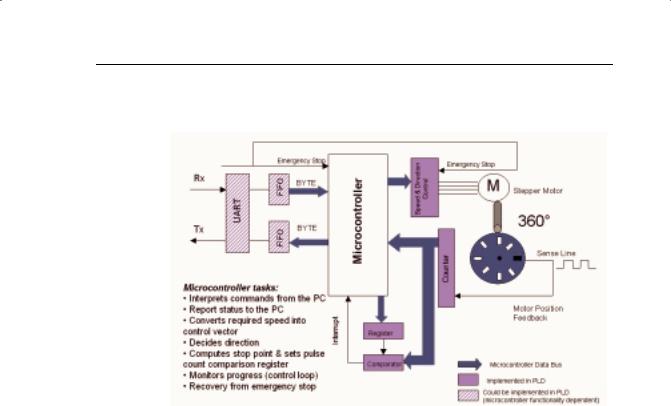
Figure 7-7 shows how we can use a microcontroller and a CPLD in a partitioned design to achieve the greatest control over a stepper motor.
FIGURE 7-7: PARTITIONED DESIGN: MICROCONTROLLER AND CPLD
The microcontroller:
•Interprets ASCII commands from the PC.
•Reports status of the motor to the PC.
•Converts required speed into control vectors (small mathematical algorithm).
•Decides direction of rotation of the motor.
•Computes stop point and sets a value into the pulse count comparison register.
•Monitors progress (control loop) and adapts speed.
•Recovers from emergency stops.
Although the microcontroller performs recovery from emergency stops, the actual emergency stop is implemented by the CPLD, because this is the safetycritical part of the design.
Because the CPLD is considered independent hardware, safety-critical proving and sign-off are more straightforward than software safety systems.
Additionally, all of the high-speed interface functions are also implemented in the CPLD, because it is very fast and has abundant inputs and outputs.
Meanwhile, the UART and FIFO sections of the design can be implemented in the microcontroller in the form of a microcontroller peripheral, or imple-
• 171

PROGRAMMABLE LOGIC DESIGN -- QUICK START HANDBOOK •
mented in a larger, more granular PLD such as an FPGA – for example, a Xilinx Spartan device.
Using a PLD in this design has the added benefit of gaining the ability to absorb any other discrete logic elements on the PCB or in the total design into the CPLD.
Under this new configuration, we can consider the CPLD as offering hard- ware-based subroutines or as a mini co-processor.
The microcontroller still performs ASCII string manipulation and mathematical functions, but it now has more time to perform these operations – without interruption. The motor control is now independently stable and safe.
Microcontroller/CPLD design partitioning can reduce overall system costs. This solution uses low-cost devices to implement the functions they do best – computational functions in the microcontroller and high-speed, high I/O tasks in the CPLD.
In safety-critical systems, why not put the safety-critical functions in “hardware” (CPLDs) to cut down on safety system approval time scales?
System testing can also be made easier by implementing the difficult-to- simulate interrupt handling into programmable logic.
Low-cost microcontrollers are now in the region of US $1.00, but if your design requires extra peripherals (for example, a capture-compare unit for accurate motor control, ADCs, or UARTs), this can quadruple the cost of your microcontroller.
A low cost microcontroller coupled with a low cost CPLD from Xilinx can deliver the same performance at approximately half the cost.
In low-power applications, microcontrollers are universally accepted as low-power devices and have been the automatic choice of designers.
The CoolRunner family of ultra-low power CPLDs are an ideal fit in this arena and may be used to complement your low-power microcontroller to integrate designs in battery-powered, portable designs (<100 A current consumption at standby).
CONCLUSION
Microcontrollers are ideally suited to computational tasks, whereas CPLDs are suited to very fast, I/O-intensive operations.
Partitioning your design across the two devices can increase overall system speeds, reduce costs, and potentially absorb all of the other discrete logic functions in a Design – thus presenting a truly reconfigurable system.
The design process for a microcontroller is very similar to that of a programmable logic device. This permits a shorter learning and designing cycle.
• 172