


DESIGN REFERENCE BANK
USING A MICROCONTROLLER TO CONTROL A STEPPER MOTOR
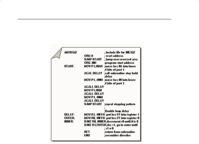
Figure 7-3 shows assembly language targeting a Philips 80C552 microcontroller.
The stepper motor that the microcontroller will control has four sets of coils. When logic level patterns are applied to each set of coils, the motor steps through its angles.
The speed of the stepper motor shaft depends on how fast the logic level patterns are applied to the four sets of coils. The manufacturer’s motor specification data sheet provides the stepping motor code.
A very common stepping code is given by the following hexadecimal numbers:
A |
9 |
5 |
6 |
Each hex digit is equal to four binary bits:
1010 1001 0101 0110
These binary bits represent voltage levels applied to each of the coil driver circuits. The steps are:
1010 |
5V |
0V |
5V |
0V |
1001 |
5V |
0V |
0V |
5V |
0101 |
0V |
5V |
0V |
5V |
0110 |
0V |
5V |
5V |
0V |
If you send this pattern repeatedly, then the motor shaft rotates.
• 165
PROGRAMMABLE LOGIC DESIGN -- QUICK START HANDBOOK •
The assembly language program in Figure 7-3 continually rotates the stepper motor shaft. By altering the value of R0 in the delay loop, this will give fine control over speed; altering the value of R1 will give coarse variations in speed.
FIGURE 7-3: ASSEMBLY LANGUAGE PROGRAM TO ROTATE THE STEPPER MOTOR SHAFT
STEPPER MOTOR CONTROL USING A CPLD
Figure 7-4 shows a design written in ABEL hardware description language.
Within the Xilinx CPLD, four inputs are required to fully control the stepper motor. The CLK input synchronizes the logic and determines the speed of rotation. The motor advances one step per clock period.
The angle of rotation of the shaft will depend on the specific motor used. The direction (DIR) control input changes the sequence at the outputs (PH1 to PH4) to reverse the motor direction.
The enable input (EN) determines whether the motor is rotating or holding. The active low reset input (RST) initializes the circuit to ensure that the correct starting sequence is provided to the outputs.
-- Stepper Motor Controller
library IEEE;
use IEEE.std_logic_1164.all;
entity step1 is
• 166

DESIGN REFERENCE BANK
port (
clk : in std_logic; -- input to determine speed of rotation rst : in std_logic; -- resets and initializes the circuit
en : in std_logic; -- determines whether motor rotating or holding dir : in std_logic; -- motor direction control
ph1 : inout std_logic; -- output to motor phase 1 ph2 : inout std_logic; -- output to motor phase 2 ph3 : inout std_logic; -- output to motor phase 3 ph4 : inout std_logic -- output to motor phase 4 );
end step1;
architecture equation of step1 is begin
Process (rst,clk) begin
if rst = '0' then ph1 <= '1';
ph2 <= '0'; ph3 <= '0'; ph4 <= '0';
else
if clk'event and clk='1' then
-- Stepper Motor Controller description equations
ph1 <= (not(dir)and en and not(ph1)and ph2 and not(ph3)and not(ph4))
or (dir and en and not(ph1)and not(ph2)and not(ph3)and ph4) or ( not(en)and ph1);
ph2 <= (not(dir)and en and not(ph1)and not(ph2)and ph3 and not(ph4))
or (dir and en and ph1 and not(ph2)and not(ph3)and not(ph4)) or (not(en)and ph2);
ph3 <= (not(dir)and en and not(ph1)and not(ph2) and not(ph3)and
ph4)
or (dir and en and not(ph1) and (ph2) and not(ph3)and not(ph4)) or (not(en)and ph3);
ph4 <= (not(dir)and en and ph1 and not(ph2) and not(ph3)and not(ph4))
or (dir and en and not(ph1) and not(ph2)and ph3 and not(ph4)) or (not(en) and ph4);
end if; end if;
end process; end equation;
• 167

PROGRAMMABLE LOGIC DESIGN -- QUICK START HANDBOOK •
FIGURE 7-4: CPLD ABEL PROGRAM TO CONTROL A STEPPER MOTOR
The phase equations (PH1 to PH4) are written with a colon and equal sign (:=) to indicate a registered implementation of the combinatorial equation.
Each phase equation is either enabled (EN), indicating that the motor is rotating, or disabled (!EN), indicating that the current active phase remains on and the motor is locked.
The value of the direction input (DIR) determines which product term is used to sequence clockwise or counterclockwise. The asynchronous equations (for example, ph1.AR=!rst) initialize the circuit.
The ABEL hardware description motor control module can be embedded within a macro function and saved as a reusable standard logic block, which can be shared by many designers within the same organization – this is the beauty of design reuse.
This “hardware” macro function is independent of any other function or event not related to its operation. Therefore, it cannot be affected by extraneous system interrupts or other unconnected system state changes.
Such independence is critical in safety systems. Extraneous system interrupts in a purely software-based system could cause indeterminate states that are hard to test or simulate.
PC-BASED MOTOR CONTROL
Our next example (Figure 7-5 and Figure 7-6) is more complex, because now the motor is connected to a PC-based system via an RS-232 serial connection.
This implementation has a closed loop system controlling rotation, speed, and direction.
There is also the addition of a safety-critical emergency stop, which has the highest level of system interrupt. This means that if the emergency stop is acti-
• 168
DESIGN REFERENCE BANK
vated, it will override any other process or interrupt and will immediately stop the motor from rotating.
FIGURE 7-5: DESIGN PARTITIONING
FIGURE 7-6: MICROCONTROLLER IMPLEMENTATION
• 169