

PROGRAMMABLE LOGIC DESIGN -- QUICK START HANDBOOK • CHAPTER 4
Top-Level VHDL Designs
At this point in the flow, two modules in the design are connected together by a top-level file.
Some designers like to create a top-level schematic diagram, while others like to keep the design entirely text-based.
Because this section discusses the latter, the counter and state machine will be connected using a top.vhd file.
If you prefer the former, jump directly to the next section Top-Level Schematic Designs, page 125. You will have the opportunity to do both by continuing through this tutorial.
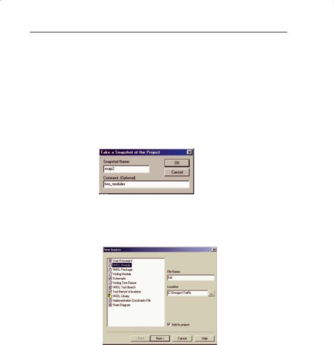
Take a snapshot of the project from Project > Take Snapshot.
FIGURE 4-24: PROJECT SNAPSHOT
From the Project menu, select New Source and create a VHDL module called “top.”
FIGURE 4-25: NEW SOURCE WINDOW SHOWING VHDL MODULE
Xilinx • 120
WEBPACK ISE DESIGN ENTRY
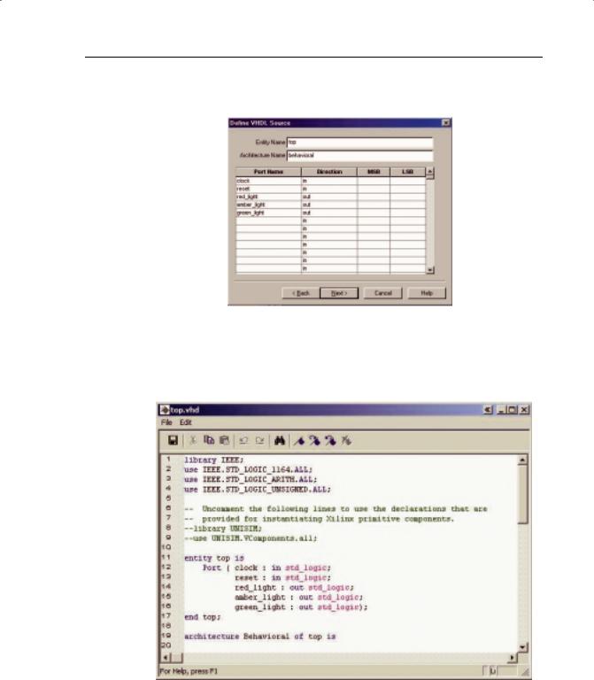
Click on the Next> button and fill out the Define VHDL Source dialog box, as shown in Figure 4-26.
FIGURE 4-26: DEFINE VHDL SOURCE WINDOW
Click on the Next> button, then the Finish button.
Your new file, “top.vhd,” should look like Figure 4-27.
FIGURE 4-27: NEW VHDL FILE
Xilinx • 121
PROGRAMMABLE LOGIC DESIGN -- QUICK START HANDBOOK • CHAPTER 4
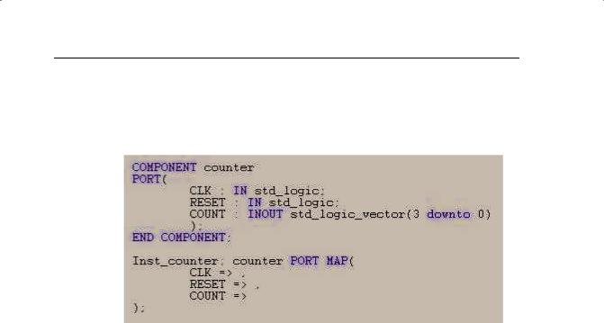
In the Sources window, highlight “counter.vhd.”
In the Process window, double-click View VHDL Instantiation Template from the Design Entry Utilities section.
Highlight and copy the component declaration and instantiation.
FIGURE 4-28: INSTANTIATION TEMPLATE
Close the instantiation template, as shown in Figure 4-28.
Paste the component declaration and instantiation into “top.vhd.”
Rearrange the component declaration so that it lies before the begin statement in the architecture. Rearrange the instantiation so that it lies between the begin and end statement (see Figure 4-29 for reference).
Highlight “stat_mac.vhd” in the Sources window and double-click View VHDL Instantiation Template from the Design Utilities section.
Repeat the copy-and-paste procedure previously described.
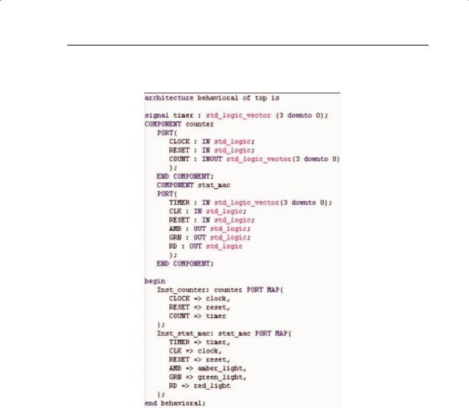
Declare a signal called “timer” by adding the following line above the component declarations inside the architecture:
signal timer : std_logic_vector(3 downto 0);
Xilinx • 122
WEBPACK ISE DESIGN ENTRY
Connect the counter and state machine instantiated modules so that your “top.vhd” file looks like Figure 4-29.
FIGURE 4-29: TOP.VHD FILE
When you save “top.vhd,” notice how the Sources window automatically manages the hierarchy of the whole design, with “counter.vhd” and “stat_mac.vhd” becoming sub-modules of “top.vhd.”
You can now simulate the entire design.
Add a new testbench waveform source as before, but this time, associate it with the module “top.”
Accept the timing in the Initialize Timing dialog box and click OK.
In the waveform diagram, enter the input stimulus as follows:
Set the RESET cell below CLK cycle 1 to a value of “1.”
Xilinx • 123
PROGRAMMABLE LOGIC DESIGN -- QUICK START HANDBOOK • CHAPTER 4
Click the RESET cell below CLK cycle 2 to reset if low.
Scroll to the 64th clock cycle; right-click and select Set End of
Testbench.
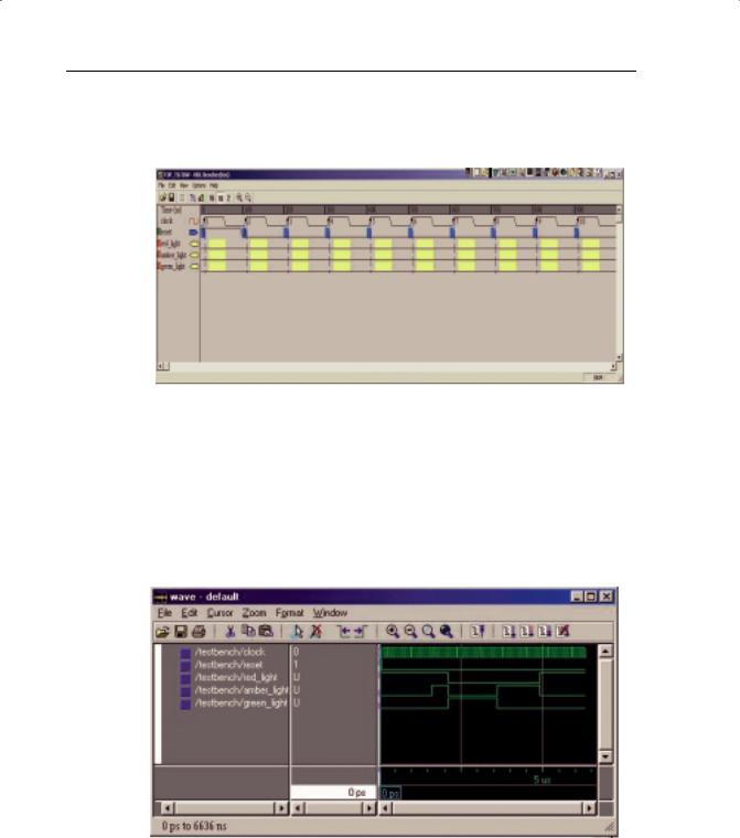
FIGURE 4-30: Waveform Diagram
Close the Edit Test Bench window.
Click the Save Waveform button.
Close the HDL Bencher tool.
The “top_tb.tbw” file will now be associated with the top-level VHDL mod-
ule.
Simulate Functional VHDL Model in the Process window.
FIGURE 4-31: WAVEFORM WINDOW
Xilinx • 124