

PROGRAMMABLE LOGIC DESIGN -- QUICK START HANDBOOK • CHAPTER 4
You can remove the source files from the WebPACK ISE GUI by clicking on the add/remove arrow.
As the project builds, you will notice how the WebPACK ISE tool manages hierarchy and associated files in the Sources window.
Double-clicking on any file name in the Sources window allows that file to be edited in the main Text Editor.
THE LANGUAGE TEMPLATE
The language template is an excellent tool to assist you in creating HDL code.
It has a range of popular functions such as counters, multiplexers, decoders, and shift registers. It also has templates for creating common operators (such as “IF/THEN” and “FOR” loops) often associated with software languages.
Language templates are used as a reference. They can be copied and pasted into the design, then customized for their intended purpose.
Usually, you must change the bus width or signal names, and sometimes modify the functionality.
In this tutorial, the template uses the signal name “clk.” The design requires the signal to be called “clock.” The counter in the template is too complex for this particular requirement, so some sections are deleted.
Open the language templates by clicking the button located on the far right side of the toolbar.
You can also access the language template from the Edit > Language Template menu.
Click and drag the counter template from the VHDL > Synthesis > Templates folder and drop it into the “counter.vhd” architecture between the begin and end statements.
An alternate method is to highlight the code in the language template that you want to use in your code and right-click your mouse button. Then select use in “counter.vhd.”
CLOSE THE LANGUAGE TEMPLATES
Notice the color-coding used in the HDL Editor. The green text indicates a comment. The commented text in this template shows which libraries are required in the VHDL header. The port definitions are required if this counter was used in its entirety.
Xilinx • 104

WEBPACK ISE DESIGN ENTRY
As you have already created the entity, this information is not required. You can delete the green comments if you wish.
The counter from the template shows a loadable bidirectional counter. For this design, only a 4-bit up counter is required.
EDIT THE COUNTER MODULE
Replace “clk” with the word “clock” by using the Edit > Replace function.
Delete this section:
if CE='1' then
if LOAD='1' then COUNT <= DIN;
else
if DIR='1' then
Delete this section:
else
COUNT <= COUNT - 1; end if;
end if; end if;
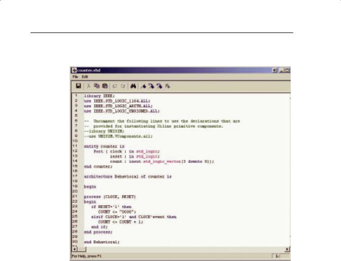
The counter module should now look like Figure 4-7.
For the purposes of debugging code, several new features are available in the Source Editor window.
A right-click in the gray bar on the left side of the Source Editor window will bring up a menu of these features.
Xilinx • 105
PROGRAMMABLE LOGIC DESIGN -- QUICK START HANDBOOK • CHAPTER 4
You can toggle the line numbers in the side bar on or off and place bookmarks to mark lines of interest in the source file.
FIGURE 4-7: COUNTER IN VHDL WINDOW
A typical VHDL module consists of library declarations, an entity, and an architecture.
The library declarations are needed to tell the compiler which packages are required.
The entity declares all ports associated with the design. Count (3 down to 0) means that count is a 4-bit logic vector.
This design has two inputs – clock and reset – and one output, a 4-bit bus called “count.”
The actual functional description of the design appears after the begin statement in the architecture.
The function of this design is to increment a signal “count” when clock = 1 and there is an event on the clock. This is resolved into a positive edge.
The reset is asynchronous as is evaluated before the clock action.
Xilinx • 106