

PROGRAMMABLE LOGIC DESIGN -- QUICK START HANDBOOK • CHAPTER 4
If the design had only one module (one level of hierarchy), the implementation phase would be the next step.
This design, however, has a further module to represent a more typical VHDL design.
State Machine Editor
For our traffic light design, the counter acts as a timer that determines the transitions of a state machine.
The state machine will run through four states, each state controlling a combination of the three lights.
State 1: Red Light
State 2: Red and Amber Light
State 3: Green Light
State 4: Amber Light
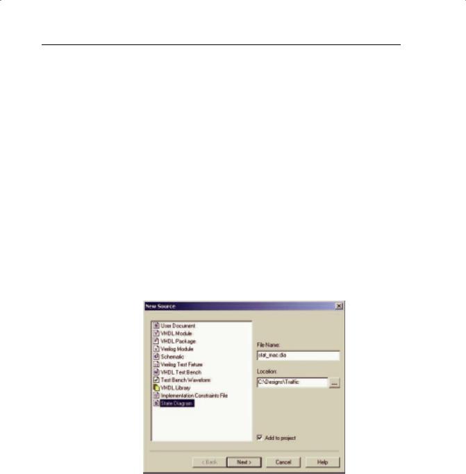
To invoke the state machine editor, select New Source from the project menu.
Highlight State Diagram and give it the name “stat_mac.dia.”
Click the Next> button, then the Finish button.
FIGURE 4-15: NEW SOURCE WINDOW
Xilinx • 112
WEBPACK ISE DESIGN ENTRY
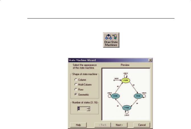
Open the State Machine Wizard by clicking on the button in the main toolbar.
FIGURE 4-16: STATE MACHINE WIZARD WINDOW
Set the number of states to “4” and hit the Next> button. Click the Next> button to build a synchronous state machine.
Xilinx • 113
PROGRAMMABLE LOGIC DESIGN -- QUICK START HANDBOOK • CHAPTER 4
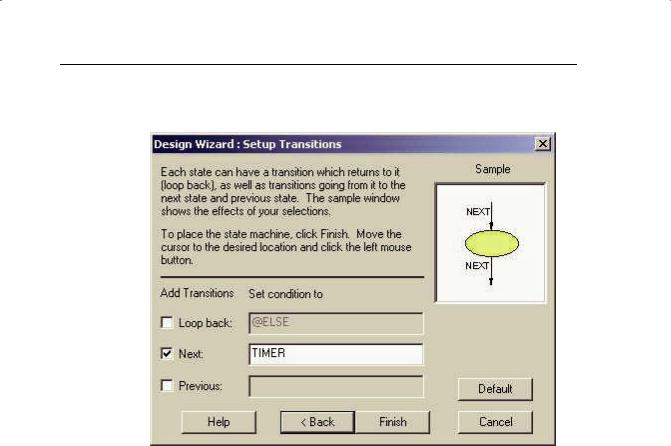
In the Setup Transitions box, type “TIMER” in the Next field (shown in Figure 4-17).
FIGURE 4-17: SETUP TRANSITIONS WINDOW
Click on the Finish button and drop the state machine on the page.
Double-click on the Reset State 0 colored yellow. Rename the state name “RED.”
Hit the Output Wizard button.
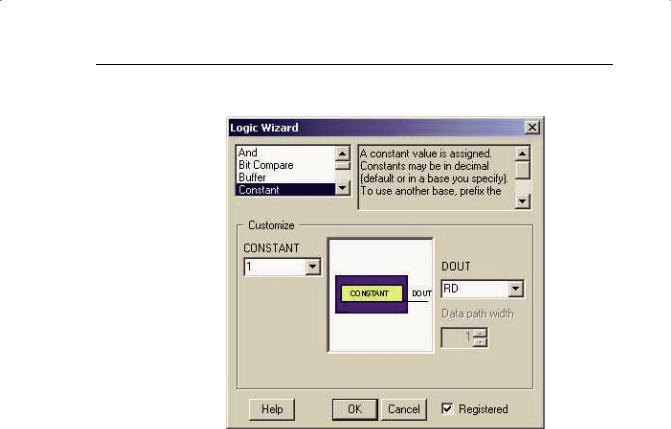
This design will have three outputs named RD, AMB, and GRN. In the DOUT field, type “RD” to declare an output.
Xilinx • 114
WEBPACK ISE DESIGN ENTRY
Set RD to a constant “1” with a registered output, as shown in Figure 4-18.
FIGURE 4-18: LOGIC WIZARD WINDOW
Click on OK and then OK the Edit State box.
In a similar fashion, edit the other states:
Rename State 1 to “REDAMB” and use the output wizard to set RD = 1, and a new output AMB equal to “1” with a registered output.
Rename State 2 to “GREEN” and use the output wizard to set a new output GRN equal to “1” with a registered output.
Rename State 3 to “AMBER” and use the output wizard to set AMB = 1.
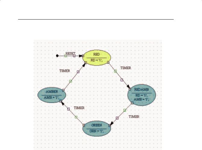
The state machine should look like Figure 4-19.
Xilinx • 115
PROGRAMMABLE LOGIC DESIGN -- QUICK START HANDBOOK • CHAPTER 4
(If you set a signal as registered in the Output Wizard and then select Signal and re-open the wizard, it is no longer ticked as registered.)
FIGURE 4-19: STATE DIAGRAM
Double-click on the transition line between state “RED” and state “REDAMB.”
Xilinx • 116
WEBPACK ISE DESIGN ENTRY
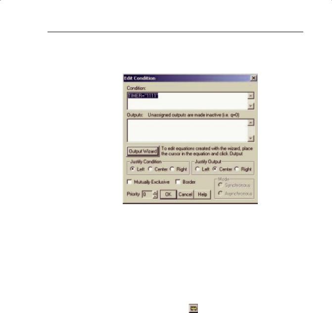
In the edit condition window, set a transition to occur when timer is 1111 by editing the Condition field to TIMER = “1111.” (Don’t forget the double quotes (“), as these are part of VHDL syntax.).
FIGURE 4-20: EDIT CONDITIONS WINDOW
Repeat for the other transitions:
Transition REDAMB to GREEN, TIMER = “0100”
Transition GREEN to AMBER, TIMER = “0011”
Transition AMBER to RED, TIMER = “0000”
Hence, the traffic light completes a RED, REDAMB, GREEN, AMBER once every three cycles of the counter.
Finally, declare the vector TIMER by clicking on the button on the left-hand side of the toolbar.
Xilinx • 117
PROGRAMMABLE LOGIC DESIGN -- QUICK START HANDBOOK • CHAPTER 4
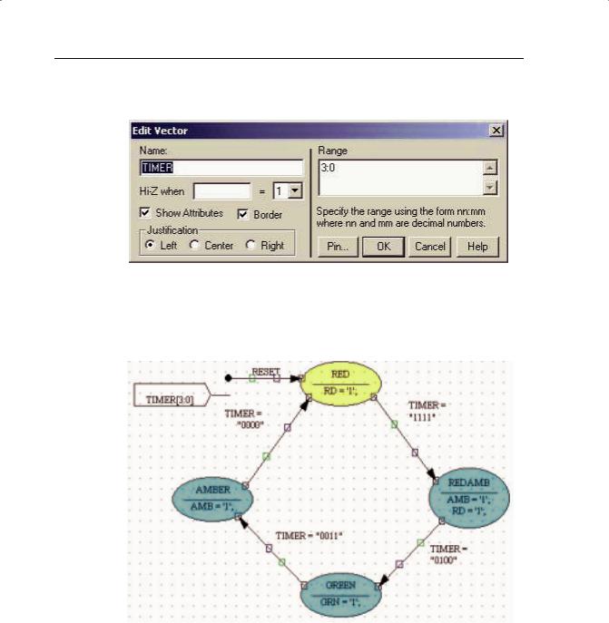
Drop the marker on the page, double-click on it, and enter the name “TIMER” with a width of 4 bits (Range 3:0).
FIGURE 4-21: EDIT VECTOR WINDOW
Click OK.
Your completed state machine should look like Figure 4-22.
FIGURE 4-22: STATE MACHINE DRAWING
Xilinx • 118
WEBPACK ISE DESIGN ENTRY
Click on the Generate HDL button on the top toolbar.
The Results window should read “Compiled Perfectly.” Close the dialog box and the generated HDL Browser window.
Save and close StateCAD.
The state machine can now be added to the WebPACK ISE project.
In the Project Navigator, go to the Project menu and select Add Source. In the Add Existing Sources box, find “STAT_MAC.vhd.”
Click on Open and declare it as a VHDL Module.
In the Project Navigator, go to the Project menu and select Add Source. In the Add Existing Sources box, find “stat_mac.dia.”
The state diagram will be added to the top of the Sources window. Doubleclicking on this file will open up the state diagram in StateCAD.
FIGURE 4-23: SOURCE IN PROJECT WINDOW SHOWING MODEL VIEW
Xilinx • 119