

Network Plus 2005 In Depth
.pdf252 Chapter 6 TOPOLOGIES AND ACCESS METHODS
Backbone Networks
A network backbone is the cabling that connects the hubs, switches, and routers on a network. Backbones usually are capable of more throughput than the cabling that connects workstations to hubs. This added capacity is necessary because backbones carry more traffic than any other cabling in the network. For example, LANs in large organizations commonly rely on a fiberoptic backbone but continue to use CAT 5 or better UTP to connect hubs or switches with workstations.
Although even the smallest LAN technically has a backbone, on an enterprise-wide network, backbones are more complex and more difficult to plan. In networking, the term enterprise refers to an entire organization, including its local and remote offices, a mixture of computer systems, and a number of departments. Enterprise-wide computing must therefore take into account the breadth and diversity of a large organization’s computer needs. The backbone is the most significant building block of enterprise-wide networks. It may take one of several different shapes, as described in the following sections.
Serial Backbone
A serial backbone is the simplest kind of backbone. It consists of two or more internetworking devices connected to each other by a single cable in a daisy-chain fashion. In networking, a daisy chain is simply a linked series of devices. Hubs and switches are often connected in a daisy chain to extend a network. For example, suppose you manage a small star-wired bus topology network in which a single hub serves a workgroup of eight users. When new employees are added to that department and you need more network connections, you could connect a second hub to the first hub in a daisy-chain fashion. The new hub would offer open ports for new users. Because the star-wired hybrids provide for modular additions, daisy chaining is a logical solution for growth. Also, because hubs can easily be connected through cables attached to their ports, a LAN’s infrastructure can be expanded with little additional cost.
Hubs are not the only devices that can be connected in a serial backbone. Gateways, routers, switches, and bridges can also form part of the backbone. Figure 6-6 illustrates a serial backbone network, in which the backbone is indicated by a dashed line.
The extent to which you can connect hubs in a serial backbone is limited. For example, in a 10BASE-T network, you may use a maximum of four hubs to connect five network segments in a serial fashion. Using more hubs than the standard suggests (in other words, exceeding the maximum network length) will adversely affect the functionality of a LAN. On a 100BASETX network, you may use a maximum of two hubs connecting three network segments. And on most 1-Gbps networks, you can use only one hub to extend the network. If you extend a LAN beyond its recommended size, intermittent and unpredictable data transmission errors will result. Similarly, if you daisy-chain a topology with limited bandwidth, you risk overloading the channel and generating still more data errors.

BACKBONE NETWORKS |
Chapter 6 253 |
FIGURE 6-6 A serial backbone
Distributed Backbone
A distributed backbone consists of a number of connectivity devices connected to a series of central connectivity devices, such as hubs, switches, or routers, in a hierarchy, as shown in Figure 6-7. In Figure 6-7, the dashed lines represent the backbone. This kind of topology allows for simple expansion and limited capital outlay for growth, because more layers of devices can be added to existing layers. For example, suppose that you are the network administrator for a small publisher’s office. You might begin your network with a distributed backbone consisting
FIGURE 6-7 A simple distributed backbone

254 Chapter 6 TOPOLOGIES AND ACCESS METHODS
of two switches that supply connectivity to your 20 users, 10 on each switch. When your company hires more staff, you can connect another switch to one of the existing switches, and use the new switch to connect the new staff to the network.
A more complicated distributed backbone connects multiple LANs or LAN segments using routers, as shown in Figure 6-8. In this example, the routers form the highest layer of the backbone to connect the LANs or LAN segments.
FIGURE 6-8 A distributed backbone connecting multiple LANs
A distributed backbone also provides network administrators with the ability to segregate workgroups and therefore manage them more easily. It adapts well to an enterprise-wide network confined to a single building, in which certain hubs or switches can be assigned according to the floor or department. Note that distributed backbones may include hubs linked in a daisychain fashion. This arrangement requires the same length considerations that serial backbones demand. Another possible problem in this design relates to the potential single points of failure, such as the devices at the uppermost layers. Despite these potential drawbacks, implementing a distributed backbone network can be relatively simple, quick, and inexpensive.
Collapsed Backbone
The collapsed backbone topology uses a router or switch as the single central connection point for multiple subnetworks, as shown in Figure 6-9. Contrast Figure 6-9 with Figure 6-8, in which multiple LANs are connected via a distributed backbone. In a collapsed backbone, a single router or switch is the highest layer of the backbone. The router or switch that makes

BACKBONE NETWORKS |
Chapter 6 255 |
FIGURE 6-9 A collapsed backbone
up the collapsed backbone must contain multiprocessors to handle the heavy traffic going through it. This is risky because a failure in the central router or switch can bring down the entire network. In addition, because routers cannot move traffic as quickly as hubs, using a router may slow data transmission.
Nevertheless, a collapsed backbone topology offers substantial advantages. Most significantly, this arrangement allows you to interconnect different types of subnetworks. You can also centrally manage maintenance and troubleshooting chores.
Parallel Backbone
A parallel backbone is the most robust type of network backbone. This variation of the collapsed backbone arrangement consists of more than one connection from the central router or switch to each network segment. In a network with more than one router or switch, the parallel backbone calls for duplicate connections between those connectivity devices as well. Figure 6-10 depicts a simple parallel backbone topology. As you can see, each hub is connected to the router or switch by two cables, and the two routers are also connected by two cables. The most significant advantage of using a parallel backbone is that its redundant (duplicate) links ensure network connectivity to any area of the enterprise. Parallel backbones are more expensive than other enterprise-wide topologies because they require much more cabling than the others. However, they make up for the additional cost by offering increased performance and better fault tolerance.

256 Chapter 6 TOPOLOGIES AND ACCESS METHODS
FIGURE 6-10 A parallel backbone
As a network administrator, you might choose to implement parallel connections to only some of the most critical devices on your network. For example, if the first and second hubs in Figure 6-10 connected your Facilities and Payroll Departments to the rest of the network, and your organization could never afford to lose connectivity with those departments, you might use a parallel structure for those links. If the third and fourth hubs in Figure 6-10 connected your organization’s Recreation and Training Departments to the network, you might decide that parallel connections were unnecessary for these departments. By selectively implementing the parallel structure, you can lower connectivity costs and leave available additional ports on the connectivity devices.
Bear in mind that an enterprise-wide LAN or WAN may include different combinations of simple physical topologies and backbone designs. Now that you understand fundamental physical topologies and backbone networks, you are ready to understand the related concept of logical topologies.
Logical Topologies
NET+ |
The term logical topology refers to the way in which data is transmitted between nodes, rather |
1.1than the physical layout of the paths that data takes. A network’s logical topology will not necessarily match its physical topology.
The most common logical topologies are bus and ring. In a bus logical topology, signals travel from one network device to all other devices on the network (or network segment). They may

SWITCHING |
Chapter 6 257 |
NET+ |
or may not travel through an intervening connectivity device (as in a star topology network). |
1.1A network that uses a bus physical topology also uses a bus logical topology. In addition, networks that use either the star or star-wired bus physical topologies also result in a bus logical topology.
In contrast, in a ring logical topology, signals follow a circular path between sender and receiver. Networks that use a pure ring topology use a ring logical topology. The ring logical topology is also used by the star-wired ring hybrid physical topology because signals follow a circular path, even as they travel through a connectivity device (as shown by the dashed lines in Figure 6-4). Different types of networks are characterized by one of the two main logical topologies. For example, Ethernet networks use the bus logical topology, whereas Token Ring networks use the ring logical topology.
Understanding logical topologies is useful when troubleshooting and designing networks. For example, on Ethernet networks, it is necessary to understand that all of a segment’s traffic is transmitted to all nodes in the manner of a bus logical topology. Thus, for example, if one device has a malfunctioning NIC that is issuing bad or excessive packets, those packets will be detected by the NICs of all devices on the same segment. The result is a waste of available bandwidth and potential transmission errors. When network engineers casually refer to topologies, however, they are most often referring to a network’s physical topology.
Switching
NET+ |
Switching is a component of a network’s logical topology that determines how connections |
2.14are created between nodes. There are three methods for switching: circuit switching, message switching, and packet switching.
Circuit Switching
In circuit switching, a connection is established between two network nodes before they begin transmitting data. Bandwidth is dedicated to this connection and remains available until the users terminate communication between the two nodes. While the nodes remain connected, all data follows the same path initially selected by the switch. When you place a telephone call, for example, your call typically uses a circuit-switched connection.
Because circuit switching monopolizes its piece of bandwidth while the two stations remain connected (even when no actual communication is taking place), it can result in a waste of available resources. However, some network applications benefit from such a “reserved” path. For example, live audio or videoconferencing might not tolerate the time delay it would take to reorganize data packets that have taken separate paths through another switching method. Another example of circuit switching occurs when you connect your home PC via modem to your Internet service provider’s access server. WAN technologies, such as ISDN and T1 service, also use circuit switching, as does ATM, a technology discussed later in this chapter.

258 Chapter 6 TOPOLOGIES AND ACCESS METHODS
Message Switching
Message switching establishes a connection between two devices, transfers the information to the second device, and then breaks the connection. The information is stored and forwarded from the second device after a connection between that device and a third device on the path is established. This “store and forward” routine continues until the message reaches its destination. All information follows the same physical path; unlike with circuit switching, however, the connection is not continuously maintained. Message switching requires that each device in the data’s path has sufficient memory and processing power to accept and store the information before passing it to the next node. None of the network transmission technologies discussed in this chapter use message switching.
NET+ Packet Switching
2.14A third and by far the most popular method for connecting nodes on a network is packet switching. Packet switching breaks data into packets before they are transported. Packets can travel any path on the network to their destination, because each packet contains the destination address and sequencing information. Consequently, packets can attempt to find the fastest circuit available at any instant. They need not follow each other along the same path, nor must they arrive at their destination in the same sequence as when they left their source.
To understand this technology, imagine that you work in Washington, D.C. and you organized a field trip for 50 colleagues to the National Air and Space Museum. You gave the museum’s exact address to your colleagues and told them to leave precisely at 7:00 A.M. from your office building several blocks away. You did not tell your coworkers which route to take. Some might choose the subway, others might hail a taxicab, and still others might choose to drive their own cars or even walk. All of them will attempt to find the fastest route to the museum. But if a group of six decide to take a taxicab and only four people fit in that taxi, the next two people have to wait for a taxi. Or a taxi might get caught in rush hour traffic and be forced to find an alternate route. Thus, the fastest route might not be obvious the moment everyone departs. But no matter which transportation method your colleagues choose, all will arrive at the museum and reassemble as a group. This analogy illustrates how packets travel in a packet-switched network.
When packets reach their destination node, the node reassembles them based on their control information. Because of the time it takes to reassemble the packets into a message, packet switching is not optimal for live audio or video transmission. Nevertheless, it is a fast and efficient mechanism for transporting typical network data, such as e-mail messages, spreadsheet files, or even software programs from a server to client. The greatest advantage to packet switching lies in the fact that it does not waste bandwidth by holding a connection open until a message reaches its destination, as circuit switching does. And unlike message switching, it does not require devices in the data’s path to process any information. Ethernet networks and the Internet are the most common examples of packet-switched networks.
Now that you are familiar with the various types of switching, you are ready to investigate specific network technologies that may use switching.

ETHERNET |
Chapter 6 259 |
Ethernet
NET+ |
As you have learned, Ethernet is a network technology originally developed by Xerox in the |
1.21970s and later improved by Digital Equipment Corporation (DEC), Intel, and Xerox (“DIX”). This flexible technology can run on a variety of network media and offers excellent throughput at a reasonable cost. Ethernet is, by far, the most popular network technology used on modern LANs.
Ethernet has evolved through many variations, and continues to improve. As a result of this history, it supports many different versions—so many, in fact, that you will probably find the many variations a little confusing. However, all Ethernet networks have at least one thing in common—their access method, which is known as CSMA/CD.
CSMA/CD (Carrier Sense Multiple Access with
Collision Detection)
A network’s access method is its method of controlling how network nodes access the communications channel. In comparing a network to a highway, the on-ramps would be one part of the highway’s access method. A busy highway might use stoplights at each on-ramp to allow only one person to merge into traffic every five seconds. After merging, cars are restricted to lanes and each lane is limited as to how many cars it can hold at one time. All of these highway controls are designed to avoid collisions and help drivers get to their destinations. On networks, similar restrictions apply to the way in which multiple computers share a finite amount of bandwidth on a network. These controls make up the network’s access method.
The access method used in Ethernet is called CSMA/CD (Carrier Sense Multiple Access with Collision Detection). All Ethernet networks, independent of their speed or frame type, rely on CSMA/CD. To understand Ethernet, you must first understand CSMA/CD. Take a minute to think about the full name “Carrier Sense Multiple Access with Collision Detection.” The term “Carrier Sense” refers to the fact that Ethernet NICs listen on the network and wait until they detect (or sense) that no other nodes are transmitting data over the signal (or carrier) on the communications channel before they begin to transmit. The term “Multiple Access” refers to the fact that several Ethernet nodes can be connected to a network and can monitor traffic, or access the media, simultaneously.
In CSMA/CD, when a node wants to transmit data it must first access the transmission media and determine whether the channel is free. If the channel is not free, it waits and checks again after a very brief amount of time. If the channel is free, the node transmits its data. Any node can transmit data after it determines that the channel is free. But what if two nodes simultaneously check the channel, determine that it’s free, and begin to transmit? When this happens, their two transmissions interfere with each other; this is known as a collision.
The last part of the term CSMA/CD, “collision detection,” refers to the way nodes respond to a collision. In the event of a collision, the network performs a series of steps known as the collision detection routine. If a node’s NIC determines that its data has been involved in a collision, it immediately stops transmitting. Next, in a process called jamming, the NIC issues a
260 |
|
|
Chapter 6 TOPOLOGIES AND ACCESS METHODS |
|
|
||||
|
|
|
|
|
|
|
special 32-bit sequence that indicates to the rest of the network nodes that its previous trans- |
||
NET+ |
|
|
||
1.2mission was faulty and that those data frames are invalid. After waiting, the NIC determines if the line is again available; if it is available, the NIC retransmits its data.
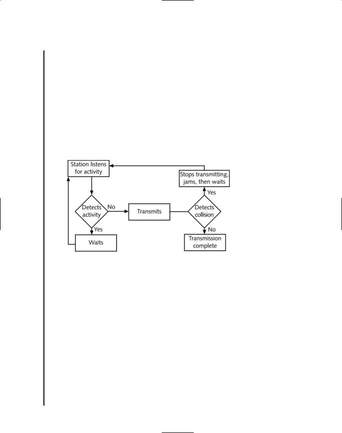
On heavily trafficked networks, collisions are fairly common. It is not surprising that the more nodes there are transmitting data on a network, the more collisions that will take place. (Although a collision rate greater than 5% of all traffic is unusual and may point to a problematic NIC or poor cabling on the network.) When an Ethernet network grows to include a particularly large number of nodes, you may see performance suffer as a result of collisions. This “critical mass” number depends on the type and volume of data that the network regularly transmits. Collisions can corrupt data or truncate data frames, so it is important that the network detect and compensate for them. Figure 6-11 depicts the way CSMA/CD regulates data flow to avoid and, if necessary, detect collisions.
FIGURE 6-11 CSMA/CD process
On an Ethernet network, a collision domain is the portion of a network in which collisions occur if two nodes transmit data at the same time. When designing an Ethernet network, it’s important to note that because repeaters simply regenerate any signal they receive, they repeat collisions just as they repeat data. Thus, connecting multiple parts of a network with repeaters results in a larger collision domain. Higher-layer connectivity devices, such as switches and routers, however, can separate collision domains.
Collision domains play a role in the Ethernet cabling distance limitations. For example, if there is more than 100 meters distance between two nodes on a segment connected to the same 100BASE-TX network bus, data propagation delays will be too long for CSMA/CD to be effective. A data propagation delay is the length of time data takes to travel from one point on the segment to another point. When data takes a long time, CSMA/CD’s collision detection routine cannot identify collisions accurately. In other words, one node on the segment might begin its CSMA/CD routine and determine that the channel is free even though a second node has begun transmitting, because the second node’s data is taking so long to reach the first node.

ETHERNET |
Chapter 6 261 |
NET+ |
At rates of 100 or 1000 Mbps, data travels so quickly that NICs can’t always keep up with the |
1.2collision detection and retransmission routines. For example, because of the speed employed on a 100BASE-TX network, the window of time for the NIC to both detect and compensate for the error is much less than that of a 10BASE-T network. To minimize undetected collisions, 100BASE-TX networks can support only a maximum of three network segments connected with two hubs, whereas 10BaseT buses can support a maximum of five network segments connected with four hubs. This shorter path reduces the highest potential propagation delay between nodes.
NET+ Switched Ethernet
1.2Traditional Ethernet LANs, called shared Ethernet, supply a fixed amount of bandwidth that
2.14must be shared by all devices on a segment, and all nodes on that segment belong to the same collision domain. Stations cannot send and receive data simultaneously, nor can they transmit a signal when another station on the same segment is sending or receiving data. This is because they share a segment and a hub or repeater, which merely amplifies and retransmits a signal over the segment. In contrast, a switch can separate a network segment into smaller segments, with each segment being independent of the others and supporting its own traffic. Switched Ethernet enables multiple nodes to simultaneously transmit and receive data over different logical network segments. By doing so, each node can individually take advantage of more bandwidth. Figure 6-12 shows how switches can isolate network segments.
Using switched Ethernet increases the effective bandwidth of a network segment because fewer workstations must vie for the same time on the wire. For organizations with existing 10BASE- T infrastructure, switches offer a relatively simple and inexpensive way to augment each node’s available bandwidth. Switches can be placed strategically on an organization’s network to balance
FIGURE 6-12 A switched Ethernet network