


398 Appendix B: Case Study and Sample Configuration
What’s Wrong with This Picture?
Now that you have successfully gone through the configuration scenarios in the previous sections, this section focuses on problem solving after or during an implementation of the Cisco PIX Firewall. Examples B-9 through B-11 show the configuration of three PIX firewalls for this exercise.
Example B-9 Atlanta PIX Firewall Configuration
1.: Saved
2.:
3.PIX Version 6.2(2)
4.nameif ethernet0 outside security0
5.nameif ethernet1 inside security100
6.nameif ethernet2 DMZ security70
7.enable password ksjfglkasglc encrypted
8.passwd kjngczftglkacytiur encrypted
9.hostname Atlanta
10.domain-name www.BranchVPN.com
11.fixup protocol ftp 21
12.fixup protocol http 80
13.fixup protocol smtp 25
14.fixup protocol skinny 2000
15.names
16.access-list inbound permit icmp any host 192.168.3.10
17.access-list inbound permit tcp any host 192.168.3.10 eq www
18.access-list inbound permit tcp any host 192.168.3.10 eq 443
19.access-list DMZ permit udp 172.16.3.0 255.255.255.0 host 10.10.3.240 eq ntp
20.access-list VPN permit ip 10.10.3.0 255.255.255.0 10.10.2.0 255.255.255.0
21.access-list VPN permit ip 10.10.3.0 255.255.255.0 10.10.10.0 255.255.255.0
22.access-list LosAngeles permit ip 10.10.3.0 255.255.255.0 10.10.10.0 255.255.255.0
23.access-list Boston permit ip 10.10.3.0 255.255.255.0 10.10.2.0 255.255.255.0
24.pager lines 24
25.logging on
26.logging timestamp
27.interface ethernet0 auto
28.interface ethernet1 auto
29.interface ethernet2 auto
30.mtu outside 1500
31.mtu inside 1500
32.ip address outside 192.168.3.1 255.255.255.0
33.ip address inside 10.10.3.1 255.255.255.0
34.ip address DMZ 172.16.3.1 255.255.255.0
35.arp timeout 14400
36.global (outside) 1 192.168.3.20-200
37.nat (inside) 1 0.0.0.0 0.0.0.0 0 0
38.nat (inside) 0 access-list VPN
39.static (DMZ,outside) 192.168.3.10 172.16.3.10 netmask 255.255.255.255 0 0
40.access-group inbound in interface outside
41.access-group DMZ in interface DMZ
42.route outside 0.0.0.0 0.0.0.0 192.168.3.254 1
43.timeout xlate 3:00:00


400 Appendix B: Case Study and Sample Configuration
Example B-10 Boston PIX Firewall Configuration (Continued)
17.access-list inbound permit tcp any host 192.168.2.10 eq www
18.access-list inbound permit tcp any host 192.168.2.10 eq 443
access-list DMZ permit tcp 192.168.1.13 255.255.255.255 192.168.2.11 eq 1521
19.access-list DMZ permit udp 172.16.2.0 255.255.255.0 host 10.10.2.240 eq ntp
20.access-list VPN permit ip 10.10.2.0 255.255.255.0 10.10.10.0 255.255.255.0
21.access-list VPN permit ip 10.10.2.0 255.255.255.0 10.10.3.0 255.255.255.0
22.access-list LosAngeles permit ip 10.10.2.0 255.255.255.0 10.10.10.0 255.255.255.0
23.access-list Atlanta permit ip 10.10.2.0 255.255.255.0 10.10.3.0 255.255.255.0
24.pager lines 24
25.logging on
26.logging timestamp
27.interface ethernet0 auto
28.interface ethernet1 auto
29.interface ethernet2 auto
30.mtu outside 1500
31.mtu inside 1500
32.ip address outside 192.168.2.1 255.255.255.0
33.ip address inside 10.10.2.1 255.255.255.0
34.ip address DMZ 172.16.2.1 255.255.255.0
35.arp timeout 14400
36.global (outside) 1 192.168.2.20-200
37.nat (inside) 1 0.0.0.0 0.0.0.0 0 0
38.nat (inside) 0 access-list VPN
39.static (DMZ,outside) 192.168.2.10 172.16.2.10 netmask 255.255.255.255 0 0 static (DMZ,outside) 192.168.2.11 172.16.2.11 netmask 255.255.255.255 0 0
40.access-group inbound in interface outside
41.access-group DMZ in interface DMZ
42.route outside 0.0.0.0 0.0.0.0 192.168.2.254 1
43.timeout xlate 3:00:00
44.timeout conn 1:00:00 half-closed 0:10:00 udp 0:02:00
45.timeout uauth 0:05:00 absolute
46.aaa-server TACACS+ protocol tacacs+
47.aaa-server RADIUS protocol radius
48.no snmp-server location
49.no snmp-server contact
50.snmp-server community public
51.no snmp-server enable traps
52.floodguard enable
53.sysopt connection permit-ipsec
54.crypto ipsec transform-set BranchVPN esp-3des esp-md5-hmac
55.crypto ipsec transform-set NothingNew esp-3des esp-sha-hmac
56.crypto map BranchVPN 10 ipsec-isakmp
57.crypto map BranchVPN 10 match address LosAngeles
58.crypto map BranchVPN 10 set peer 192.168.1.1
59.crypto map BranchVPN 10 set transform-set BranchVPN
60.crypto map BranchVPN 20 ipsec-isakmp
61.crypto map BranchVPN 20 match address Atlanta
62.crypto map BranchVPN 20 set peer 192.168.3.1
63.crypto map BranchVPN 20 set transform-set BranchVPN
64.crypto map BranchVPN interface outside
65.isakmp enable outside

402 Appendix B: Case Study and Sample Configuration
Example B-11 Los Angeles PIX Firewall Configuration
36.logging timestamp
37.interface ethernet0 auto
38.interface ethernet1 auto
39.interface ethernet2 auto
40.mtu outside 1500
41.mtu inside 1500
42.ip address outside 192.168.1.1 255.255.255.0
43.ip address inside 10.10.10.1 255.255.255.0
44.ip address DMZ 172.16.1.1 255.255.255.0
45.failover
46.failover timeout 0:00:00
47.failover poll 15
48.failover ip address outside 192.168.1.2
49.failover ip address inside 10.10.10.2
50.failover ip address DMZ 172.16.1.2
51.arp timeout 14400
52.global (outside) 1 192.168.1.20-250
53.nat (inside) 1 0.0.0.0 0.0.0.0 0 0
54.nat (inside) 0 access-list VPN
55.static (DMZ,outside) 192.168.1.10 172.16.1.10 netmask 255.255.255.255 0 0
56.static (DMZ,outside) 192.168.1.11 172.16.1.11 netmask 255.255.255.255 0 0
57.static (DMZ,outside) 192.168.1.12 172.16.1.12 netmask 255.255.255.255 0 0
58.static (DMZ,outside) 192.168.1.13 172.16.1.13 netmask 255.255.255.255 0 0 static (DMZ,outside) 192.168.1.14 172.16.1.14 netmask 255.255.255.255 0 0
59.access-group inbound in interface outside access-group Exchange in interface outside
60.access-group DMZ in interface DMZ
61.route outside 0.0.0.0 0.0.0.0 192.168.1.254 1
62.timeout xlate 3:00:00
63.timeout conn 1:00:00 half-closed 0:10:00 udp 0:02:00 rpc 0:10:00 h323 0:05:00 sip 0:30:00 sip_media 0:02:00
64.timeout uauth 0:05:00 absolute
65.aaa-server TACACS+ protocol tacacs+
66.aaa-server RADIUS protocol radius
67.no snmp-server location
68.no snmp-server contact
69.snmp-server community public
70.no snmp-server enable traps
71.floodguard enable
72.sysopt connection permit-ipsec
73.no sysopt route dnat
74.crypto ipsec transform-set BranchVPN esp-3des esp-md5-hmac
75.crypto ipsec transform-set NothingNew esp-3des esp-sha-hmac
76.crypto map BranchVPN 10 ipsec-isakmp
77.crypto map BranchVPN 10 match address Boston
78.crypto map BranchVPN 10 set peer 192.168.2.1
79.crypto map BranchVPN 10 set transform-set BranchVPN
80.crypto map BranchVPN 20 ipsec-isakmp
81.crypto map BranchVPN 20 match address Atlanta
82.crypto map BranchVPN 20 set peer 192.168.3.1
83.crypto map BranchVPN 20 set transform-set BranchVPN
84.crypto map BranchVPN interface outside

What’s Wrong with This Picture? 403
Example B-11 Los Angeles PIX Firewall Configuration
85.isakmp enable outside
86.isakmp key ******** address 192.168.2.1 netmask 255.255.255.255
87.isakmp key ******** address 192.168.3.1 netmask 255.255.255.255
88.isakmp identity address
89.isakmp policy 20 authentication pre-share
90.isakmp policy 20 encryption 3des
91.isakmp policy 20 hash md5
92.isakmp policy 20 group 2
93.isakmp policy 20 lifetime 86400
94.terminal width 80
95.Cryptochecksum:e0clmj3546549637cbsFds54132d5
After you have reviewed the configuration files for the three PIX firewalls, answer the following questions (the answers appear in Appendix A):
1The VPN session is established, but no traffic, or just one-way traffic, is passing between the firewalls. Ellen starts enabled logging and starts a debug icmp trace. She pings the other end of the VPN node and gets the following results:
LOCAL_PIX(config)# 609001: Built local-host inside:192.168.4.1
106014: Deny inbound icmp src outside:192.168.2.6 dst inside:192.168.4.1 (type 8, code 0)
106014: Deny inbound icmp src outside:192.168.2.6 dst inside:192.168.4.1 (type 8, code 0)
106014: Deny inbound icmp src outside:192.168.2.6 dst inside:192.168.4.1 (type 8, code 0)
106014: Deny inbound icmp src outside:192.168.2.6 dst inside:192.168.4.1 (type 8, code 0)
106014: Deny inbound icmp src outside:192.168.2.6 dst inside:192.168.4.1 (type 8, code 0)
609002: Teardown local-host inside:192.168.4.1 duration 0:00:15
What do these results indicate and what could be causing this problem? How would you help Ellen resolve this issue?
2Eric cannot get the VPN tunnel to work from HQ to the Philadelphia branch office. He starts a debug and gets the following results:
crypto_isakmp_process_block: src 172.16.172.40, dest 172.16.172.34 VPN Peer: ISAKMP: Added new peer: ip:172.16.172.40 Total VPN Peers:1 VPN Peer: ISAKMP: Peer ip:172.16.172.40 Ref cnt incremented to:1
Total VPN Peers:1
OAK_MM exchange
ISAKMP (0): processing SA payload. message ID = 0
ISAKMP (0): Checking ISAKMP transform 1 against priority 10 policy
ISAKMP: encryption DES-CBC

404 Appendix B: Case Study and Sample Configuration
ISAKMP: |
hash MD5 |
|
ISAKMP: |
default group 1 |
|
ISAKMP: |
auth pre-share |
|
ISAKMP: |
life type in seconds |
|
ISAKMP: |
life duration (basic) of 2400 |
|
ISAKMP |
(0): atts are acceptable. Next payload is 0 |
|
ISAKMP |
(0): SA is doing pre-shared key authentication using id type |
|
ID_IPV4 |
|
|
_ADDR |
|
|
return |
status is IKMP_NO_ERROR |
|
crypto_isakmp_process_block: src 172.16.172.40, dest 172.16.172.34 OAK_MM exchange
ISAKMP (0): processing KE payload. message ID = 0
ISAKMP (0): processing NONCE payload. message ID = 0
ISAKMP (0): processing vendor id payload
ISAKMP (0): processing vendor id payload
ISAKMP (0): remote peer supports dead peer detection
ISAKMP (0): processing vendor id payload
ISAKMP (0): speaking to another IOS box!
return status is IKMP_NO_ERROR
crypto_isakmp_process_block: src 172.16.172.40, dest 172.16.172.34
OAK_MM exchange |
|
|
ISAKMP (0): processing |
ID payload. message ID = 0 |
|
ISAKMP (0): processing |
HASH payload. message ID = 0 |
|
ISAKMP (0): SA has been authenticated |
||
ISAKMP (0): ID payload |
|
|
next-payload : |
8 |
|
type |
: |
1 |
protocol |
: |
17 |
port |
: |
500 |
length |
: |
8 |
ISAKMP (0): Total payload length: 12 |
||
return status is IKMP_NO_ERROR |
||
crypto_isakmp_process_block: src 172.16.172.40, dest 172.16.172.34 |
||
ISAKMP (0): processing |
NOTIFY payload 24578 protocol 1 |
|
spi 0, message |
ID = 2457631438 |
|
ISAKMP (0): processing |
notify INITIAL_CONTACTIPSEC(key_engine): got a |
|
queue |
|
|
event... |
|
|
IPSEC(key_engine_delete_sas): |
rec’d delete notify from ISAKMP |
IPSEC(key_engine_delete_sas): |
delete all SAs shared with 172.16.172.40 |

What’s Wrong with This Picture? 405
return status is IKMP_NO_ERR_NO_TRANS
crypto_isakmp_process_block: src 172.16.172.40, dest 172.16.172.34 OAK_QM exchange
oakley_process_quick_mode: OAK_QM_IDLE
ISAKMP (0): processing SA payload. message ID = 133935992
ISAKMP : Checking IPSec proposal 1
ISAKMP: transform 1, ESP_DES
ISAKMP: |
attributes |
in transform: |
|
ISAKMP: |
encaps is 1 |
|
|
ISAKMP: |
SA life |
type in seconds |
|
ISAKMP: |
SA life |
duration |
(basic) of 28800 |
ISAKMP: |
SA life |
type in kilobytes |
|
ISAKMP: |
SA life |
duration |
(VPI) of 0x0 0x46 0x50 0x0 |
ISAKMP: |
authenticator is |
HMAC-MD5 |
|
IPSEC(validate_proposal): invalid local address 172.16.172.34 ISAKMP (0): atts not acceptable. Next payload is 0
ISAKMP (0): SA not acceptable!
ISAKMP (0): sending NOTIFY message 14 protocol 0 return status is IKMP_ERR_NO_RETRANS
crypto_isakmp_process_block: src 172.16.172.40, dest 172.16.172.34 ISAKMP (0:0): phase 2 packet is a duplicate of a previous packet.
What could be the cause of this problem?
3Bruce is having problems establishing a VPN session to the Seattle office. He gets the following debug results:
IPSEC(crypto_map_check): crypto map mymap 10 incomplete. No peer or
access-list specified. Packet discarded
What is causing this problem, and how would you help Bruce successfully establish a VPN tunnel to the Seattle office?
4The web administrator in Los Angeles needs to maintain the web servers in the DMZ from the internal network using terminal services (TCP Port 3389). Is the firewall in Los Angeles configured to allow this access? Explain your answer.
5The web administrator in Los Angeles also needs to administer the web servers in Boston and Atlanta. Are the three firewalls configured to allow this access? Explain your answer.
6The web server 172.16.1.13 needs to access an Oracle database server that sits on a segment connected to the internal network at 10.10.11.221. The web server initiates the connection on TCP port 1521 and retrieves inventory data. Can this connection be completed? Explain your answer.


G L O S S A R Y
A
access list. A list kept by routers to control access to or from the router for a number of services (for example, to prevent packets with a certain IP address from leaving a particular interface on the router or firewall).
acknowledgment (ACK). A notification sent from one network device to another to acknowledge that an event occurred (such as the receipt of a message). See also negative acknowledgment (NAK).
ActiveX. Microsoft's Windows-specific non-Java technique for writing applets. ActiveX applets take considerably longer to download than the equivalent Java applets; however, they more fully exploit the features of Windows 95. ActiveX sometimes is said to be a superset of Java. See also applet and Java.
address resolution. Generally, a method of resolving differences between computer addressing schemes. Address resolution usually specifies a method of mapping network layer (Layer 3) addresses to data link layer (Layer 2) addresses.
aggressive mode. The connection mode that eliminates several steps during IKE authentication negotiation (phase 1) between two or more IPSec peers. Aggressive mode is faster than main mode but not as secure.
AH. Authentication Header. A security protocol that provides data authentication and optional antireplay services. AH is embedded in the data to be protected (a full IP datagram).
algorithm. A well-defined rule or process for arriving at a solution to a problem. In networking, algorithms commonly are used to determine the best route for traffic from a particular source to a particular destination.
antireplay. A security service in which the receiver can reject old or duplicate packets to protect itself against replay attacks. IPSec provides this optional service by use of a sequence number combined with the use of data authentication. PIX Firewall IPSec provides this service whenever it provides the data authentication service, except when the service is unavailable for manually established security associations (that is, security associations established by manual configuration and not by IKE).
applet. A small program, often used in the context of a Java-based program, that is compiled and embedded in an HTML page. See also ActiveX and Java.

410 application layer
application layer. Layer 7 of the OSI reference model. This layer provides services to application processes (such as e-mail, file transfer, and terminal emulation) that are outside the OSI reference model. The application layer identifies and establishes the availability of intended communication partners (and the resources required to connect with them), synchronizes cooperating applications, and establishes agreement on the procedures for error recovery and control of data integrity. See also data link layer, network layer, physical layer, presentation layer, session layer, and transport layer.
authentication. In security, verifying the identity of a person or process.
B
bit. A binary digit used in the binary numbering system. Can be 0 or 1.
C
certificate. A digital representation of user or device attributes, including a public key, that is signed with an authoritative private key.
certification authority (CA). Responsible for managing digital certificate requests and issuing digital certificates to participating IPSec network peers. These services provide centralized key management for the participating peers.
Cisco IOS Software. Cisco system software that provides common functionality, scalability, and security for all products under the CiscoFusion architecture. Cisco IOS allows centralized, integrated, automated installation and management of internetworks while ensuring support for a wide variety of protocols, media, services, and platforms.
console. DTE through which commands are entered into a host.
cryptographic algorithm. An algorithm that employs the science of cryptography, including encryption algorithms, cryptographic hash algorithms, digital signature algorithms, and key agreement algorithms.
cryptographic key. Usually shortened to just “key.” An input parameter that varies the transformation performed by a cryptographic algorithm.
Diffie-Hellman key exchange 411
D
Data Encryption Standard (DES). A standard cryptographic algorithm developed by the U.S. National Bureau of Standards.
data flow. A grouping of traffic, identified by a combination of source address/ mask, destination address/mask, IP next protocol field, and source and destination ports, in which the protocol and port fields can have the values of any. In effect, all traffic matching a specific combination of these values is grouped logically into a data flow. A data flow can represent a single TCP connection between two hosts, or it can represent all the traffic between two subnets. IPSec protection is applied to data flows.
data link layer. Layer 2 of the OSI reference model. Provides reliable transit of data across a physical link. The data link layer is concerned with physical addressing, network topology, line discipline, error notification, ordered delivery of frames, and flow control. The IEEE divides this layer into two sublayers: the MAC sublayer and the LLC sublayer. Sometimes this is simply called the link layer. See also application layer, network layer, physical layer, presentation layer, session layer, and transport layer.
decrypt. Cryptographically restores ciphertext to the plaintext form it had before encryption.
decryption. Reverse application of an encryption algorithm to encrypted data, thereby restoring that data to its original, unencrypted state. See also encryption.
default route. A routing table entry that is used to direct frames for which a next hop is not explicitly listed in the routing table.
Diffie-Hellman algorithm. Introduced by Whitfield Diffie and Martin Hellman in 1976, this was the first system to use public keys, or asymmetric cryptographic keys. Today Diffie-Hellman is part of the IPSec standard. A protocol known as Oakley uses Diffie-Hellman, as described in RFC 2412. Oakley is used by the Internet Key Exchange (IKE) protocol (see RFC 2401), which is part of the overall framework called Internet Security Association and Key Management Protocol (ISAKMP; see RFC 2408).
Diffie-Hellman key exchange. A public key cryptography protocol that allows two parties to establish a shared secret over insecure communications channels. Diffie-Hellman is used within Internet Key Exchange (IKE) to establish session keys. Diffie-Hellman is a component of Oakley key exchange. Cisco IOS Software supports 768-bit and 1024-bit Diffie-Hellman groups.

412 digital certificate
digital certificate. A certificate document in the form of a digital data object (a data object used by a computer) to which is appended a computed digital signature value that depends on the data object.
digital signature. A value computed with a cryptographic algorithm and appended to a data object in such a way that any recipient of the data can use the signature to verify the data's origin and integrity.
DNS. Domain Name System. A system used on the Internet to translate names of network nodes into addresses.
dynamic address resolution. Using an address resolution protocol to determine and store address information on demand.
E
e-mail. Electronic mail. A widely used network application in which text messages are transmitted electronically between end users over various types of networks using various network protocols.
encapsulation. Wrapping data in a particular protocol header. For example, Ethernet data is wrapped in a specific Ethernet header before network transit. Also, when bridging dissimilar networks, the entire frame from one network is simply placed in the header used by the other network's data link layer protocol. See also tunneling.
encryption. Applying a specific algorithm to data to alter its appearance, making it incomprehensible to those who are not authorized to see the information. See also decryption.
end-to-end encryption. Continuous protection of data that flows between two points in a network. This is accomplished by encrypting data when it leaves its source, leaving it encrypted while it passes through any intermediate computers (such as routers), and decrypting it only when it arrives at its intended destination.
enterprise network. A large and diverse network connecting most major points in a company or other organization. It differs from a WAN in that it is privately owned and maintained.
ESP. Encapsulating Security Payload. A security protocol that provides data privacy services, optional data authentication, and antireplay services. ESP encapsulates the data to be protected.

GUI 413
Ethernet. A baseband LAN specification invented by Xerox Corporation and developed jointly by Xerox, Intel, and Digital Equipment Corporation. Ethernet networks use CSMA/CD and run over a variety of cable types at 10 Mbps. Ethernet is similar to the IEEE 802.3 series of standards.
F
Fast Ethernet. Any of a number of 100-Mbps Ethernet specifications. Fast Ethernet offers a speed increase that is ten times that of the 10BASE-T Ethernet specification while preserving such qualities as frame format, MAC mechanisms, and MTU. Such similarities allow the use of existing 10BASE-T applications and network management tools on Fast Ethernet networks. Based on an extension to the IEEE 802.3 specification.
firewall. A router or access server, or several routers or access servers, designated as a buffer between any connected public networks and a private network. A firewall router uses access lists and other methods to ensure the security of the private network.
flow. A stream of data traveling between two endpoints across a network (for example, from one LAN station to another). Multiple flows can be transmitted on a single circuit.
G
Gb. Gigabit. Approximately 1,000,000,000 bits.
Gbps. Gigabits per second.
Gigabit Ethernet. A standard for high-speed Ethernet approved by the IEEE (Institute of Electrical and Electronic Engineers) 802.3z standards committee in 1996.
GUI. Graphical user interface. A user environment that uses pictorial as well as textual representations of applications' input and output and the hierarchical or other data structure in which information is stored. Such conventions as buttons, icons, and windows are typical, and many actions are performed using a pointing device, such as a mouse. Microsoft Windows and the Apple Macintosh are prominent examples of platforms that use a GUI.

414 H.323
H
H.323. Allows dissimilar communication devices to communicate with each other using a standardized communication protocol. H.323 defines a common set of codecs, call setup and negotiating procedures, and basic data transport methods.
hijack attack. A form of active wiretapping in which the attacker seizes control of a previously established communication association.
HMAC. Hash-based Message Authentication Code. A mechanism for message authentication that uses cryptographic hash functions. HMAC can be used with any iterative cryptographic hash function, such as MD5 or SHA-1, in combination with a secret shared key. HMAC's cryptographic strength depends on the properties of the underlying hash function.
HMAC-MD5. Hashed Message Authentication Codes with MD5 (see RFC 2104). A keyed version of MD5 that lets two parties validate transmitted information using a shared secret.
HTML. Hypertext Markup Language. A simple hypertext document formatting language that uses tags to indicate how a given part of a document should be interpreted by a viewing application, such as a web browser.
HTTP. Hypertext Transfer Protocol. The protocol used by web browsers and web servers to transfer files, such as text and graphic files.
I
ICMP. Internet Control Message Protocol. A network layer Internet protocol that reports errors and provides other information relevant to IP packet processing. See RFC 792.
IKE. Internet Key Exchange. Establishes a shared security policy and authenticates keys for services that require keys, such as IPSec. Before any IPSec traffic can be passed, each router/firewall/host must verify its peer's identity. This can be done by manually entering preshared keys into both hosts or by using a CA service.
Internet. The largest global internetwork. It connects tens of thousands of networks worldwide and has a “culture” that focuses on research and standardization based on real-life use. Many leading-edge network technologies come from the Internet community. The Internet evolved in part from ARPANET. The Internet used to be called the DARPA Internet. Do not confuse it with the general term internet.

ISAKMP 415
intrusion detection. A security service that monitors and analyzes system events for the purpose of finding (and providing real-time or near-real-time warnings about) unauthorized attempts to access system resources.
IP. Internet Protocol. A network layer protocol in the TCP/IP stack that offers a connectionless internetwork service. IP provides features for addressing, type-of-service specification, fragmentation and reassembly, and security. Defined in RFC 791.
IP address. A 32-bit address assigned to hosts using TCP/IP. An IP address belongs to one of five classes (A, B, C, D, or E) and is written as four octets separated by periods (called dotted-decimal format). Each address consists of a network number, an optional subnetwork number, and a host number. The network and subnetwork numbers together are used for routing, and the host number is used to address an individual host within the network or subnetwork. A subnet mask is used to extract network and subnetwork information from the IP address. CIDR provides a new way of representing IP addresses and subnet masks. Also called an Internet address.
IPSec. IP Security. A framework of open standards that provides data confidentiality, data integrity, and data authentication between participating peers. IPSec provides these security services at the IP layer. IPSec uses IKE to handle the negotiation of protocols and algorithms based on local policy and to generate the encryption and authentication keys it uses. IPSec can protect one or more data flows between a pair of hosts, between a pair of security gateways, or between a security gateway and a host.
IPSec client. An IPSec host that establishes IPSec tunnel(s) between itself and a security gateway/IPSec client to protect traffic for itself.
IP spoofing. An attack that occurs when an attacker outside your network pretends to be a trusted user either by using an IP address that is within the range of IP addresses for your network or by using an authorized external IP address that you trust and to which you want to provide access to specified resources on your network. If an attacker gets access to your IPSec security parameters, he or she can masquerade as the remote user authorized to connect to the corporate network.
ISAKMP. Internet Security Association and Key Management Protocol. The Internet IPSec protocol (see RFC 2408) that negotiates, establishes, modifies, and deletes security associations. It also exchanges key generation and authentication data (independent of the details of any specific key generation technique), key establishment protocols, encryption algorithms, or authentication mechanisms.


physical layer 417
NetBIOS. Network Basic Input/Output System. An API used by applications on an IBM LAN to request services from lower-level network processes. These services might include session establishment and termination and information transfer.
network address translation (NAT). A mechanism for reducing the need for globally unique IP addresses. NAT allows an organization with addresses that are not globally unique to connect to the Internet by translating those addresses into globally routable address space. Also known as Network Address Translator.
network layer. Layer 3 of the OSI reference model. This layer provides connectivity and path selection between two end systems. The network layer is the layer at which routing occurs. It corresponds roughly to the path control layer of the SNA model. See also application layer, data link layer, physical layer, presentation layer, session layer, and transport layer.
NTP. Network Time Protocol. A protocol built on top of TCP that ensures accurate local timekeeping with reference to radio and atomic clocks located on the Internet. This protocol can synchronize distributed clocks within milliseconds over long time periods.
P
packet. A logical grouping of information that includes a header containing control information and (usually) user data. Packets most often are used to refer to network layer units of data. The terms datagram, frame, message, and segment also are used to describe logical information groupings at various layers of the OSI reference model and in various technology circles.
password. A secret data value, usually a character string, that is used as authentication information.
peer. A PIX Firewall or another device, such as a Cisco router, that participates in IPSec, IKE, and CA.
perfect forward secrecy (PFS). A cryptographic characteristic associated with a derived shared secret value. With PFS, if one key is compromised, previous and subsequent keys are not compromised, because subsequent keys are not derived from previous keys.
physical layer. Layer 1 of the OSI reference model. The physical layer defines the electrical, mechanical, procedural, and functional specifications for activating, maintaining, and deactivating the physical link between end systems. See also application layer, data link layer, network layer, presentation layer, session layer, and transport layer.


RSA 419
public key. A publicly disclosable component of a pair of cryptographic keys used for asymmetric cryptography.
public-key certificate. A digital certificate that binds a system entity's identity to a public key value, and possibly to additional data items; a digitally signed data structure that attests to the ownership of a public key.
R
RADIUS. Remote Authentication Dial-In User Service. A database for authenticating modem and ISDN connections and for tracking connection time.
RFC. Request For Comments. A document series used as the primary means of communicating information about the Internet. Some RFCs are designated by the Internet Architecture Board (IAB) as Internet standards. Most RFCs document protocol specifications, such as Telnet and FTP, but some are humorous or historical. RFCs are available online from numerous sources.
risk assessment. A process that systematically identifies valuable system resources and threats to those resources, quantifies loss exposures (loss potential) based on estimated frequencies and costs of occurrence, and (optionally) recommends how to allocate resources to countermeasures to minimize total exposure.
risk management. The process of identifying, controlling, and eliminating or minimizing uncertain events that might affect system resources.
root CA. The ultimate CA that signs the certificates of the subordinate CAs. The root CA has a self-signed certificate that contains its own public key.
router. A network layer device that uses one or more metrics to determine the optimal path along which network traffic should be forwarded. Routers forward packets from one network to another based on network layer information. Occasionally called a gateway (although this definition of gateway is becoming increasingly outdated).
routing. The process of finding a path to a destination host. Routing is very complex in large networks because of the many potential intermediate destinations a packet might traverse before reaching its destination host.
RSA. A public-key cryptographic system that can be used for encryption and authentication. Rivest, Shamir, and Adelman invented this technique.

420 security association (SA)
S
security association (SA). A description of how two or more entities use security services in the context of a particular security protocol (AH or ESP) to communicate securely on behalf of a particular data flow. It includes such things as the transform and the shared secret keys to be used to protect the traffic. The IPSec security association is established either by IKE or by manual user configuration. Security associations are unidirectional and are unique for each security protocol. So when security associations are established for IPSec, the security associations (for each protocol) for both directions are established at the same time. When you use IKE to establish the security associations for the data flow, the security associations are established when needed and expire after a period of time (or volume of traffic). If security associations are established manually, they are established as soon as the necessary configuration is completed, and they do not expire.
security gateway. An intermediate system that acts as the communications interface between two networks. The set of hosts (and networks) on the external side of the security gateway is viewed as untrusted (or less trusted), whereas the networks and hosts on the internal side are viewed as trusted (or more trusted). The internal subnets and hosts served by a security gateway are presumed to be trusted by virtue of sharing a common local security administration. In the IPSec context, a security gateway is the point at which AH and/or ESP are implemented to serve a set of internal hosts, providing security services for these hosts when they communicate with external hosts also employing IPSec (either directly or via another security gateway).
security management. One of five categories of network management defined by ISO to manage OSI networks. Security management subsystems are responsible for controlling access to network resources.
security parameter index (SPI). A number that, together with a destination IP address and security protocol, uniquely identifies a particular security association. When you use IKE to establish the security associations, the SPI for each security association is a pseudo-randomly derived number. Without IKE, the SPI is specified manually for each security association.
session layer. Layer 5 of the OSI reference model. This layer establishes, manages, and terminates sessions between applications and manages the data exchange between presentation layer entities. See also application layer, data link layer, network layer, physical layer, presentation layer, and transport layer.
SHA-1. Secure Hash Algorithm 1. An algorithm that takes a message of less than 264 bits and produces a 160-bit message digest. The large message digest provides security against brute-force collision and inversion attacks. SHA-1 (NIS94c) is a revision to SHA that was published in 1994.
TCP 421
Simple Mail Transfer Protocol (SMTP). An Internet protocol providing e-mail services.
spoofing. A packet illegally claims to be from an address from which it was not actually sent. Spoofing is designed to foil network security mechanisms, such as filters and access lists.
SSL. Secure Socket Layer. Encryption technology for the web used to provide secure transactions, such as the transmission of credit card numbers for e- commerce.
static route. A route that is explicitly configured and entered into the routing table. Static routes take precedence over routes chosen by dynamic routing protocols.
subnet address. The portion of an IP address that is specified as the subnetwork by the subnet mask. See also IP address, subnet mask, and subnetwork.
subnet mask. A 32-bit address mask used in IP to indicate the bits of an IP address that are used for the subnet address. Sometimes simply called a mask. See also IP address.
subnetwork. In IP networks, a network that shares a particular subnet address. Subnetworks are arbitrarily segmented by a network administrator to provide a multilevel, hierarchical routing structure while shielding the subnetwork from the addressing complexity of attached networks. Sometimes called a subnet. See also
IP address, subnet address, and subnet mask.
symmetric cryptography. A branch of cryptography involving algorithms that use the same key for two different steps of the algorithm (such as encryption and decryption or signature creation and signature verification).
symmetric key. A cryptographic key that is used in a symmetric cryptographic algorithm.
T
TACACS+. Terminal Access Controller Access Control System Plus. A proprietary Cisco enhancement to Terminal Access Controller Access Control System (TACACS). Provides additional support for authentication, authorization, and accounting.
TCP. Transmission Control Protocol. A connection-oriented transport layer protocol that provides reliable full-duplex data transmission. TCP is part of the TCP/IP protocol stack. See also TCP/IP.


worm 423
U
UDP. User Datagram Protocol. A connectionless transport layer protocol in the TCP/IP protocol stack. UDP is a simple protocol that exchanges datagrams without acknowledgments or guaranteed delivery, requiring that error processing and retransmission be handled by other protocols. UDP is defined in RFC 768.
V
valid certificate. A digital certificate for which the binding of data items can be trusted; one that can be validated successfully.
Virtual Private Network (VPN). Allows IP traffic to travel securely over a public TCP/IP network by encrypting all traffic from one network to another. A VPN uses tunneling to encrypt all information at the IP level.
virus. A hidden, self-replicating section of computer software, usually malicious logic, that propagates by infecting another program. It does this by inserting a copy of itself into and becoming a part of that program. A virus cannot run by itself. The host program must run to make the virus active.
W
wildcard mask. A 32-bit quantity used in conjunction with an IP address to determine which bits in an IP address should be ignored when comparing that address with another IP address. A wildcard mask is specified when setting up access lists.
World Wide Web (WWW). A large network of Internet servers providing hypertext and other services to terminals running client applications, such as a browser.
worm. A computer program that can run independently, propagate a complete working version of itself onto other hosts on a network, and consume computer resources destructively.


|
cut-through proxy 427 |
|
|
|
|
show, 172, 181, 304, 395 |
inbound access, 112–118 |
|
show aaa-server, 304 |
interfaces, 382–383 |
|
show accounting, 305 |
intrusion detection, 322–323 |
|
show activation-key, 52 |
IPSec, 173–180 |
|
show perfmon, 252 |
logging, 386 |
|
show url-cache, 251 |
multiple translation types, 77–78 |
|
show url-server stats, 252 |
object grouping, 119–122 |
|
show version, 51 |
PDM, 210, 213–226 |
|
show xlate, 79 |
configuration, 213–226 |
|
shun, 324 |
requirements, 211–213 |
|
ssh, 49 |
viewing logging, 133 |
|
static, 77 |
VPN, 227–238 |
|
sysopt connection permit-ipsec, 180 |
preshared keys, 171 |
|
sysopt security fragguard, 317 |
redundancy, 18 |
|
sysopt uauth allow-http-cache, 281 |
replication, 147 |
|
telnet, 48 |
routing, 382, 384 |
|
timeout uauth, 286 |
SA lifetimes, 175 |
|
translation, 73 |
saving, 100 |
|
url-cache, 250 |
SNMP requests/traps, 136 |
|
url-server, 248 |
Syslog, 30, 132–136 |
|
virtual telnet, 283 |
testing, 99 |
|
vpdn, 185–187 |
time settings, 102–104 |
|
VPN groups, 185 |
transform sets, 175 |
|
write memory, 49, 100 |
troubleshooting, 398–406 |
|
write standby, 147 |
TurboACL, 119 |
|
Common Internet File System (CIFS), 71 |
VPN, 168–180, 386–389 |
|
communications (VPN), 161 |
troubleshooting, 394–395 |
|
CAs, 167 |
tunneling, 389–394 |
|
clients, 184–187 |
configure terminal command, 92 |
|
configuration, 168–180 |
connections |
|
IKE, 164–167 |
Cisco Secure PIX 501, 30–31 |
|
IPSec, 162–164 |
Cisco Secure PIX 506, 31 |
|
scalability, 187 |
Cisco Secure PIX 515, 33–35 |
|
troubleshooting, 180–184 |
Cisco Secure PIX 520, 35–38 |
|
components, AAA, 259–262, 275 |
Cisco Secure PIX 525, 38–39 |
|
conduit command, 118 |
Cisco Secure PIX 535, 39–41 |
|
configuration, 105–107 |
cut-through proxy, 18, 26–27, 260 |
|
AAA, 276–300 |
embryonic (half-open), 70 |
|
troubleshooting, 303–306 |
filters |
|
access rules, 385 |
ActiveX, 248 |
|
accounting, 295–299 |
Java applets, 246–247 |
|
authentication, 279–287, 385 |
URLs, 248–252 |
|
authorization, 287–295 |
LAN failover, 149 |
|
Auto Update, 57 |
security, 3 |
|
basic, 380–384 |
stateful failover, 148 |
|
commands, 92–100 |
Telnet, 48 |
|
global, 96–97 |
threats, 4 |
|
interface, 93–94 |
troubleshooting, 79–82 |
|
ip address, 95–96 |
types of attacks, 4–6 |
|
nameif, 94 |
vulnerabilities, 3 |
|
nat, 96 |
Console, 134, 282 |
|
RIP, 98 |
copy tftp flash command, 53–54 |
|
route, 98 |
CRLs (certificate revocation lists), 102 |
|
Console, 134 |
Crossover Ethernet cables, 149 |
|
crypto maps, 176 |
crypto access lists, creating, 173 |
|
CSACS, 288 |
crypto ipsec transform-set command, 177 |
|
cut-through proxy, 300 |
crypto maps |
|
DHCP, 100–102 |
arguments/options, 178 |
|
clients, 102 |
configuration, 176 |
|
servers, 101 |
crypto-map command, 176 |
|
DNS support, 82 |
CSACS (Cisco Secure Access Control Server), 262–268, 273 |
|
downloadable PIX ACLs, 300–302 |
authorization, 288 |
|
failover, 150–154, 395–397 |
downloadable PIX ACLs, 300–302 |
|
filters |
users, 288 |
|
policies, 249 |
verifying, 306 |
|
viewing, 251 |
CSPM (Cisco Secure Policy Manager), 29 |
|
IKE, 169–173 |
cut-through proxy, 18, 26–27, 260, 300 |
|


Exam Topics Discussed in This Chapter
This chapter covers the following topics, which you need to master in your pursuit of certification as a Cisco Certified Security Professional:
9Overview of remote access using preshared keys
10Initial configuration of the Cisco VPN 3000 Concentrator Series for remote access
11Browser configuration of the Cisco VPN 3000 Concentrator Series
12Configuring users and groups
13Advanced configuration of the Cisco VPN 3000 Concentrator Series
14Configuring the IPSec Windows Client

C H A P T E R 4
Configuring Cisco VPN 3000 for Remote Access Using Preshared Keys
From a procedural perspective, it is easier to configure the Cisco VPN 3000 Concentrator Series for remote access using preshared keys. While the alternative method is to use
the services of a Certificate Authority (CA), that method entails additional steps. Using preshared keys, the client only needs to know the address of the VPN concentrator and the shared secret key.
While VPN configuration is relatively easy with preshared keys, this manual process does not scale well for large implementations. The VPN administrator must provide the password and implementation instructions to prospective users. This could be accomplished by preconfiguring client software on a floppy disk or CD-ROM, but even that process can be labor intensive in large implementations.
Once all of your users have successfully configured their remote systems with the current shared key, the process of changing passwords periodically, as every good security plan requires, would require notifying all users of the new password and providing modification instructions. You can imagine how it would be easy to forget about this important security consideration.
While scaling VPN implementations can be better handled by using CA support and digital certificates, preshared keys are easy to implement and can be used in many applications. This chapter discusses the process of implementing Internet Protocol Security (IPSec) using preshared keys on the Cisco VPN 3000 Series Concentrators. The clever graphical user interface (GUI) makes the implementation process easy.
How to Best Use This Chapter
By taking the following steps, you can make better use of your time:
•Keep your notes and answers for all your work with this book in one place for easy reference.
•Take the “Do I Know This Already?” quiz, and write down your answers. Studies show retention is significantly increased through writing facts and concepts down, even if you never look at the information again.
•Use the diagram in Figure 4-1 to guide you to the next step.


“Do I Know This Already?” Quiz 5
Table 4-1 |
Score Sheet for Quiz and Quizlets |
|
|
|
|
|
|
|
|
|
|
Foundations Topics Section Covering These |
|
|
|
Quizlet Number |
Questions |
Questions |
Score |
|
|
|
|
|
|
1 |
Overview of remote access using preshared keys |
1–4 |
|
|
|
|
|
|
|
2 |
Initial configuration of the Cisco VPN 3000 |
5–8 |
|
|
|
Concentrator Series for remote access |
|
|
|
|
|
|
|
|
3 |
Browser configuration of the Cisco VPN 3000 |
9–12 |
|
|
|
Concentrator Series |
|
|
|
|
|
|
|
|
4 |
Configuring users and groups |
13–16 |
|
|
|
|
|
|
|
5 |
Advanced configuration of the Cisco VPN 3000 |
17–20 |
|
|
|
Concentrator Series |
|
|
|
|
|
|
|
|
6 |
Configuring the IPSec Windows Client |
21–24 |
|
|
|
|
|
|
|
All questions |
|
1–24 |
|
|
|
|
|
|
1What methods can you use for user authentication on the Cisco VPN 3000 Series Concentrators?
2What methods can you use for device authentication between VPN peers?
3What are the three types of preshared keys?
4What is a unique preshared key?

6 Chapter 4: Configuring Cisco VPN 3000 for Remote Access Using Preshared Keys
5When you boot up a Cisco VPN 3000 Concentrator with the default factory configuration, what happens?
6What information do you need to supply in the command-line interface (CLI) portion of Quick Configuration?
7Which interface do you need to configure using the browser-based VPN Manager?
8What is the default administrator name and password for VPN concentrators?
9How do you get your web browser to connect to the VPN concentrator’s Manager application?
10What is the default administrator name and password for the GUI VPN Manager?

“Do I Know This Already?” Quiz 7
11What are the three major sections of the VPN Manager system?
12What hot keys are available in the standard toolbar of the VPN Manager?
13From where do users inherit attributes on the VPN concentrator?
14How many groups can a user belong to in the VPN concentrator’s internal database?
15What is an external group in the VPN Manager system?
16When reviewing the list of attributes for a group, what does it mean when an attribute’s Inherit? box is checked?
17What are the nine subcategories under the Configuration | System option in the VPN Manager’s table of contents?
8 Chapter 4: Configuring Cisco VPN 3000 for Remote Access Using Preshared Keys
18Where would you configure information for Network Time Protocol (NTP) and Dynamic Host Configuration Protocol (DHCP) servers within the VPN Manager?
19What tunneling protocol can you configure on the VPN concentrator to support the Microsoft Windows 2000 VPN Client?
20What dynamic routing protocols are available on the VPN 3000 Concentrators?
21What Microsoft Windows operating systems can support the Cisco VPN Client?
22How do you start the Cisco VPN Client on a Windows system?
23How do you start the Cisco VPN Client installation process?
24What variables can you supply during the installation process of the Cisco VPN Client?

“Do I Know This Already?” Quiz 9
The answers to this quiz are listed in Appendix A, “Answers to the “Do I Know This Already?” Quizzes and Q&A Sections.” The suggestions for your next steps, based on quiz results, are as follows:
•2 or less score on any quizlet—Review the appropriate parts of the “Foundation Topics” section of this chapter, based on Table 4-1. Then proceed to the section, “Foundation Summary,” the section, “Q&A,” and the scenarios at the end of the chapter.
•12 or less overall score—Read the entire chapter, including the “Foundation Topics” and “Foundation Summary” sections, the “Q&A” section, and the scenarios at the end of the chapter.
•13 to 18 overall score—Begin with the section, “Foundation Summary,” continue with the section, “Q&A,” and read the scenarios. If you are having difficulty with a particular subject area, read the appropriate section in the “Foundation Topics” section.
•19 or more overall score—If you feel you need more review on these topics, go to the “Foundation Summary” section, then to the “Q&A” section, then to the scenarios. Otherwise, skip this chapter and go to the next chapter.


Using VPNs for Remote Access with Preshared Keys 11
While this type of preshared key is the most secure of the three types, it is not practical for remote access applications, where users are typically connecting through a commercial Internet service provider (ISP). Most users are not willing to pay for the luxury of a permanently assigned IP address from their ISP and are assigned an IP address from an available pool of addresses when they connect to the service. If you had a large installed base of VPN users, keeping up with these dynamically assigned IP addresses to provide this level of security would be a maintenance nightmare.
Group Preshared Keys
If you begin using unique preshared keys, at some point you can decide to just use the same password for discrete groups of users. If you decide to do that, and shed the association with the IP address, you have begun to use the next type of preshared key, the group preshared key. A group preshared key is simply a shared key that is associated with a specific group. In a VPN 3000 Concentrator configuration, the group can be the Base Group or any other group that you define.
A group preshared key is well suited for remote access VPNs and is the method used by Cisco VPN 3000 Concentrators. It is good practice to use groups to establish Internet Key Exchange (IKE) and IPSec settings and to provide other capabilities that are unique to a specific set of users. If you choose to use the Cisco VPN 3000 Concentrator’s internal database for user authentication, you can assign your users to specific groups, making the process of managing preshared keys much easier.
Wildcard Preshared Keys
The final type of preshared key classification is the wildcard preshared key. This type of key does not have an IP address or group assigned to it and can be used by any device holding the key to establish an IPSec connection with your VPN concentrator. When you set up your concentrator to use wildcard preshared keys, every device connecting to the concentrator must also use preshared keys. If any device is compromised, you must change the key for all the devices in your network. This type of key is also open to man-in-the-middle attacks and should not be used for site-to-site applications.
NOTE |
Man-in-the-middle attacks happen when an intruder has access to data packets that are in transit |
|
between connection endpoints. The intruder can then modify information within the packets in |
|
an attempt to gain access to the endpoints or for some other nefarious purpose. The intruder |
|
might just extract information from the packets. Obtaining a wildcard preshared key this way |
|
would permit an attacker to establish a VPN connection to the host from any other system. |
|
|

VPN Concentrator Configuration 13
Cisco VPN 3000 Concentrator Configuration Requirements
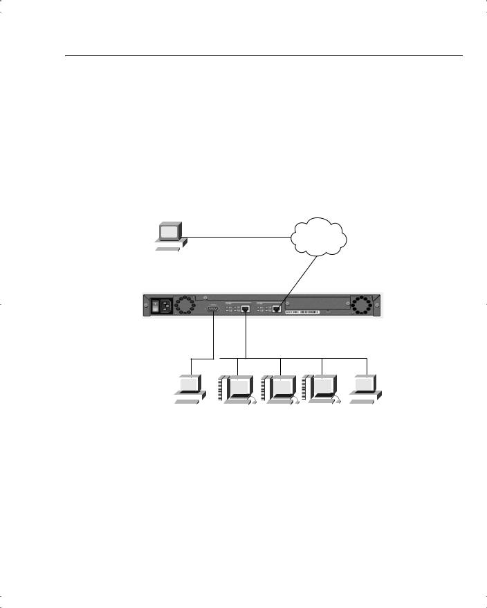
Figure 4-2 shows a typical VPN concentrator configuration using a Cisco VPN 3005 Concentrator. The Public interface connects to the Internet through a security device such as a firewall or border router (not shown in this diagram). The Private interface connects to the local network, in this case supporting Domain Name System (DNS), Windows Internet Naming Service (WINS), and DHCP servers. On those models that have a third interface, you can establish a demilitarized zone (DMZ), which could contain some of these elements and, most likely, your Internet server. Connection to the Public and Private 10/100-Mbps Ethernet interfaces is done using UTP/STP CAT-5 cabling with RJ-45 connectors.
Figure 4-2 VPN 3005 Concentrator Configuration
Internet
|
|
|
|
|
|
|
|
|
|
|
|
VPN Client PC |
|
||||
193.14.233.107 |
172.16.1.0 |
||||
|
|
|
|
|
|
|
|
|
|
|
VPN |
|
|
|
|
|
Public Network |
192.168.1.0 VPN
Private Network
|
|
|
|
|
|
|
|
|
|
|
|
|
|
|
|
|
|
|
|
|
|
|
|
|
|
|
|
|
|
|
|
|
|
|
|
|
|
|
|
|
|
|
|
|
|
|
|
|
|
|
|
|
|
|
|
|
|
|
|
|
|
|
|
|
|
|
|
|
|
|
|
|
|
|
|
|
|
|
|
|
|
|
|
|
|
|
|
|
|
|
|
|
|
|
|
|
|
|
|
|
|
|
|
|
|
|
|
|
|
|
|
|
|
|
|
|
|
|
|
Console |
|
|
DNS |
|
WINS |
|
DHCP |
Administrator |
|||||||||||||||||||||
|
|
|
|
|
|
192.168.1.20 |
|
192.168.1.22 |
|
192.168.1.24 |
Workstation |
||||||||||||||||||
|
|
|
|
|
|
|
|
|
|
|
|
|
|
|
|
|
|
|
|
|
|
|
192.168.1.103 |
||||||
You need to attach a console for the initial configuration. The console port takes a standard straight-through RS-232 serial cable with a female DB-9 connector, which Cisco supplies with the system. Once the Private interface has been configured, you can access the concentrator from your administrator workstation using a web browser such as Internet Explorer or Netscape Navigator.
In addition to the physical connections, you also need to plan your IKE phase 1 and phase 2 settings. If you are going to be using preshared keys, you must select that key as well. The


16 Chapter 4: Configuring Cisco VPN 3000 for Remote Access Using Preshared Keys
Once you have entered the correct login name and password, the concentrator displays a welcome screen, as shown in Example 4-1.
Example 4-1 Quick Configuration Welcome Screen
Welcome to
Cisco Systems
VPN 3000 Concentrator Series
Command Line Interface
Copyright (C) 1998-2001 Cisco Systems, Inc.
--: Set the time on your device. The correct time is very important,
--: so that logging and accounting entries are accurate.
--: Enter the system time in the following format:
-- : HH:MM:SS. Example 21:30:00 for 9:30 PM
> Time
Quick -> [ 08:57:13 ]
Setting the System Time, Date, and Time Zone
At this point, the concentrator is waiting for you to verify the current time by pressing Enter or to type in a new time, as shown in Example 4-2. Notice that the system prompt changes to Quick -> to indicate that the system is waiting for you to confirm or enter data. The following example also shows the entries that are required (in boldface type) to complete the configuration of the date, time zone, and daylight-savings time support information.
Example 4-2 Setting the System Time and Date
Quick -> [ 08:57:13 ] 08:15:22
-- : Enter the date in the following format.
-- : MM/DD/YYYY Example 06/12/1999 for June 12th 1999.
> Date
Quick -> [ 03/29/2002 ] 09/01/2002
--: Set the time zone on your device. The correct time zone is very
--: important so that logging and accounting entries are accurate.
--: Enter the time zone using the hour offset from GMT:
-- : -12 |
: |
Kwajalein |
-11 |
: Samoa |
-10 |
: Hawaii |
-9 |
: Alaska |
|
-- : |
-8 |
: |
PST |
-7 |
: MST |
-6 |
: CST |
-5 |
: EST |
-- : |
-4 |
: |
Atlantic |
-3 |
: Brasilia |
-2 |
: Mid-Atlantic |
-1 |
: Azores |


VPN Concentrator Configuration 19
Example 4-4 Saving Configuration Settings and Exiting the CLI (Continued)
2)Modify Ethernet 2 IP Address (Public)
3)Save changes to Config file
4)Continue
5)Exit
Quick -> 5
The concentrator only presents the Quick Configuration process upon initial bootup using the default configuration. After you have configured the concentrator, the normal CLI menus look as follows:
Model 3005 menu:
1)Modify Ethernet 1 IP Address (Private)
2)Modify Ethernet 2 IP Address (Public)
3)Configure Expansion Cards
4)Save changes to Config file
5)Continue
6)Exit
Quick -> _
Model 3015–3080 menu:
1)Modify Ethernet 1 IP Address (Private)
2)Modify Ethernet 2 IP Address (Public)
3)Modify Ethernet 3 IP Address (External)
4)Configure Expansion Cards
5)Save changes to Config file
6)Continue
7)Exit
Quick -> _
If you need to go through the Quick Configuration again for any reason, simply select the
Reboot with Factory/Default Configuration option from the Administration | System Reboot menu in the VPN 3000 Concentrator Manager.
This finishes the CLI configuration steps. The remainder of the configuration steps are completed using the Cisco VPN 3000 Concentrator Manager application that is resident on each VPN concentrator and is accessible using the web browser on your administrator PC.
Quick Configuration Using the Browser-Based Manager
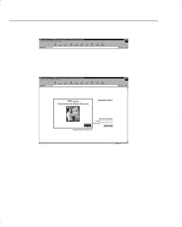
Now that you have configured the Private interface on the VPN concentrator, make sure that your workstation has an IP address on the same subnet as the concentrator and verify that you can reach the concentrator by pinging to it from the workstation. Once you have verified connectivity, open your web browser application and connect to the concentrator by entering the IP address of the concentrator in the Address field of the browser, as shown in Figure 4-3.
VPN Concentrator Configuration 21
Clicking the Install SSL Certificate hotlink takes you to the browser’s certificate installation wizard. Netscape and Microsoft browsers have slightly different installation routines, but in either case, accept the default settings presented, supply a nickname for the certificate if requested, and continue through the installation process by clicking Next or Finish. You can then immediately connect to the concentrator using HTTPS once the installation wizard has finished.
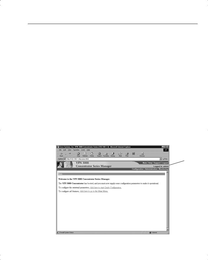
To continue with the Quick Configuration that you started from the CLI, log in with the administrator login name and password. Using the login screen shown in Figure 4-4, follow these steps:
Step 1 Position your cursor in the Login field.
Step 2 Type admin and the press Tab.
Step 3 With the cursor in the Password field, type admin again. The window displays *****.
Step 4 Click the Login button to initiate the login process.
If you make a mistake, click on the Clear button to refresh the screen so that you can start over.
After the VPN concentrator has accepted your administrator login, the screen shown in Figure 4-5 is displayed in your browser window.
Figure 4-5 First-Time Quick Start Option Menu
Applicaton
Toolbar

VPN Concentrator Configuration 25
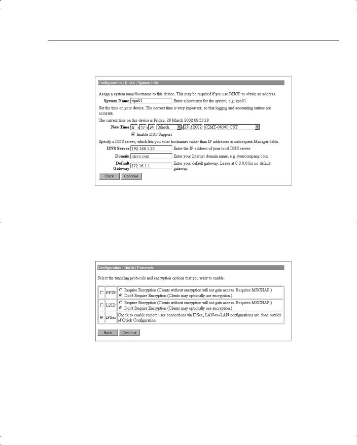
Figure 4-9 Configuration | Quick | System Info
Configuring the Tunneling Protocol
Clicking the Continue button takes you to the Protocols screen, as shown in Figure 4-10. You can select all protocols, if you like. The configuration described in this chapter works with IPSec only, so that is the only protocol selected on this screen.
Figure 4-10 Configuration | Quick | Protocols
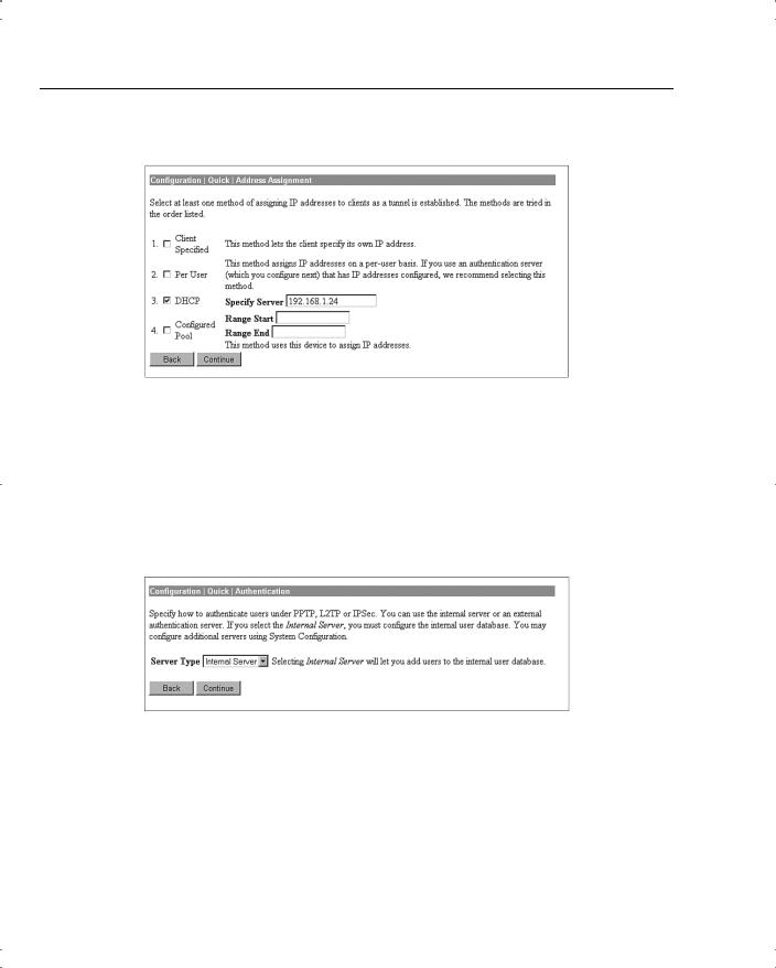
Configuring Address Assignment Method
After you have selected the protocol to use, you must select the method the VPN concentrator is to use to assign an address to clients as they establish tunnels with the concentrator. The method of address assignment selected in Figure 4-11 is to use a DHCP server.You could select multiple methods; the concentrator tries each method in order until it is successful in assigning an address to the client.
VPN Concentrator Configuration 27
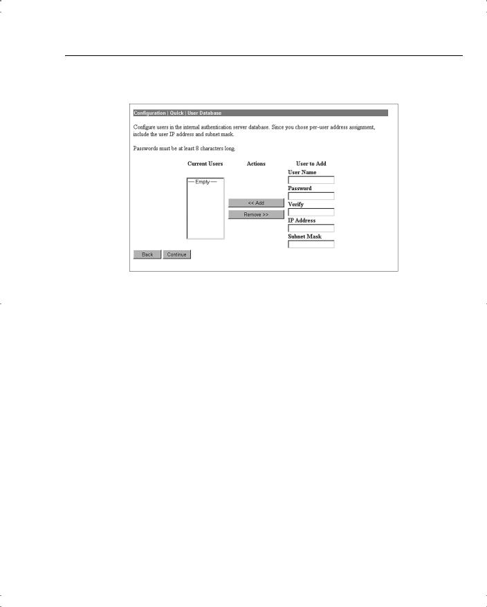
Figure 4-13 Configuration | Quick | User Database
There is a maximum combined number of groups and users that you can configure on a VPN 3000 Concentrator. The number varies by concentrator model, as shown in Table 4-2.
Table 4-2 Maximum Number of Combined Groups and Users per VPN Model
Model |
Maximum Combined Number of Groups and Users |
|
|
3005 |
100 |
|
|
3015 |
100 |
|
|
3030 |
500 |
|
|
3060 |
1000 |
|
|
3080 |
1000 |
|
|
Configuring the IPSec Tunnel Group
When you select IPSec as the tunneling protocol from the screen shown in Figure 4-10, the concentrator prompts you to define a group during the Quick Configuration phase. This group is used by every user unless you change the association later from the standard configuration section of the VPN Manager. Figure 4-14 shows the configuration information for the IPSec group. The password for this group becomes the preshared key for remote access users.
VPN Concentrator Configuration 29
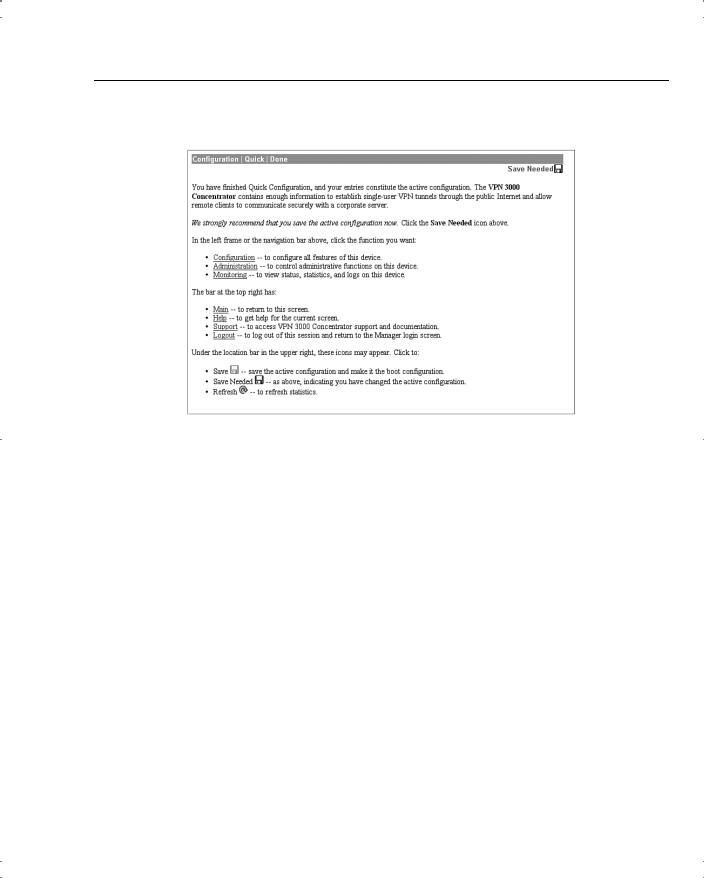
Figure 4-16 Configuration | Quick | Done
Notice the Save Needed icon in the upper-right corner of the main screen. Click that icon to save the active configuration changes you have made to the boot configuration. As you continue with additional configuration steps, this icon appears from time to time. As you can see from Figure 4-16, the icon can display Save, Save Needed, or Refresh depending on the type of screen you are on and whether you have made modifications to the active configuration.
As with most Cisco products, configuration changes are done to the active configuration and take effect immediately. To ensure that your changes are still in effect after a system reboot, you must copy the active configuration to the boot configuration. The VPN Manager’s Save Needed reminder is a nice touch, providing a gentle reminder and an easy method of execution.
Clicking the Save Needed icon executes the requested save and provides you with a status screen. Figure 4-17 shows the screen that is returned upon the completion of a successful save. After you clear this screen by clicking the OK button, VPN Manager displays the Main Menu.
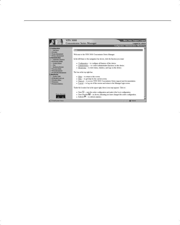
In addition to the Save, Save Needed, and Refresh options, the Configuration | Quick | Done screen shows Configuration, Administration, and Monitoring in the upper-left corner (refer to Figure 4-16). These three keys are the primary navigation tools for the daily VPN Manager functions. Similar to a directory display from a product such as Microsoft Windows Explorer,

VPN Concentrator Configuration 31
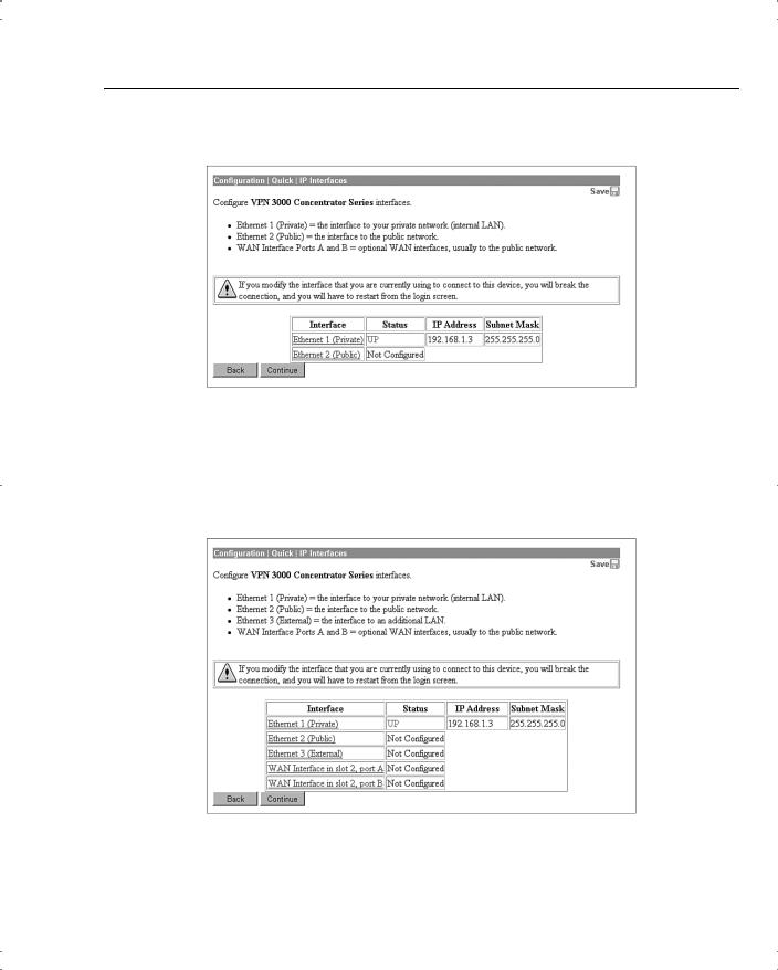
Figure 4-18 IPSec Configuration
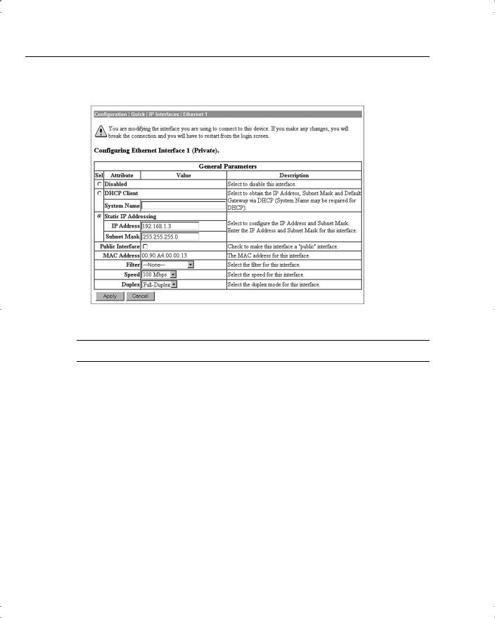
The interfaces have already been configured using the Quick Configuration option. If you chose to use internal authentication, the Quick Configuration wizard then asked you to enter usernames and passwords and then requested a group name to use for IPSec traffic.
Recall from previous chapters that there is a hierarchy to the way groups are used on the Cisco VPN 3000 Concentrator. The following basic rules govern group usage:
•Groups and users have attributes that can be modified to control how they can use the services of the concentrator.
•Users are always members of groups, and groups are always members of the Base Group. The Base Group is a default group that cannot be deleted but which can be modified.
•Inheritance rules state that, by default, users inherit rights from groups, and groups inherit rights from the Base Group.
•A user can only be a member of one concentrator group and, if not explicitly assigned to a different group, is a member of the Base Group by default.
•Users and groups have names and passwords.
•If you change the attributes of a group, it affects all group members.
•If you delete a group, user membership reverts to the Base Group.
32 Chapter 4: Configuring Cisco VPN 3000 for Remote Access Using Preshared Keys
|
Because the Base Group had not been modified before Quick Configuration set up the new |
|
group for IPSec use, that new group has default settings that it inherited from the Base Group. |
|
Additionally, all the users that you created were placed in this single group. That might be |
|
adequate for your organization. The final step you need to perform to set up the concentrator |
|
for remote access using preshared keys is to validate the entries that were placed in the IPSec |
|
group. |
|
|
NOTE |
The discussions in this chapter assume that you would be performing the configuration on a new |
|
concentrator. You could be setting up remote access services on a concentrator that has been |
|
used for other purposes, such as LAN-to-LAN VPNs. In that case, you would start at this point |
|
in the configuration process. While this discussion looks at modifying the group that was |
|
established through Quick Configuration, you would simply need to add a new group from the |
|
Configuration | User Management | Groups screen. |
|
|
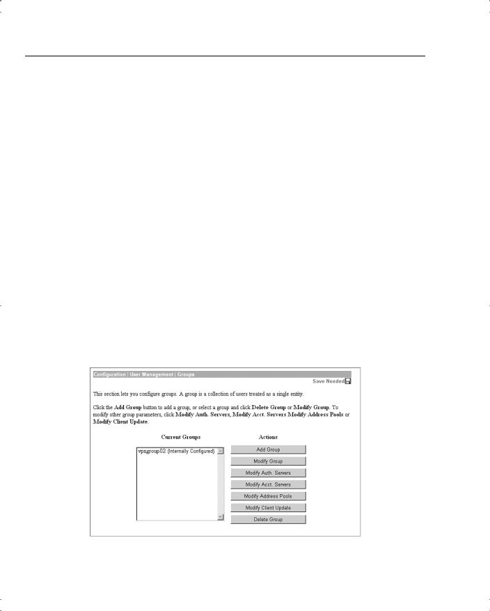
To modify the settings for the IPSec group previously created, work down to the Configuration | User Management | Groups screen (see Figure 4-19). In this screen, you find the vpngroup02 group listed in the Current Groups window. There are internal and external groups. External groups are those that would be used with external authentication servers such as RADIUS or NT Domain. The vpngroup02 group is an internal group and is to be used with internal database users.
Figure 4-19 Configuration | User Management | Groups
VPN Concentrator Configuration 33
Modify Groups—Identity Tab
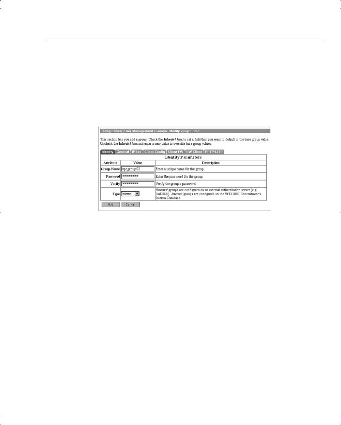
To modify the group, click the group to highlight it, and then click the Modify Group button. The screen shown in Figure 4-20 shows the Modify screen for an internal group. Internal groups have multiple tabs. External groups only have the Identity tab. The information in this screen should match the data you entered during Quick Configuration. If not, you can correct it here. When everything looks correct, click the General tab.
Figure 4-20 Configuration | User Management | Groups | Modify > Identity
Modify Groups—General Tab
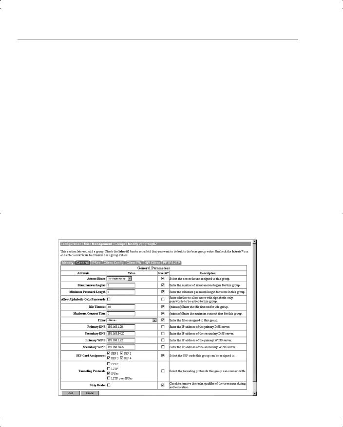
Figure 4-21 depicts the General tab for the group’s Modify function. Notice that each attribute listed has a Value, Inherit?, and Description column. If the Inherit? box is checked, that attribute’s value is inherited from the Base Group, regardless of what you enter into the Value field. To change the value for an attribute, uncheck the Inherit? box.
The following information is shown on the General tab:
•Access Hours—Selected from the drop-down menu, this attribute determines when the concentrator is open for business for this group. Currently set to No Restrictions, you could also select Never, Business Hours (9 a.m. to 5 p.m., Monday through Friday), or named access hours that you created elsewhere in the VPN Manager.
•Simultaneous Logins—Default is 3. Minimum is 0. There is no upper limit, but you should limit this value to 1 for security purposes.
•Minimum Password Length—The allowable range is 1 to 32 characters. A value of 8 provides a good level of security for most applications.
•Allow Alphabetic-Only Passwords—Notice that the Inherit? box has been unchecked. The default is to allow alphabetic-only passwords, which is not a good idea. This value has been modified.
•Idle Timeout—A value of 30 minutes is good here. The minimum allowable value is 1 and the maximum is a value that equates to over 4000 years! 0 disables idle timeout.
34Chapter 4: Configuring Cisco VPN 3000 for Remote Access Using Preshared Keys
•Maximum Connect Time—0 disables maximum connect time. The range here is again 1 minute to over 4000 years.
•Filter—Filters determine whether IPSec traffic is permitted or denied for this group. There are three default filters: Public, Private, and External. You can select from those or from any that you can define in the drop-down box. The default None option permits IPSec to handle all traffic.
•Primary/Secondary DNS/WINS—These have been modified from the Base Group’s default settings.
•SEP Card Assignment—Some models of the VPN concentrator can contain up to four Scalable Encryption Processing (SEP) modules that handle encryption functions. This attribute allows you to steer the IPSec traffic for this group to specific SEPs to perform your own load balancing.
•Tunneling Protocols—IPSec has been selected, but you could allow the group to use Point-to-Point Tunneling Protocol (PPTP), Layer 2 Tunneling Protocol (L2TP), and L2TP over IPSec as well.
•Strip Realm—The default operation of the VPN concentrator verifies users against the internal database using a combination of the username and realm qualifier, as in username@group. The @group portion is called the realm. You can have the VPN concentrator use name only by checking the value for this attribute.
Figure 4-21 Configuration | User Management | Groups | Modify > General

VPN Concentrator Configuration 35
Modify Groups—IPSec Tab
Clicking the IPSec tab brings up the screen shown in Figure 4-22. The attributes on this screen are as follows:
•IPSec SA—For remote access clients, you must select an IPSec Security Association (SA) from this list of available combinations. If you have created additional SA types, those are also displayed here as selection options. The client and server negotiate an SA that governs authentication, encryption, encapsulation, key management, and so on based on your selection here.
The following are the default selections supplied by the VPN concentrator:
—None—No SA is assigned.
—ESP-DES-MD5—This SA uses DES 56-bit data encryption for both the IKE tunnel and IPSec traffic, ESP/MD5/HMAC-128 authentication for IPSec traffic, and MD5/HMAC-128 authentication for the IKE tunnel.
—ESP-3DES-MD5—This SA uses Triple-DES 168-bit data encryption and ESP/MD5/HMAC-128 authentication for IPSec traffic, and DES-56 encryption and MD5/HMAC-128 authentication for the IKE tunnel.
—ESP/IKE-3DES-MD5—This SA uses Triple-DES 168-bit data encryption for both the IKE tunnel and IPSec traffic, ESP/MD5/HMAC-128 authentication for IPSec traffic, and MD5/HMAC-128 authentication for the IKE tunnel.
—ESP-3DES-NONE—This SA uses Triple-DES 168-bit data encryption and no authentication for IPSec traffic, and DES-56 encryption and MD5/HMAC-128 authentication for the IKE tunnel.
—ESP-L2TP-TRANSPORT—This SA uses DES 56-bit data encryption and ESP/MD5/HMAC-128 authentication for IPSec traffic (with ESP applied only to the transport layer segment), and it uses Triple-DES 168-bit data encryption and MD5/HMAC-128 for the IKE tunnel. Use this SA with the L2TP over IPSec tunneling protocol.
—ESP-3DES-MD5-DH7—This SA uses Triple-DES 168-bit data encryption and ESP/MD5/HMAC-128 authentication for both IPSec traffic and the IKE tunnel. It uses Diffie-Hellman Group 7 (ECC) to negotiate Perfect Forward Secrecy.
This option is intended for use with the movianVPN client, but you can use it with other clients that support D-H Group 7 (ECC).
•IKE Peer Identity Validation—This option applies only to VPN tunnel negotiation based on certificates. This field enables you to hold clients to tighter security requirements.

36Chapter 4: Configuring Cisco VPN 3000 for Remote Access Using Preshared Keys
•IKE Keepalives—Monitors the continued presence of a remote peer and notifies the remote peer that the concentrator is still active. If a peer no longer responds to the keepalives, the concentrator drops the connection, preventing hung connections that could clutter the concentrator.
•Tunnel Type—You can select either LAN-to-LAN or Remote Access as the tunnel type. If you select LAN-to-LAN, you do not need to complete the remainder of this screen.
•Group Lock—Checking this field forces the user to be a member of this group when authenticating to the concentrator.
•Authentication—This field selects the method of user authentication to use. The available options are as follows:
—None—No user authentication occurs. Use this with L2TP over IPSec.
—RADIUS—Uses an external RADIUS server for authentication. The server address is configured elsewhere.
—RADIUS with Expiry—Uses an external RADIUS server for authentication. If the user’s password has expired, this method gives the user the opportunity to create a new password.
—NT Domain—Uses an external Windows NT Domain system for user authentication.
—SDI—Uses an external RSA Security, Inc., SecurID system for user authentication.
—Internal—Uses the internal VPN concentrator authentication server for user authentication.
•IPComp—This option permits the use of the Lempel Zif Stac (LZS) compression algorithm for IP traffic developed by Stac Electronics. This can speed connections for users connecting through low-speed dial-up circuits.
•Reauthentication on Rekey—During IKE phase 1, the VPN concentrator prompts the user to enter an ID and password. When you enable reauthentication, the concentrator prompts for user authentication whenever a rekey occurs, such as when the IKE SA lifetime expires. If the SA lifetime is set too short, this could be an annoyance to your users, but it provides an additional layer of security.
•Mode Configuration—During SA negotiations, this option permits the exchange of configuration parameters with the client. To pass configuration information to the client, such as DNS or WINS addresses, you must enable this option. If you check this box, you need to continue to the Mode Config tab to complete the selection of attributes there.
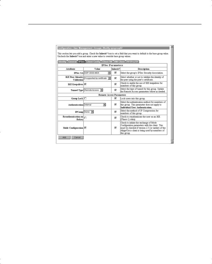
VPN Concentrator Configuration 37
Figure 4-22 Configuration | User Management | Groups | Modify > IPSec
Modify Groups—Client Config Tab
The Client Config tab screen is shown in Figure 4-23. Configuration of the attributes on this screen is only necessary if you selected Mode Configuration from the IPSec tab screen. The attributes on this page have the following meanings:
•Banner—You can enter up to a 510-character greeting banner that is displayed to IPSec software clients each time they log in to the system.
•Allow Password Storage on Client—This option allows the client PC to store the user’s password. For security reasons, this is not a good policy. The default is to have this capability disabled.
•IPSec over UDP—This option permits clients to connect to the VPN concentrator via UDP through a firewall or router using NAT.
•IPSec over UDP Port—This attribute lets you set the port to use through the firewall. The default is 10,000.
38Chapter 4: Configuring Cisco VPN 3000 for Remote Access Using Preshared Keys
•IPSec Backup Servers—This attribute is used on Cisco VPN 3002 Hardware Clients and is not required for remote access users.
•Intercept DHCP Configure Message—Enable DHCP intercept to permit Microsoft Windows XP clients to perform split tunneling with the VPN concentrator. When you enable this field, the VPN concentrator replies to the Microsoft Windows XP client DHCP Inform message. This capability allows the VPN concentrator to provide the client with a subnet mask, domain name, and classless static routes for the tunnel IP address when a DHCP server is not available.
•Subnet Mask—Enter a valid subnet mask for Microsoft Windows clients requesting DHCP services.
•Split Tunneling Policy—This option, disabled by default, permits clients to specify some types of traffic as not requiring IPSec protection. This traffic is sent in clear text. The options within this attribute are as follows:
—Tunnel everything—All data use the secure IPSec tunnel.
—Allow networks in list to bypass the tunnel—All data use the secure IPSec tunnel except for data being sent to addresses on the network list. This option gives users who have elected to tunnel all traffic the ability to access devices such as printers on their local networks without having that traffic encrypted.
—Only tunnel networks in list—Uses the secure IPSec tunnel for data sent to addresses on the network list. All other traffic is sent as clear text. This option allows remote users to access public networks without requiring IPSec tunneling through the corporate network.
•Split Tunneling Network List—If you select the Allow networks in list to bypass the tunnel option, then this list is an exclusion list, allowing traffic to pass over the network without going through IPSec. If you select the Only tunnel networks in list option, then this list is an inclusion list that determines which traffic is handled via IPSec. You can establish these lists elsewhere in the concentrator, or you can use the VPN Client Local LAN option.
•Default Domain Name—If you supply a domain name here, the concentrator passes this name to the client. Fully qualified domain names sent over the IPSec tunnel have this domain name appended to the end.
•Split DNS Names—Enter a list of domain names that you want the VPN concentrator’s internal DNS server to resolve for traffic going over the tunnel. This option is useful in split-tunneling connections, permitting the internal DNS server to resolve domain names for traffic through the tunnel. The ISP-assigned DNS servers resolve DNS requests that travel in the clear to the Internet.

VPN Concentrator Configuration 39
Figure 4-23 Configuration | User Management | Groups | Modify > Client Config


VPN Concentrator Configuration 41
•Firewall—Select the firewall that members of the group are to use. The available options are as follows:
—Cisco Integrated Client Firewall—The stateful firewall built into the VPN Client.
—Network ICE BlackICE Defender—The Network ICE BlackICE Agent or Defender personal firewall.
—Zone Labs ZoneAlarm—The Zone Labs ZoneAlarm personal firewall.
—Zone Labs ZoneAlarm Pro—The Zone Labs ZoneAlarm Pro personal firewall.
—Zone Labs ZoneAlarm or ZoneAlarm Pro—Either the Zone Labs ZoneAlarm personal firewall or the Zone Labs ZoneAlarm Pro personal firewall.
—Zone Labs Integrity—The Zone Labs Integrity Client.
—Custom Firewall—This option is primarily for future use. Choose this option when you cannot use any of the previous options or when you want to combine two or more of these options. When you choose this option, you must detail your firewall selection(s) in the Custom Firewall attribute settings.
•Custom Firewall—All the supported options are currently selectable from the list available in the Firewall attribute setting. In the future, additional options might be available. At that time, you could use this section to identify those new firewalls.
—Vendor ID—You can only enter one vendor ID code in this field. Currently, the available vendor codes are Cisco Systems (Vendor ID 1), Zone Labs (Vendor ID 2), and Network ICE (Vendor ID 3).
—Product ID—For the vendor selected, you can enter multiple product ID codes in this field. When entering multiple code numbers, separate them with a comma or use a hyphen to designate a range, such as 1-3 for Zone Labs. To use all available products for a given vendor, enter 255 as the Product ID. Table 4-3 shows the current product codes.
Table 4-3 |
Custom Firewall Product Codes |
|
|
|
|
|
|
|
Vendor |
Product |
Product Code |
|
|
|
|
|
Cisco |
Cisco Integrated Client (CIC) |
1 |
|
|
|
|
|
Zone Labs |
Zone Alarm |
1 |
|
|
|
|
|
|
Zone Alarm Pro |
2 |
|
|
|
|
|
|
Zone Labs Integrity |
3 |
|
|
|
|
|
Network ICE |
BlackIce Defender/Agent |
1 |
|
|
|
|
—Description—You can enter an optional description for your custom firewall in this field.

42Chapter 4: Configuring Cisco VPN 3000 for Remote Access Using Preshared Keys
•Firewall Policy—You can select from three different methods for administering the firewall policy for your VPN Client systems. Those methods are as follows:
—Policy Defined by Remote Firewall (AYT)—The user of the VPN Client system has established firewall policy settings for a personalized firewall that runs on the user’s system. That firewall can be a third-party firewall that works with the Cisco VPN Client and VPN concentrator. The VPN Client uses the Are You There (AYT) enforcement mechanism to periodically poll the firewall. If the firewall doesn’t respond to the periodic “Are you there?” messages, the VPN Client drops the connection to the VPN concentrator. A system administrator can initially configure and install the firewall for these users, but each user is allowed to configure his or her own policies beyond the initial settings. This option is available for use with the Network ICE BlackIce Defender, Zone Labs ZoneAlarm, and Zone Labs ZoneAlarm Pro firewall products.
—Policy Pushed (CPP)—When a corporation’s security policy mandates that all VPN Clients use the same firewall policy, the system administrator can configure the VPN concentrator to push a centralized, standardized firewall policy to each VPN Client, which then passes the policy on to the local firewall for enforcement. The administrator creates a set of traffic management rules on the VPN concentrator, associates the rules with a filter, and designates the filter as the firewall policy from the drop-down window for this attribute. This type of firewall policy management is called push policy or Central Protection Policy (CPP). This option is available for use with the Cisco Integrated Client Firewall, Zone Labs ZoneAlarm, and Zone Labs ZoneAlarm Pro firewall products.
—Policy from Server—You can use the Zone Labs Integrity Server (IS), a standalone firewall server, to manage firewall policy management and enforcement through the VPN Client. A centralized firewall policy is maintained on the IS. The IS then pushes this policy to each monitored VPN Client host and then monitors the use of the policy on those hosts. The Zone Labs IS also communicates with the VPN concentrator to manage connections and share session, user, and status information. This option is only available for the Zone Labs Integrity Server firewall product.
Modify Groups—HW Client Tab
Cisco VPN 3002 Hardware Clients provide additional authentication capabilities for peer and user authentication. The VPN 3002 Hardware Client communicates with the VPN concentrator to establish the tunnel and the user systems connect to the hardware client via Ethernet connections. The user systems do not require the VPN Client.
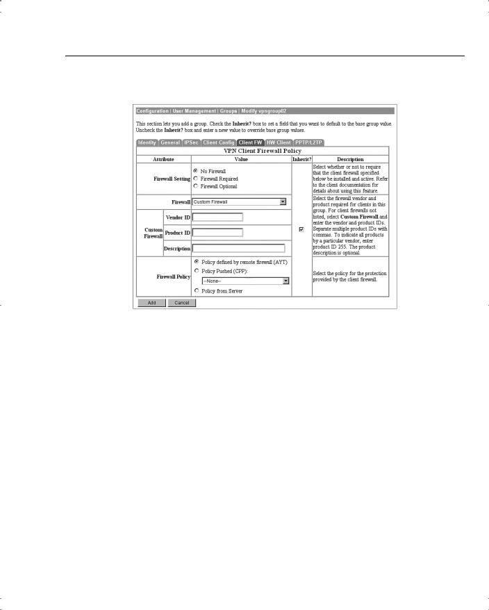
VPN Concentrator Configuration 43
Figure 4-24 Configuration | User Management | Groups | Modify > Client FW
When you configure the VPN 3002 Hardware Client for the IPSec tunneling protocol, you enter the IPSec group name and password that you configured on the VPN concentrator onto the Configuration | System | Tunneling Protocols | IPSec screen of the VPN 3002 Hardware Client. You must also enter a single username and password on that same screen, which are used to establish user authentication for all users connected to the VPN 3002 Hardware Client. Both the group name and username must be valid to establish the IPSec tunnel. Once the VPN 3002 Hardware Client and the VPN concentrator have established the VPN tunnel, any users connected to the hardware client can use the secure tunnel.
To provide additional security, you can enable interactive authentication for the establishment of the IPSec tunnel and for interactive user authentication. The HW Client tab, shown in Figure 4-25, permits you to enable the following authentication features:
•Require Interactive Hardware Client Authentication—When this field is checked, the username and password that were configured on the VPN 3002 Hardware Client are ignored. The first user connected to the VPN 3002 Hardware Client that wants to begin using secure IPSec communications is prompted to enter a valid username and password. The method of authentication was selected earlier on the group’s IPSec tab. Once the initial user establishes the IPSec tunnel, no other users are prompted for the tunnel authentication username and password.
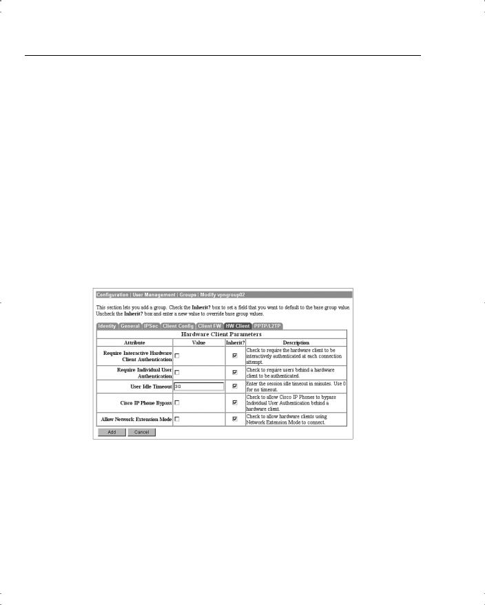
44Chapter 4: Configuring Cisco VPN 3000 for Remote Access Using Preshared Keys
•Require Individual User Authentication—You can also require all other users connected to the VPN 3002 Hardware Client to authenticate before using the IPSec tunnel by checking this attribute box. Each user is prompted for a username and password and is authenticated using whatever method the IPSec group requires.
•User Idle Timeout—The default idle timeout for a user’s connection is 30 minutes. The smallest idle timeout period you can use is 1 minute.You can enter 0 to tell the concentrator to never drop an idle connection. When a user’s connection has been idle for the period of time specified by the idle timeout period, the concentrator drops the connection.
•Cisco IP Phone Bypass—Checking this field tells the VPN concentrator not to negotiate individual user authentication for IP phones.
•Allow Network Extension Mode—You can configure the VPN 3000 Concentrator to support Network Extension mode with VPN 3002 Hardware Clients in site-to-site
networks by checking this field. The VPN 3002 Hardware Client must also be configured to support network extension mode, or the two devices can never connect to one another. The default connection mode is Port Address Translation (PAT).
Figure 4-25 Configuration | User Management | Groups | Modify > HW Client
Modify Groups—PPTP/L2TP Tab
If you selected PPTP, L2TP, or L2TP over IPSec as an allowable tunneling protocol to be used for VPN connections, you might need to make adjustments to the attributes displayed on the PPTP/L2TP Tab, shown in Figure 4-26. Client and VPN concentrator settings must match during VPN tunnel negotiations, or the tunnel is not established. The following attributes are shown on this screen:
•Use Client Address—You can allow clients to supply their own address for the client end of the VPN tunnel. This is not a good idea from a security perspective, so be careful about

VPN Concentrator Configuration 45
enabling this capability. The default mode for this attribute is disabled, forcing the VPN concentrator to supply the address through one of the various means available to the concentrator.
•PPTP Authentication Protocols—During tunnel negotiation, prospective peers generally authenticate one another through some mechanism. By checking none of the available options, you can permit the tunnel to be negotiated with no authentication, but you should only use that for test purposes. The available authentication protocols are as follows:
—PAP—The Password Authentication Protocol (PAP) passes the username and password in clear text and is therefore not secure. Although this is the default setting, it is not a recommended choice for a secure environment. PAP does not provide data encryption.
—CHAP—The Challenge-Handshake Authentication Protocol (CHAP) is also permitted by default, but is also not particularly secure. In response to a challenge from the server, the client encrypts the challenge plus password and returns that to the server along with the clear text username. CHAP does not provide data encryption.
—MSCHAPv1—The Microsoft Challenge-Handshake Authentication Protocol version 1 (MSCHAPv1) is more secure than CHAP because the server only stores and compares encrypted passwords. MSCHAPv1 can encrypt data using the Microsoft Point-to-Point Encryption (MPPE) Protocol.
—MSCHAPv2—The Microsoft Challenge-Handshake Authentication Protocol version 2 (MSCHAPv2) is a step up from MSCHAPv1 because it requires mutual client-server authentication. MPPE can also be used here for data encryption using keys that are unique for each session. MSCHAPv2 also uses different keys for the send and receive functions.
—EAP Proxy—The Extensible Authentication Protocol (EAP) Proxy lets the VPN concentrator offload the authentication process to an external RADIUS server, providing additional authentication services such as EAP/MD5, Smartcards and certificates (EAP/TLS), and RSA SecurID (EAP/SDI). EAP Proxy does not support encryption.
•PPTP Encryption—Select the type of PPTP encryption that you want to use from these options:
—Required—If you select this option, clients must use MPPE encryption. This means that you can only select MSCHAPv1 and MSCHAPv2 as the allowable authentication protocols when using this option. You must also select either 40-bit and/or 128-bit encryption in this category.
—Require Stateless—Under this encryption scheme, the encryption key is changed with each packet transferred.
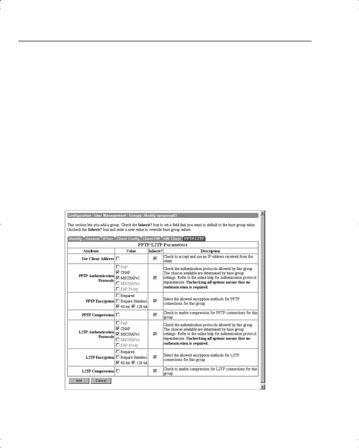
46Chapter 4: Configuring Cisco VPN 3000 for Remote Access Using Preshared Keys
—40-bit—Clients can use the RSA RC4 encryption algorithm using a 40-bit key when this option is checked.
—128-bit—Clients can use the RSA RC4 encryption algorithm using a 128-bit key when this option is checked.
•PPTP Compression—If many of your clients connect via dial-up connections, you might want to enable PPTP compression to decrease the amount of data being transferred. If you enable compression, the Microsoft Point-to-Point Compression (MPPC) algorithm is used.
•L2TP Authentication Protocols—L2TP authentication protocol options are the same as the PPTP options previously discussed.
•L2TP Encryption—L2TP encryption options are the same as the PPTP options previously discussed.
•L2TP Compression—L2TP compression options are the same as the PPTP options previously discussed.
Figure 4-26 Configuration | User Management | Groups | Modify > PPTP/L2TP


VPN Concentrator Configuration 49
•Redundancy—Virtual Router Redundancy Protocol parameters
•Reverse Route Injection—Reverse Route Injection global parameters
Routing Information Protocol (RIP) and interface-specific OSPF parameters are configured on the network interfaces. You access the interfaces to make those configurations through the Configuration | Interfaces screen.
Configuration | System | Management Protocols
The Configuration | System | Management Protocols portion of the VPN Manager allows you to control various management protocols and servers. These utilities can be an asset to you in managing your total network. Those management protocols are as follows:
•FTP—File Transfer Protocol
•HTTP/HTTPS—Hypertext Transfer Protocol and HTTP over SSL (Secure Sockets Layer) protocol
•TFTP—Trivial File Transfer Protocol
•Telnet—Terminal emulation protocol and Telnet over SSL
•SNMP—Simple Network Management Protocol
•SNMP Community Strings—Identifiers for valid SNMP clients
•SSL—Secure Sockets Layer Protocol
•SSH—Secure Shell
•XML—Extensible Markup Language
Configuration | System | Events
Significant occurrences within or that could affect a VPN 3000 Concentrator are classified as events. Typical events include alarms, traps, error conditions, network problems, task completions, breaches of threshold levels, and status changes. Events are stored in an event log in nonvolatile memory. Events can also be sent to a backup server via FTP or to Syslog servers. Events can be identified to trigger console messages, send e-mail messages, or send SNMP system traps.
Event attributes include class and severity level, as follows:
•Event Class—Specifies the source of the event and refers to a specific hardware or software subsystem within the VPN concentrator.
•Event Severity Level—Indicates how serious or significant the event is. Level 1 is the most significant.


VPN Concentrator Configuration 51
Configuration | User Management
Configuration | User Management is the section that you used in the “Configuring IPSec with Preshared Keys Through the VPN 3000 Concentrator Series Manager” section of this chapter to configure the group for remote access with preshared keys. In addition to working with specific groups, this section is used to configure the Base Group and to manage user accounts for the internal authentication database.
With the default settings, new groups inherit the attributes of the Base Group. Those attributes can be individually overridden for each group so that you can have a variety of groups with different properties. You could have a group using L2TP, one using IPSec with preshared keys, another using IPSec with digital certificates, another using RADIUS for user authentication, and still another using the concentrator’s internal database for user authentication.
If you are using the concentrator for internal authentication and have defined your groups, this section of the VPN Manager also allows you to create and manage user accounts. User accounts inherit the attributes of their group, and user accounts can only belong to one group. If you do not explicitly assign a user account to a group, it inherits the attributes of the Base Group.
Configuration | Policy Management
Policies control the actions of users as they connect to the VPN concentrator. User management determines which users are allowed to use the device. Policy management determines when users can connect, from where they can connect, and what kind of data are permitted in the tunnels. The section of the VPN Manager established filters that determine whether to forward or drop packets and whether to pass the traffic through a tunnel or to send it in the clear. Filters are applied to interfaces, groups, and users.
The Policy Management section contains the following sections:
•Access Hours—Establishes when remote users can access the VPN concentrator.
•Traffic Management—Controls what data traffic can flow through the VPN concentrator. Traffic Management is further divided into the following configuration sections:
—Network Lists—Allows you to group lists of networks together as single objects.
—Rules—Provides detailed parameters that let you specify the handling of data packets.
—SAs—Lets you choose the options to be used in establishing IPSec Security Associations. This is where you set the authentication, encryption, encapsulation, and SA lifetime. You can modify predefined SAs or create your own.
—Filters—Lets you combine the network lists, rules, and SAs into single packages that you can then apply to interfaces, groups, and users.
—NAT—The Cisco VPN 3000 Concentrators can perform Network Address Translation, which you would configure in this section.


54Chapter 4: Configuring Cisco VPN 3000 for Remote Access Using Preshared Keys
•IKE keepalives
•Split tunneling
•LZS data compression
Authentication features include the following:
•User authentication via the following:
—VPN concentrator internal database
—RADIUS
—NT Domain (Windows NT)
—RSA (formerly SDI) SecurID or SoftID
•Certificate Manager to manage client identity certificates
•Ability to use Entrust Entelligence certificates
•Ability to authenticate using smart cards with certificates Firewall features include the following:
•Support for Cisco Secure PIX Firewall platforms
•Support for the following personal firewalls:
—Cisco Integrated Firewall (CIF)
—ZoneAlarmPro 2.6.3.57
—ZoneAlarm 2.6.3.57
—BlackIce Agent and BlackIce Defender 2.5
•Centralized Protection Policy provides support for firewall policies pushed to the VPN Client from the VPN 3000 Concentrator.
VPN Client IPSec attributes include the following:
•Main and aggressive modes for negotiating phase 1 of establishing ISAKMP Security Associations
•Authentication algorithms:
—HMAC (Hashed Message Authentication Coding) with MD5 (Message Digest 5) hash function
—HMAC with SHA-1 (Secure Hash Algorithm) hash function
•Authentication modes:
—Preshared keys
—X.509 Digital Certificates
•Diffie-Hellman Groups 1, 2, and 5
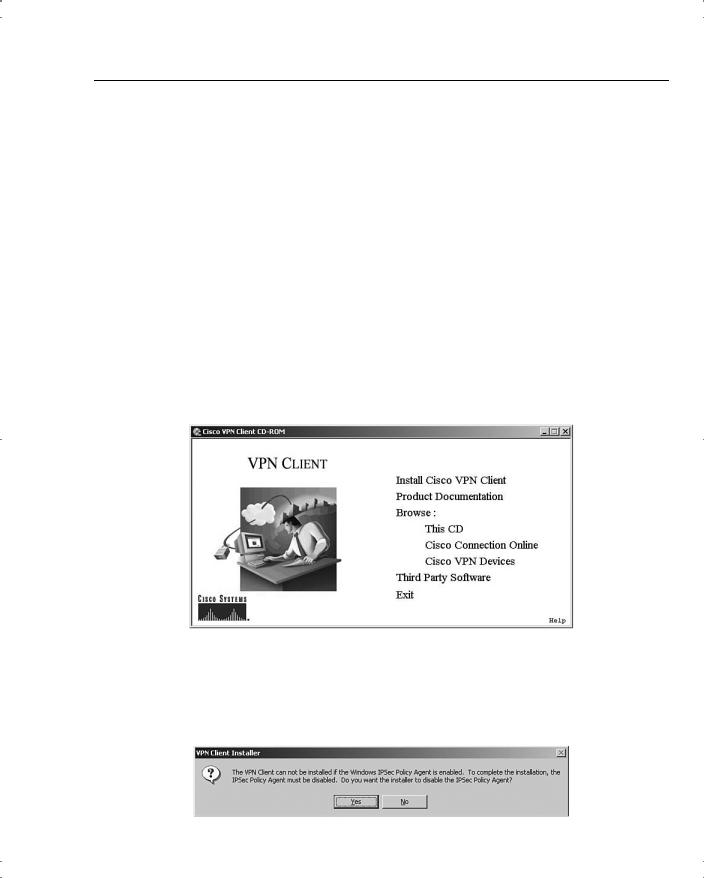
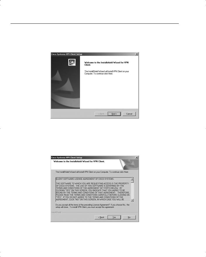
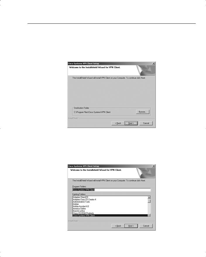
Installing and Configuring the VPN Client 57
The file location screen is displayed, as shown in Figure 4-31. To accept the default location, click Next. If not, click Browse to select the folder where the installation wizard is to install the client application.
Figure 4-31 VPN Client Install File Location
The next screen to be displayed, shown in Figure 4-32, asks you to select the Windows folder for the application. Click Next to accept the default, or select another location for the application.
Figure 4-32 VPN Client Install Windows Folder Selection
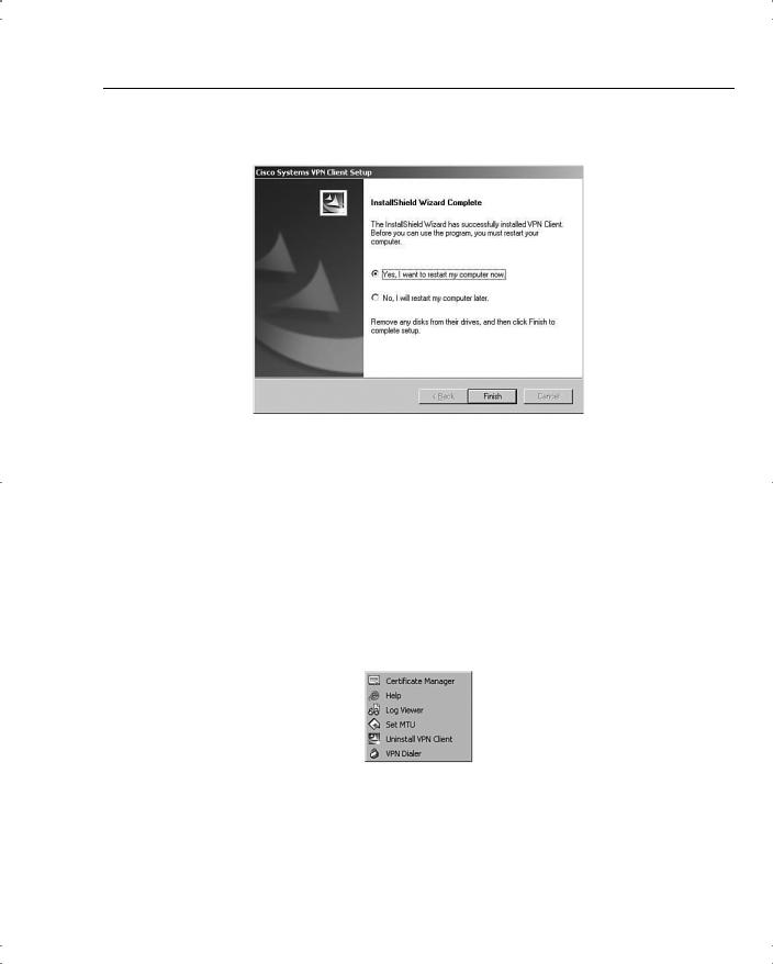
Installing and Configuring the VPN Client 59
Figure 4-35 VPN Client Installation Complete
VPN Client Configuration
The configuration process is almost as easy as the installation process. The user must enter several pieces of information. Your installation instructions should provide all the entries that your users must make.
To start the configuration process, start the VPN Client application. From the Windows Desktop, choose Start, Programs, Cisco Systems VPN Client to display the Option menu shown in Figure 4-36. The next step is not self-evident. To start the client, click the VPN Dialer menu option.
Figure 4-36 Starting the Cisco VPN Client
Figure 4-37 shows the main interface screen for the VPN Client. Notice that the Connection Entry window is blank, indicating that you have not yet configured the connection information. The Connect button is also grayed out and stays that way until you have a valid connection defined. Create the first connection entry; click New to begin that process.
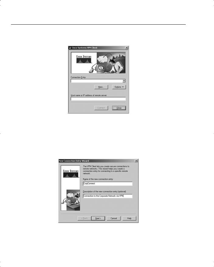
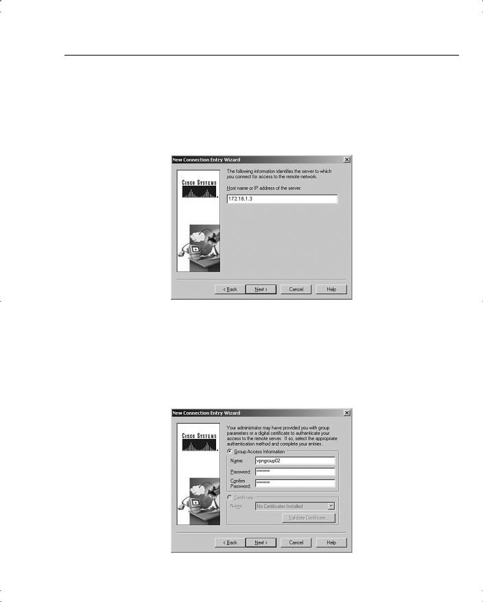
Installing and Configuring the VPN Client 61
VPN 3000 Concentrator Series Manager” section of this chapter. Enter either the IP address of the device or the fully qualified domain name (FQDN), if you know it. The public IP address of the VPN concentrator is required, so enter 172.16.1.3 to reach the concentrator you configured earlier. Click Next after you have identified the host server.
Figure 4-39 New Connection Address
Because you have not yet installed any digital certificates onto your PC, the next screen presents only one option to use for authenticating the IPSec connection. In Figure 4-40 you can see that the Certificate option is grayed out. To configure the client to use a preshared key for the IPSec connection, simply enter the IPSec group name and password in the appropriate fields of the Group Access Information section.
Figure 4-40 Entering the Preshared Key
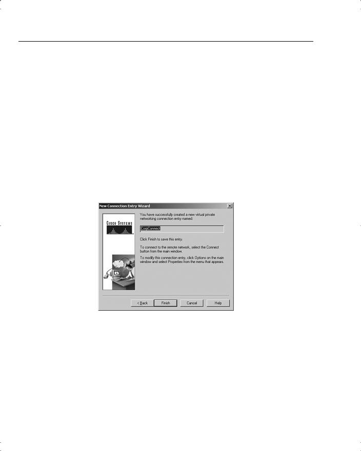
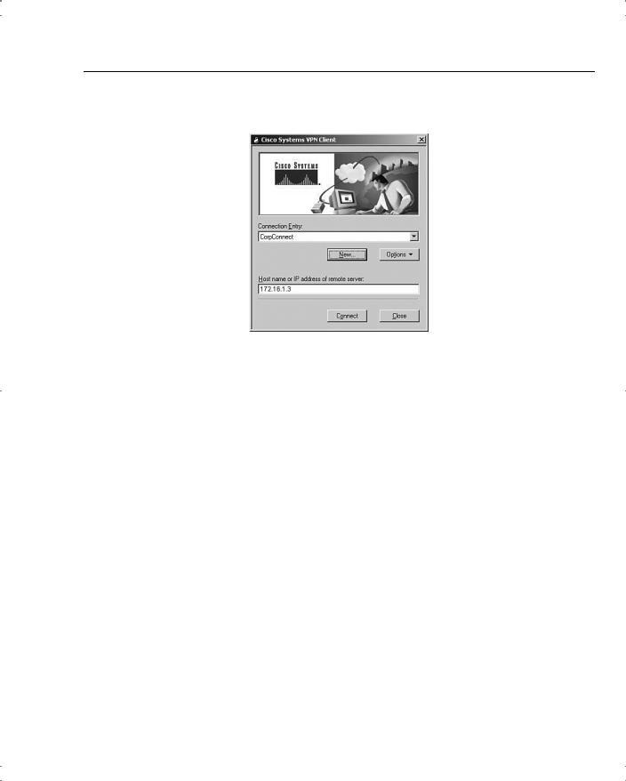
Installing and Configuring the VPN Client 63
Figure 4-42 Using the New VPN Connection
To connect to the VPN 3000 Concentrator, simply click the Connect button. The client attempts to negotiate IKE and IPSec SAs with the concentrator. If that is successful, the IPSec tunnel is created and the client prompts you for your username and password. Once that has been authenticated, you can begin using the VPN Client for secure remote access to the VPN concentrator.

64 Chapter 4: Configuring Cisco VPN 3000 for Remote Access Using Preshared Keys
Foundation Summary
The Foundation Summary is a collection of tables and figures that provides a convenient review of many key concepts in this chapter. For those of you already comfortable with the topics in this chapter, this summary could help you recall a few details. For those of you who just read this chapter, this review should help solidify some key facts. For anyone doing his or her final preparation before the exam, these tables and figures are hopefully a convenient way to review the material the day before the exam.
Types of Preshared Keys
The types of preshared keys are as follows:
•Unique—Tied to a specific IP address
•Group—Tied to a group
•Wildcard—Not tied to anything
VPN 3000 Concentrator CLI Quick Configuration Steps
The steps to VPN 3000 Concentrator CLI Quick Configuration are as follows:
Step 1 Boot the VPN concentrator with default configuration.
Step 2 Login as admin/admin.
Step 3 Set the system time.
Step 4 Set the system date.
Step 5 Set the time zone.
Step 6 Set the daylight-savings time support.
Step 7 Enter an IP address for the Private interface.
Step 8 Enter a subnet mask for the Private interface.
Step 9 Select the speed of the interface.
Step 10 Select the duplex mode of the interface.
Step 11 Save and exit the CLI.

VPN Client Installation Steps 65
VPN 3000 Concentrator Browser-Based Manager Quick
Configuration Steps
The steps to the VPN 3000 Concentrator browser-based Manager Quick Configuration are as follows:
Ping the VPN concentrator from the administrator PC to verify connectivity.
Start the web browser.
Enter the address of the VPN concentrator (be sure to use https:// if you need to enable the VPN concentrator’s SSL Certificate on your browser).
Step 4 Log in as admin/admin.
Step 5 Select Click here to start Quick Configuration.
Step 6 Select hotlink to Ethernet 2 (Public) interface.
Step 7 Enter the IP address, subnet mask, speed, and duplex mode.
Step 8 Verify the system name, date, time, time zone, and DST support.
Step 9 Enter the DNS server address.
Step 10 Enter the domain name.
Step 11 Enter the default gateway address.
Step 12 Select the tunneling protocols to use—IPSec.
Step 13 Select the methods of assigning IP address for the IPSec tunnel endpoints.
Step 14 Choose the method for user authentication (Internal Server).
Step 15 Add usernames and passwords.
Step 16 Supply the IPSec group name and password.
Step 17 Change the admin password.
Step 18 Click the Save Needed icon to save the configuration changes.
VPN Client Installation Steps
The steps for installing the VPN Client are as follows:
Step 1 Insert the Cisco VPN Client CD into your CD-ROM drive.
Step 2 View the CD’s menu after Autorun starts the CD.
Step 3 Select Install Cisco VPN Client.

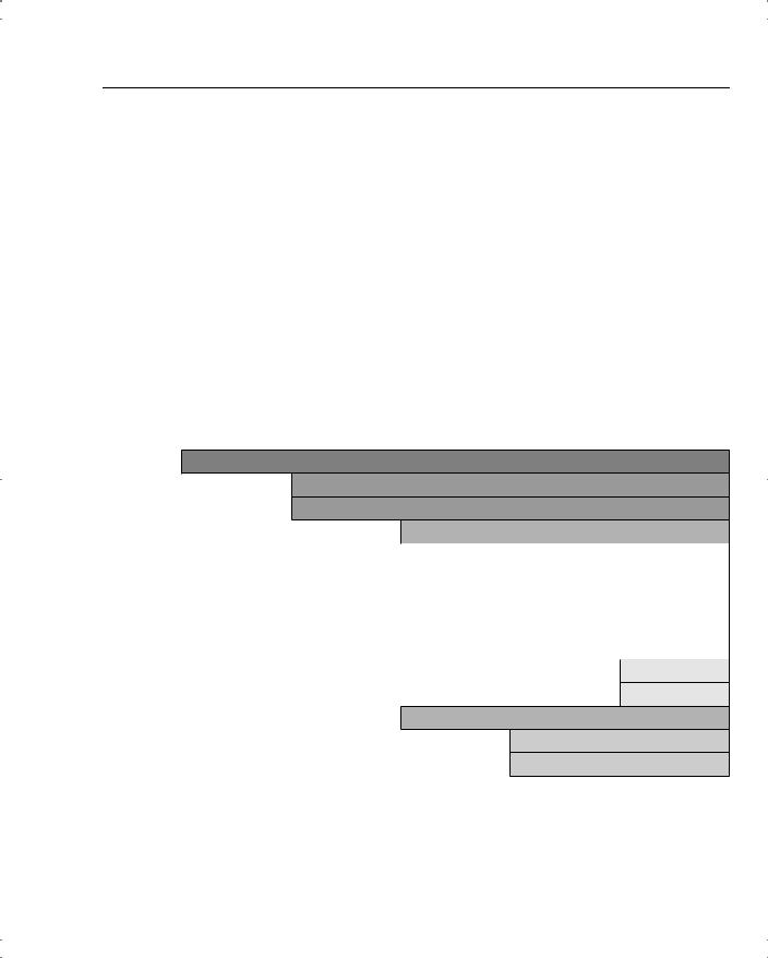
68 Chapter 4: Configuring Cisco VPN 3000 for Remote Access Using Preshared Keys
Table 4-5 Complete Expansion of the Configuration TOC (Continued)
Configuration (Continued)
>System (Continued)
>Tunneling Protocols
>PPTP
>L2TP
>IPSec
|
|
> |
|
LAN-to-LAN |
|
|
> |
|
IKE Proposals |
|
|
> |
|
IPSec over TCP |
> |
IP Routing |
|
|
|
|
> |
Static Routes |
|
|
|
> |
Default Gateways |
|
|
|
> |
OSPF |
|
|
|
> |
OSPF Areas |
|
|
|
> |
DHCP |
|
|
|
> |
Redundancy |
|
|
|
> |
Reverse Route Injection |
||
> |
Management Protocols |
|
||
|
> |
FTP |
|
|
|
> |
HTTP/HTTPS |
|
|
|
> |
TFTP |
|
|
|
> |
Telnet |
|
|
|
> |
SNMP |
|
|
|
> |
SNMP Communities |
|
|
|
> |
SSL |
|
|
|
> |
SSH |
|
|
|
> |
XML |
|
|
|
|
|
|
|

70 Chapter 4: Configuring Cisco VPN 3000 for Remote Access Using Preshared Keys
Table 4-5 Complete Expansion of the Configuration TOC (Continued)
Configuration (Continued)
>Policy Management (Continued)
>Traffic Management (Continued)
>Filters
>NAT
> Enable
> Rules
Complete Administration Table of Contents
Table 4-6 shows the complete administration table of contents (TOC).
Table 4-6 |
Complete Expansion of the Administration TOC |
||||
|
|
|
|
|
|
|
Administration |
|
|
|
|
|
> |
Administer Sessions |
|||
|
> |
Software Update |
|
|
|
|
|
> |
|
Concentrator |
|
|
|
> |
|
Clients |
|
|
> |
System Reboot |
|
|
|
|
> |
Ping |
|
|
|
|
> |
Monitoring Refresh |
|||
|
> |
Access Rights |
|
|
|
|
|
> |
|
Administrators |
|
|
|
> |
|
Access Control List |
|
|
|
> |
|
Access Settings |
|
|
|
> |
|
AAA Servers |
|
|
|
|
|
> |
Authentication |
|
> |
File Management |
|
|
|
|
|
> |
|
Swap Config File |
|
|
|
> |
|
TFTP Transfer |
|
|
|
> |
|
File Upload |
|
|
|
> |
|
XML Export |
|
|
|
|
|
|
|

72 Chapter 4: Configuring Cisco VPN 3000 for Remote Access Using Preshared Keys
Table 4-7 Complete Expansion of the Monitoring TOC (Continued)
Monitoring (Continued)
>Statistics (Continued)
>VRRP
>SSL
>DHCP
>Address Pools
>SSH
>Load Balancing
>Compression
>Administrative AAA
>NAT
>MIP-II Stats
>Interfaces
>TCP/UDP
>IP
>RIP
>OSPF
>ICMP
>ARP Table
>Ethernet

Chapter Glossary 73
Chapter Glossary
The following terms were introduced in this chapter or have special significance to the topics within this chapter.
cookie A piece of information sent by a web server to a web browser that the browser is expected to save and send back to the web server whenever the browser makes additional requests of the web server.
Extensible Markup Language (XML) A standard maintained by the World Wide Web Consortium (W3C). It defines a syntax that lets you create markup languages to specify information structures.
JavaScript Interpreted programming language from Netscape. Used on websites for such things as pop-up windows and image change during mouse rollover.
Network Time Protocol (NTP) Protocol built on top of TCP that ensures accurate local timekeeping with reference to radio and atomic clocks located on the Internet. This protocol is capable of synchronizing distributed clocks within milliseconds over long time periods.
Remote Authentication Dial-In User Service (RADIUS) Database for authenticating dial-up users and for tracking connection time.
Reverse Route Injection (RRI) Used to populate the routing table of an internal router running OSPF or RIP for remote VPN clients or LAN-to-LAN sessions.
Scalable Encryption Processing (SEP) VPN concentrator modules that perform hardwarebased cryptographic functions, including random number generation, hash transforms (MD5 and SHA-1) for authentication, and encryption and decryption (DES and Triple-DES).
Security Dynamics International (SDI) authentication Third-party authentication services using token cards.
Secure Shell (SSH) Sometimes called Secure Socket Shell, a UNIX-based command interface and protocol for gaining access to a remote computer securely.
Secure Sockets Layer (SSL) Encryption technology for the web used to provide secure transactions, such as the transmission of credit card numbers for e-commerce.
Virtual Router Redundancy Protocol (VRRP) In installations of two or more VPN concentrators in a parallel, redundant configuration, VRRP provides automatic switchover to a backup system in case the primary system is out of service, thus ensuring user access to the VPN.
VPN concentrator Any of the Cisco VPN 3000 Series Concentrators.
VPN Manager Cisco VPN 3000 Concentrator Manager.

74 Chapter 4: Configuring Cisco VPN 3000 for Remote Access Using Preshared Keys
Q&A
As mentioned in Chapter 1, “All About the Cisco Certified Security Professional (CCSP),” these questions are more difficult than what you should experience on the CCSP exam. The questions do not attempt to cover more breadth or depth than the exam; however, the questions are designed to make sure you know the answer. Rather than allowing you to derive the answer from clues hidden inside the question itself, your understanding and recall of the subject are challenged. Questions from the “Do I Know This Already?” quiz from the beginning of the chapter are repeated here to ensure that you have mastered the chapter’s topic areas. Hopefully, these questions will help limit the number of exam questions on which you narrow your choices to two options and guess!
You can find the answers to these questions in Appendix A, “Answers to the “Do I Know This Already” Quizzes and Q&A Sections.
1Where would you normally use unique preshared keys?
2To use a web browser to access the VPN Manager application on VPN concentrators, what features must you enable on the browser?
3What information is required to configure a LAN interface on the VPN concentrator?
4What is the default administrator name and password for the GUI VPN Manager?

Q&A 75
5What options are available for addressing an IP interface on the IP Interfaces screen?
6What is the maximum number of combined groups and users that can be supported on a VPN 3015 Concentrator?
7What are the four subcategories under the Configuration option of the VPN Manager’s TOC?
8On the General tab of a group’s Add screen, what options can you select for Access Hours?
9What IPSec protocols are available from the default IPSec SA settings on the IPSec tab of the Group Add screen?
10What are the nine subcategories under the Configuration | System option in the VPN Manager’s table of contents?

76 Chapter 4: Configuring Cisco VPN 3000 for Remote Access Using Preshared Keys
11Where does the VPN concentrator store system events?
12What areas can be configured under the Traffic Management section of the Configuration | Policy Management section?
13Where do you enter the preshared key so that a VPN Client can connect to a VPN concentrator?
14What are the three types of preshared keys?
15What types of interfaces are the Public and Private VPN interfaces?
16Which interface do you need to configure using the browser-based VPN Manager?

Q&A 77
17What would you do if you needed to re-enter the Quick Configuration mode after you have completed the initial configuration of the VPN concentrator?
18When the VPN Manager’s Main window is displayed, how do you continue with the Quick Configuration that was started at the CLI?
19What methods can be selected for assigning IP addresses to the tunnel endpoints from the Quick Configuration Address Assignment screen?
20When using the VPN Manager, how can you tell that you have made changes to the active configuration?
21What is an external group in the VPN Manager system?
22What is the purpose of the SEP card assignment attribute on the General tab of the Group Add screen?
78 Chapter 4: Configuring Cisco VPN 3000 for Remote Access Using Preshared Keys
23You would like to be able to pass DNS and WINS information from the VPN concentrator to the VPN Client. What Group option can you use to accomplish this?
24What dynamic routing protocols are available on the VPN 3000 Concentrators?
25What protocol does the VPN concentrator use to update software versions on Cisco VPN 3002 Hardware Clients?
26How do you start the Cisco VPN Client installation process?
27What methods can you use for user authentication on the Cisco VPN 3000 Series Concentrators?
28What is a group preshared key?

Q&A 79
29When you boot up a Cisco VPN 3000 Concentrator with the default factory configuration, what happens?
30If you supply an address of 144.50.30.24 and want to use a 24-bit subnet mask for the Private interface on a VPN concentrator, are you able to accept the default subnet mask offered by the VPN Manager?
31What are the three major sections of the VPN Manager system?
32The Quick Configuration system has displayed the System Info screen. What information, other than system date and time, can you enter on this screen?
33What is the maximum number of combined groups and users that can be supported on a VPN 3060 Concentrator?
34From where do users inherit attributes on the VPN concentrator?

80 Chapter 4: Configuring Cisco VPN 3000 for Remote Access Using Preshared Keys
35What is the default number of simultaneous logins available to group members?
36What is the purpose of IKE keepalives?
37Where would you configure information for NTP and DHCP servers within the VPN Manager?
38What is the most significant event severity level?
39What Microsoft Windows operating systems can support the Cisco VPN Client?
40What programs are available within the VPN Client installation?
41What is a unique preshared key?

Q&A 81
42What type of cable does the console port require on VPN concentrators?
43What is the default administrator name and password for VPN concentrators?
44How do you get your web browser to connect to the VPN concentrator’s manager application?
45What is the first screen that appears when you click the Click here to start Quick Configuration option in the VPN Manager?
46If you select Internal Server as the method of user authentication, what additional screen does the Quick Configuration system give you?
47When do configuration changes become active on the Cisco VPN 3000 Series Concentrators?

82 Chapter 4: Configuring Cisco VPN 3000 for Remote Access Using Preshared Keys
48When reviewing the list of attributes for a group, what does it mean when an attribute’s Inherit? box is checked?
49What is a realm in relation to user authentication?
50What is split tunneling?
51What management protocols can you configure on the VPN concentrator?
52What is the process a VPN Client uses to connect to a VPN concentrator when load balancing is used between two or more VPN concentrators?
53What variables can you supply during the installation process of the Cisco VPN Client?

Q&A 83
54What methods can be used for device authentication between VPN peers?
55What is a wildcard preshared key?
56What information do you need to supply in the CLI portion of Quick Configuration?
57What is the last step you must take before moving from the CLI Quick Configuration mode to the browser-based Quick Configuration mode?
58What hot keys are available in the standard toolbar of the VPN Manager?
59What tunneling protocols does the VPN concentrator support?

84 Chapter 4: Configuring Cisco VPN 3000 for Remote Access Using Preshared Keys
60When you select IPSec as the tunneling protocol, what screen does Quick Configuration present?
61How many groups can a user belong to in the VPN concentrator’s internal database?
62What is the size range for user authentication passwords for internal users?
63What does the Authentication option RADIUS with Expiry provide?
64What tunneling protocol can be configured on the VPN concentrator to support the Microsoft Windows 2000 VPN client?
65How does the VPN 3000 Concentrator handle software updates for VPN Software Clients?
66How do you start the VPN Client on a Windows system?

Scenario 4-1 85
Scenarios
The following scenarios and questions are designed to draw together the content of the chapter and exercise your understanding of the concepts. There might be more than one correct answer. The thought process and practice in manipulating each concept in the scenario are the goals of this section.
Scenario 4-1
Users at one of your small branch facilities dial in to your corporate access server for access to the Internet, e-mail, and other network services. This four-user group is one of your research and development teams, and each of the four users dials in to the access server using 56-kbps modems for network services. Their work is considered top secret by upper management.
Because of the sensitive nature of their communications, you want to establish a VPN for them using IPSec.
At the same time, other users at other branch sites—your sales staff and other key personnel— frequently use laptops and home computers to connect to the corporate network through the Internet or through the access server. These users discuss sales figures and development projects and also require IPSec protection on their MS Exchange messaging and MS SQL database traffic.
You had considered using your router as a VPN server, but decided to use a Cisco VPN Concentrator because of its ability to authenticate users internally. You don’t anticipate ever having more than 50 VPN clients active in your user community at any given time, and your employee base is stable.
As the senior security architect for your organization, how would you answer these questions?
1Which VPN 3000 Concentrator would you purchase and install?
2Would you use preshared keys or digital certificates for device authentication?
3Would you depend on the internal authentication services of the VPN device, or would you use some other user authentication method?
4How would you assign VPN addresses?
5Would you permit split tunneling?
6Would you use multiple IPSec groups? If so, why?
7Which IPSec protocol would you use?
8Which encryption protocol would you use?
9Would you allow unrestricted access hours?
10What would you set for idle timeout and maximum connect time?


88 Chapter 4: Configuring Cisco VPN 3000 for Remote Access Using Preshared Keys
Scenario Answers
The answers provided in this section are not necessarily the only correct answers. They merely represent one possibility for each scenario. The intention is to test your base knowledge and understanding of the concepts discussed in this chapter.
Should your answers be different (as they likely will be), consider the differences. Are your answers in line with the concepts of the answers provided and explained here? If not, reread the chapter, focusing on the sections that are related to the problem scenario.
Scenario 4-1 Answers
1Concentrator model? The Cisco VPN 3005 Concentrator is probably adequate for this installation. If your company were growing quickly, you might opt for the 3015. It has about the same capabilities but is expandable, all the way to a 3080, if you ever needed the additional capacity.
2Type of device authentication? Because this is a chapter on preshared keys, you would opt to use preshared keys. For this small user base, the maintenance for preshared keys should not be a big concern.
3Authentication? Internal authentication was one of the reasons for choosing the concentrator over the router. The internal database keeps authentication on the same device and is flexible enough to meet the needs of this application.
4Address assignment? Set aside a pool of 100 IP addresses and let the VPN concentrator assign the IP addresses from the pool. You could use DHCP, but that brings another network device into the picture. Keep it simple.
5Split tunneling? Yes. The R&D group is going to need the Internet for research and the 56-kbps modems are going to be killers. Eliminate the need for encryption on trivial traffic to help this group out.
6Multiple IPSec groups? It would make sense to use multiple IPSec groups. Some of your users might not need split tunneling, and you could use different rules for access time, idle timeout, or maximum connect times. You might want to set up functional groups such as R&D, Sales, Engineering, Accounting, Execs, and so on. You are only constrained by the 100 combined users and groups limitation on the concentrator.
7IPSec protocol? ESP. AH is authentication only with no encryption. You would want to encrypt some of these data, especially for the R&D group.
8Encryption? Probably Triple-DES. You could choose DES, but the extra security does not cost that much more in performance.

Scenario 4-2 Answers 89
9Unlimited access? This would be a group-by-group decision. Does the R&D team work around the clock or just during business hours? Do you need to set aside a regular maintenance window for network upgrades? Do the execs need unlimited access?
10Idle timeout and maximum connect time? You probably want to drop connections after they have been idle for 20 to 30 minutes. There is no overpowering reason to establish limits on connect time. If you close the connection when it is idle, you should not have to worry about lengthy connections.
Scenario 4-2 Answers
1General tab settings for the DonutShops group:
•Access Hours—No Restrictions
•Simultaneous Logins—1, uncheck Inherit?
•Minimum Password Length—8
•Allow Alphabetic-Only Passwords—No, uncheck Inherit?
•Idle Timeout—30
•Maximum Connect Time—0
•Filter—None
•Primary DNS—192.168.44.20, uncheck Inherit?
•Secondary DNS—192.168.63.20, uncheck Inherit?
•Primary WINS—192.168.44.25, uncheck Inherit?
•Secondary WINS—192.168.63.25, uncheck Inherit?
•SEP Card Assignment—You can leave these checked. Without SEP modules, this attribute has no effect.
•Tunneling Protocols—Check only IPSec, uncheck Inherit?
•Strip Realm—Leave unchecked. You will be using an external authentication service, so this field has no effect.
2IPSec tab settings for the DonutShops group:
•IPSec SA—ESP-3DES-MD5
•IKE Peer Identity Validation—If supported by certificate
•IKE Keepalives—Enabled
•Reauthentication on Rekey—Enabled, uncheck Inherit?

90Chapter 4: Configuring Cisco VPN 3000 for Remote Access Using Preshared Keys
•Tunnel Type—Remote access
•Group Lock—Disabled
•Authentication—NT Domain, uncheck Inherit?
•IPComp—None
•Mode Configuration—Enabled


This chapter covers the following key topics:
•Adaptive Security Algorithm—This section discusses ASA, the algorithm used to construct the PIX Firewall.
•Basic Features of the PIX Firewall—This section talks about basic features available in the PIX Firewall. It builds the basis for a discussion of some of the firewall’s advanced features.
•Advanced Features of the PIX Firewall—This section details of some of the advanced security features incorporated into the PIX Firewall.
•Case Studies—This section contains case studies involving PIX Firewall implementations.


148 Chapter 8: PIX Firewall
TCP
TCP is relatively easy to inspect, because it is connection-oriented. All the firewall has to do is keep track of each session being formed, utilized, and terminated. ASA only allows for the packets conforming to the state, in which the firewall believes the connection should be in, to go through the firewall. All other packets are dropped. However, TCP has a couple of inherent weaknesses that require ASA to perform a few modifications on the TCP packets passing through it to ensure security:
•The Initial Sequence Number (ISN) generated by TCP for its connections is not random. This can result in TCP session hijacking (see case study in Chapter 14, “What Is Intrusion Detection?,” for an example of how this can be done). The ASA algorithm takes care of this problem by calculating a more random sequence number, inputting this number as the sequence number in the outgoing packets and storing the difference between the two random numbers. When return traffic for that particular packet is received, it replaces the changed sequence number with the correct one before forwarding the packet to the host on the inside private network.
•SYN flooding is a reality in TCP environments. To somewhat mitigate the problem of SYN floods occurring for servers sitting behind the firewall, ASA keeps track of the synchronization requests coming in through the firewall. If the synchronization does not result in a full-blown session in a given amount of time and/or the number of such half-open sessions increases beyond a certain limit (both are configurable), the firewall starts closing such connections.
A recent enhancement to the PIX ASA implementation (in version 5.2 and later) causes the PIX to proxy for connection attempts to servers or other resources sitting behind it (SYNs) after the number of incomplete connections through the PIX reaches a configurable limit (a limit on embryonic connections). The PIX responds to SYN requests with SYN ACKs and continues proxying the connection until the three-way TCP handshake is complete. After that, it allows the connection through to the server or resource sitting behind it on the private or DMZ network. This way, only legitimate connections are allowed to be made through the PIX, and the rest are dropped based on configurable timeouts on the PIX. This is an important feature, because it limits the exposure of the servers sitting behind the PIX to SYN floods.
Figures 8-1 and 8-2 are a step-by-step overview of how a TCP connection through the PIX is handled. Figure 8-1 illustrates the TCP transmission (initialization) process and Figure 8-2 illustrates the TCP termination process.
Figure 8-1 shows the sequence of events that take place as a host sitting behind the PIX initiates a TCP connection to the outside world. The SYN packet from the host is used to create the connection entry in the PIX because this is the first packet for the connection that this host is initiating. The PIX creates the entry after examining the rules set up for such an entry to be created. The PIX performs the necessary address translation on the packet and forwards it after saving the packet’s state information—the IP addresses, the port information,
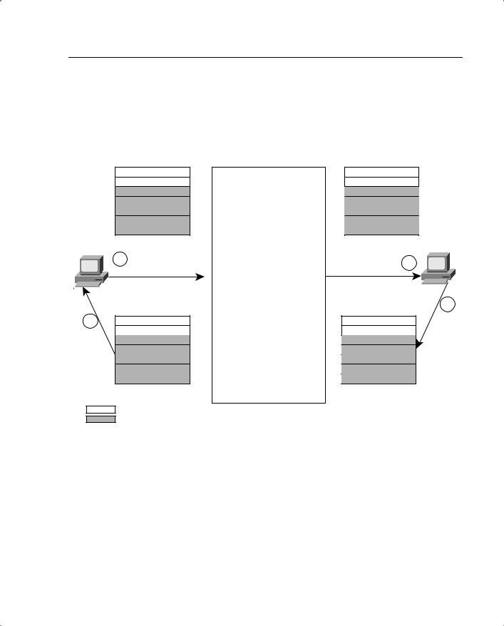
Adaptive Security Algorithm 149
the TCP flags, and the sequence number. The PIX also further randomizes the sequence number before forwarding it. PIX keeps track of the delta in the original and the new sequence number so that it can restore it in the return packet.
Figure 8-1 TCP Initiation and Transmission
Private Network |
PIX |
Public Network |
Source Addr |
10.0.0.14 |
PIX Checks Whether a |
192.150.50.24 |
|
Dest Addr |
200.150.50.11 |
200.150.50.11 |
||
Translation Exists or Not. If |
||||
Source Port |
1026 |
1026 |
||
not, It Creates One Upon |
||||
Dest Port |
23 |
23 |
||
Verifying NAT, Global Pool, |
||||
Initial Seq. # |
49091 |
49769 |
||
Access Control and |
||||
Ack |
|
|
||
|
Authentication or |
|
||
Flag |
Syn |
Syn |
||
Authorization, If Any. If OK, |
||||
|
|
|
||
|
|
a Connection Is Created. |
200.150.50.11 |
|
10.0.0.14 |
|
|
||
|
Start the embryonic |
|
||
1 |
No Data |
2 |
||
|
Connection Counter. |
|||
|
|
PIX Follows Adaptive |
|
|
|
|
Security Algorithm: |
|
|
|
|
• (Src IP, Src Port, Dest IP, |
3 |
|
|
|
Dest Port) Check |
|
|
4 |
200.150.50.11 |
• Sequence Number Check |
200.150.50.11 |
|
|
10.0.0.14 |
• Translation Check |
192.150.50.24 |
|
|
23 |
23 |
||
|
|
|||
|
1026 |
If the Code Bit Is Not Syn- |
1026 |
|
|
92513 |
Ack, PIX Drops the Packet. |
92513 |
|
|
49092 |
|
49770 |
|
|
Syn-Ack |
|
Syn-Ack |
|
= TCP Header |
|
|
||
= IP Header |
|
|
||
The return traffic sent to the host arrives at the PIX with the TCP flag set to SYN-ACK and the sequence number incremented by 1. PIX ASA looks through its state information tables and verifies that the information provided by this packet is what it would have expected from a return packet to the one that was originally sent. Because this is indeed the case, PIX changes the sequence number to take out the change it had made while randomizing the sequence number of the initial packet that was sent out, modifies the IP addresses and port information in accordance with its NAT tables, and forwards the packet on to the host that originated the first packet.
After the TCP initial three way handshake is complete, PIX tracks the packet flow for the TCP connection established through it, allowing only legitimate packets belonging to the flow to come back.
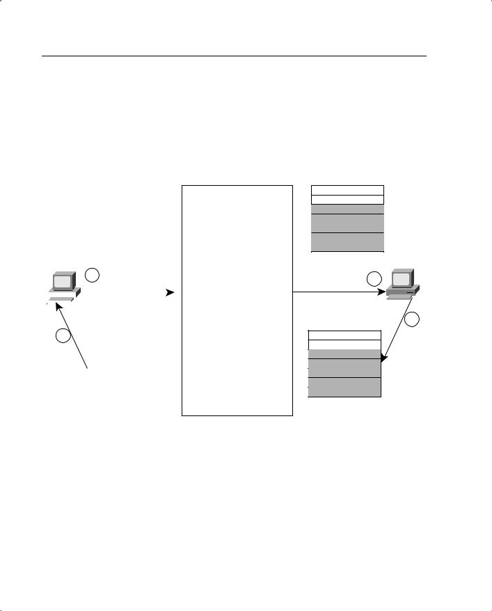
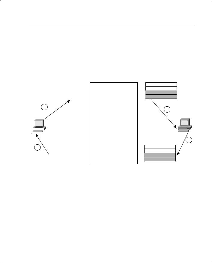
 (Src IP, Src Port, Dest IP, Dest
 Translation Check
152 Chapter 8: PIX Firewall
Stateful Inspection of Traffic Using the ASA
We have discussed in detail how the ASA works. This section looks at some of the basic rules the PIX Firewall uses to control access into a network. These rules also set up the basis for all other traffic flowing through the PIX.
PIX Firewall uses the following basic set of rules to determine how traffic flows through it:
•No packets can traverse the PIX Firewall without a translation, connection, and state.
•Outbound connections are allowed, except those specifically denied by access control lists. An outbound connection is one in which the originator or client is on a higher security interface than the receiver or server. The highest security interface is always the inside interface, and the lowest is the outside interface. Any perimeter interface can have security levels between the inside and outside values.
•Inbound connections or states are denied, except those specifically allowed. An inbound connection or state is one in which the originator or client is on a lower security interface or network than the receiver or server.
•All ICMP packets are denied unless they are specifically permitted. This includes echo replies to pings originated from the inside network.
•All attempts to circumvent the previous rules are dropped, and a message is sent to syslog.
PIX uses these rules to define a basic firewall setup for the traffic flowing through it. After this is done, you can set up more-specific constraints based on various other conditions to tighten or relax the security in certain areas. The rest of this section looks at some of the techniques for further defining the security role of the PIX Firewall.
Assigning Varying Security Levels to Interfaces
PIX Firewall allows varying security levels to be assigned to its various interfaces. This key technique allows for the implementation of a security policy calling for varying levels of security control in a network’s different segments. These segments are usually called security zones.
A PIX Firewall can have from two to ten interfaces. Each interface can be assigned a level from 0 to 100. A lower level number means that an interface belongs to a relatively lesssecure part of the network as compared to an interface that has a higher level number.
Typically, the interface connected to the public network has a 0 level assigned to it. This describes a very low level of security. The interface sitting on the private network has a security level of 100, meaning that it is the most secure. DMZ interfaces have security levels between 0 and 100. By default, traffic can flow freely from a high security level interface to a low security level interface, provided that a network address translation (xlate) is built for the traffic’s source IP addresses. PIX keeps track of the connections for this traffic and allows the return traffic through. However, for traffic to flow from a


Basic Features of the PIX Firewall 155
route information on its various interfaces. PIX can broadcast a default route only if it is configured to do so via RIP. In addition, PIX cannot propagate the RIP information learned from a network attached to one of its interfaces to a network attached to another of its interfaces. PIX does however support RIPv2’s security features.
Network Address Translation
PIX can perform NAT for packets traversing any two of its interfaces. PIX’s default behavior is to require NAT. This means that NAT must be set up for a connection state to be created, regardless of the level of the interface from which the packet originates. PIX allows NAT rules to be set up separately for various sets of interfaces. This allows flexibility in how NAT is deployed on the PIX. One method of NAT may be used for one pair of interfaces, and another may be used for another pair of interfaces. The most common use of NAT is when the private network behind the PIX uses an RFC 1918 space. PIX can convert the source addresses of the packets leaving this network into a globally routable address configured on it. PIX then maintains state information for this translation so that it can route the return traffic to the correct host on the internal network. NAT can also be used between two interfaces on the PIX, neither of which is on the public network, so they do not use a globally routable address space. In this case, NAT occurs from an RFC 1918 space to an RFC 1918 space. While the practical need for having this type of translation may be limited, PIX requires NAT to be setup in order to pass traffic between any two interfaces. PIX can do both one-to-one and one-to-many NAT. For a more detailed discussion of NAT’s security aspects, see Chapter 6, “Network Address Translation and Security.”
The PIX Firewall also provides static Port Address Translation (PAT). This capability can be used to send multiple inbound TCP or UDP services to different internal hosts through a single global address. The global address can be a unique address or a shared outbound PAT address or it can be shared with the external interface.
The PIX Firewall (in version 6.2 and later) also can do address translation for the source IP addresses of packets going from a low-security interface to a high-security interface. This functionality does not remove the need to have a static translation to be able to access the machines sitting on a higher security level from a lower security level.
Failover and Redundancy
Failover in PIX allows a standby system to take over the functionality of the primary system as soon as it fails. This changeover can be set up to be stateful, meaning that the connection information stored on the failing PIX is transferred to the PIX taking over. Before getting into a discussion of how failover takes place on the PIX Firewall, it is useful to define some of the terminology that the PIX uses for the failover functionality.

156 Chapter 8: PIX Firewall
Active Unit Versus Standby Unit
The active unit actively performs normal network functions. The standby unit only monitors, ready to take control should the active unit fail to perform.
Primary Unit Versus Secondary Unit
The failover cable has two ends, primary and secondary. The primary unit is determined by the unit that has the end of the failover cable marked “primary.” The secondary unit is connected to the end of the failover cable marked “secondary.”
System IP Address Versus Failover IP Address
The system IP address is the IP address of the primary unit (upon bootup). The failover IP address is the IP address of the secondary unit.
State information for stateful failover is communicated to the PIX taking over through an Ethernet cable joining the two PIXes. However, the actual detection of whether a unit has failed takes place via keepalives passed over a serial cable connected between the two PIXes (see note later on in the section on enhancements made in ver 6.2 of PIX). Both units in a failover pair communicate through the failover cable, which is a modified RS-232 serial link cable that transfers data at 117,760 baud (115 KB). The data provides the unit identification of primary or secondary, indicates the other unit’s power status, and serves as a communication link for various failover communications between the two units. For the failover to work correctly, the hardware, software, and configurations on the two PIXes need to be identical. It is simple enough to use commands on the PIX to synch the configurations of the two PIXes, but the hardware and software must be matched up manually. The two units send special failover hello packets to each other over all network interfaces and the failover cable every 15 seconds. The failover feature in PIX Firewall monitors failover communication, the other unit’s power status, and hello packets received at each interface. If two consecutive hello packets are not received within a time determined by the failover feature, failover starts testing the interfaces to determine which unit has failed, and it transfers active control to the standby unit. If a failure is due to a condition other than a loss of power on the other unit, the failover begins a series of tests to determine which unit failed. These tests are as follows:
•Link up/down test—This is a test of the network interface card. If an interface card is not plugged into an operational network, it is considered failed (for example, a switch failed due to a faulty port, or a cable is unplugged).
•Network activity test—This is a received network activity test. The unit counts all received packets for up to 5 seconds. If any packets are received during this interval, the interface is considered operational, and testing stops. If no traffic is received, the ARP test begins.

Basic Features of the PIX Firewall 157
•ARP test—The ARP test consists of reading the unit’s ARP cache for the ten most recently acquired entries. One at a time, the unit sends ARP requests to these
machines, attempting to stimulate network traffic. After each request, the unit counts all received traffic for up to 5 seconds. If traffic is received, the interface is considered operational. If no traffic is received, an ARP request is sent to the next machine. If at the end of the list no traffic has been received, the ping test begins.
•Broadcast ping test—The ping test consists of sending out a broadcast ping request. The unit then counts all received packets for up to 5 seconds. If any packets are received during this interval, the interface is considered operational, and testing stops. If no traffic is received, the testing starts again with the ARP test.
The purpose of these tests is to generate network traffic to determine which (if either) unit has failed. At the start of each test, each unit clears its received packet count for its interfaces. At the conclusion of each test, each unit looks to see if it has received any traffic. If it has, the interface is considered operational. If one unit receives traffic for a test and the other unit does not, the unit that received no traffic is considered failed. If neither unit has received traffic, go to the next test.
The PIX taking over assumes the IP addresses as well as the MAC addresses of the failed PIX, allowing for transparency for the hosts attached to the interfaces of the failed PIX. The unit that activates assumes the IP and MAC addresses of the previously active unit and begins accepting traffic. The new standby unit assumes the failover IP and MAC addresses of the unit that was previously the active unit. Because network devices see no change in these addresses, no ARP entries change or time out anywhere on the network.
In general, the following events can often cause a PIX Firewall to fail over to a backup:
•Running out of memory. PIX looks for out-of-memory errors for 15 consecutive minutes before it fails over.
•Power outage on the primary PIX, or a reboot.
•An interface’s going down for more than 30 seconds.
You can also force a failover manually by issuing the failover active command on the secondary PIX Firewall.
In case of a stateful failover, the following information is replicated from the primary PIX to the secondary PIX:
•The configuration
•TCP connection table, including timeout information for each connection
•Translation (xlate) table
•System up time; that is, the system clock is synchronized on both PIX Firewall units


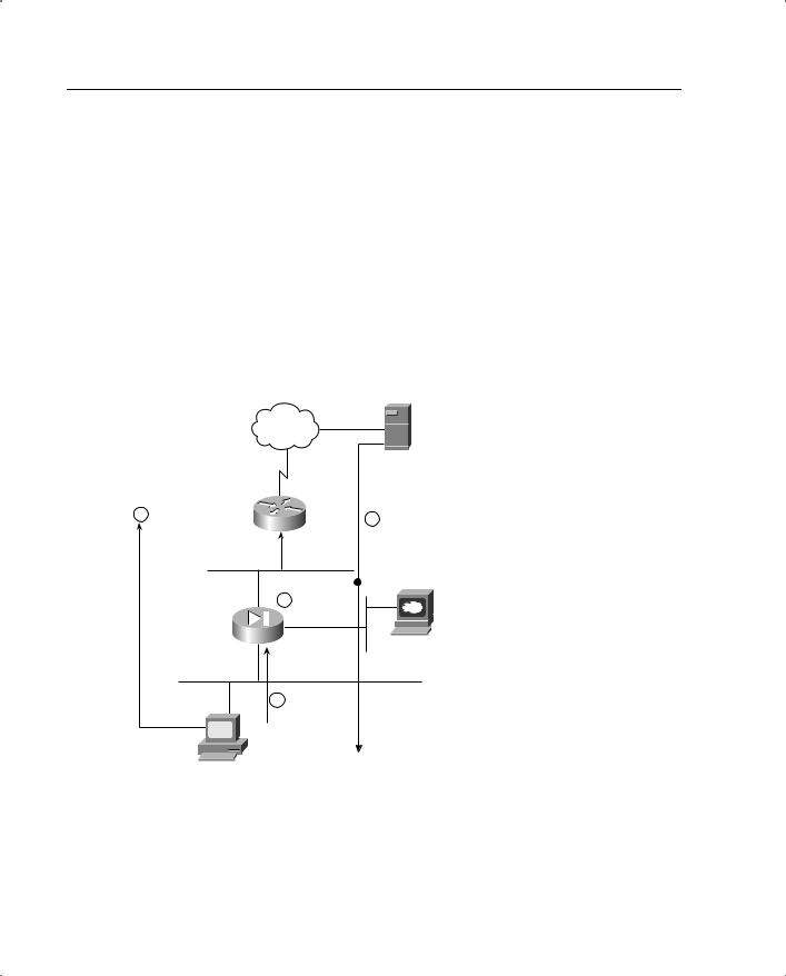
160 Chapter 8: PIX Firewall
An example of using the alias command in this manner occurs when hosts located on the inside network use an external DNS server to resolve the name of a server sitting on the PIX Firewall’s DMZ interface. The server is physically configured with an RFC 1918 address that is statically translated into a globally routable address on the PIX to allow access from the outside world. If a client on the private network tries to access the server and send a DNS request to the DNS server, the DNS server replies with the server’s globally routable address, not its RFC 1918 address. The PIX is set up to do aliasing such that when the client on the internal network sends a packet to the globally routable IP address of the server on the DMZ, the PIX translates the destination IP address to that of the server’s RFC 1918 address and forwards the packet to its DMZ interface. Another way to resolve this problem is to have separate internal and external DNS servers, but this is not always possible.
Figure 8-4 depicts how the alias feature can be used to deal with this scenario.
Figure 8-4 How the Alias Feature Does NAT on the Destination IP Addresses
Internet |
DNS Server (test.cisco.com = 150.1.1.1) |
1 DNS Request |
|
2 DNS Response = 150.1.1.1 |
|
for test.cisco.com |
|
||
4 |
PIX Changes |
|
|
the Destination |
Web Server (test.cisco.com = 192.168.1.1) |
||
Static (DMX Outside) |
Address to |
||
|
|||
192.168.1.1 |
|
||
150.1.1.1 192.168.1.1 |
|
||
|
|
||
255.255.255.255 |
|
|
3 Packet Sent to 150.1.1.1
End Host
“DNS Doctoring” by the Alias Feature
The PIX’s alias feature can also doctor or modify the responses, passing through the PIX Firewall, sent to a client by a DNS server. This is a very useful feature when an external DNS server is the only DNS server available to the clients sitting on the PIX’s inside network.
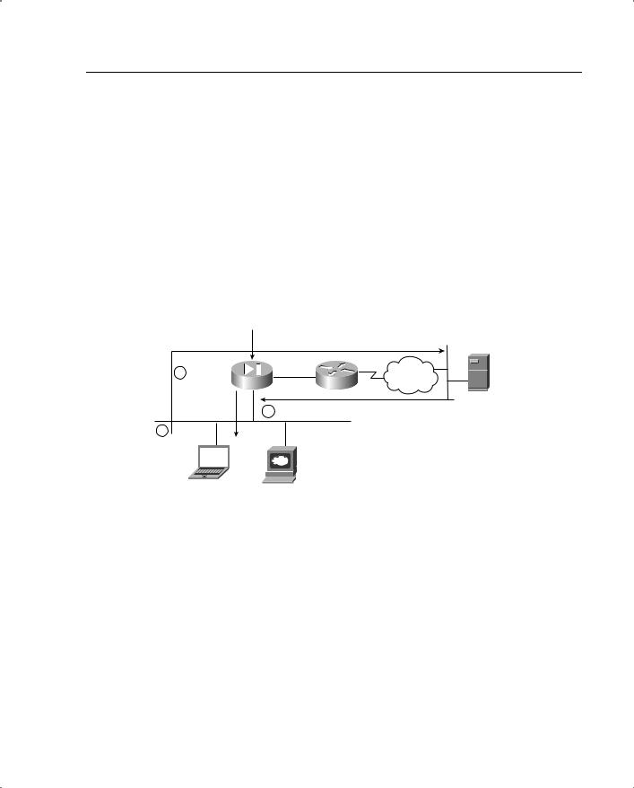


164 Chapter 8: PIX Firewall
buffer resources, the fragments are switched through the PIX port address translation mechanism based on the tagged information. It is not a requirement for the first fragment containing the port information to arrive first on the PIX Firewall. However, the PIX Firewall does not forward the packet to the next-hop box until all the packet’s fragments have arrived at it and have been verified and tagged with the transport information contained in the initial fragment.
NOTE ICMP packets are still reassembled in full rather than being virtually reassembled.
PIX also allows the use of the fragment command to allow various parameters for fragmentation to be configured. This is especially useful in environments where fragmentation for legitimate reasons is very likely. An example of such an environment is an NFS environment. See the PIX command reference for the 6.1 code for details on this command.
PIX Firewall versions before 5.1.4 required that the fragments be received in sequence, with the fragment containing the header arriving first. In Linux-based environments, this behavior can be catastrophic. Therefore, it should be disabled pending a review of the operating conditions of the servers and applications. The Linux OS, if it must fragment packets, has a habit of delivering them in reverse order. This is perfectly acceptable in TCP/IP, but the PIX with frag guard enabled used to drop any fragmented packets that arrived out of order, effectively dropping all fragmented traffic in a Linux environment. Similar problems occurred if PIX Firewall was used as a tunnel for FDDI packets between routers. Consequently, this requirement was removed from 5.1.4 code onward.
Mail Guard
The mail guard feature is used to make sure that only a minimal set of seven SMTP commands can be sent to a mail server sitting behind the PIX Firewall. This helps prevent attacks on the mail server. The seven commands from RFC 821 are HELO, MAIL, RCPT, DATA, RSET, NOOP, and QUIT. The PIX Firewall intercepts the rest of the commands, such as KILL and WIZ, and responds with an OK. This lulls an attacker using these commands into believing that the mail server is receiving these commands and acknowledging them.You enable this feature using the fixup protocol smtp 25 command in the newer PIX versions. The use of this command also alleviates the need for having a mail relay on the edge of the network.
Although this PIX feature is very useful in stopping certain types of SMTP attacks launched using a set of commands other than the seven just listed, this behavior can be very disruptive for certain mail server environments such as ones that use Microsoft Exchange, which uses ESMTP. Therefore, you should use this PIX feature with care and turn it off if absolutely necessary.

Advanced Features of the PIX Firewall 165
DNS Guard
DNS guard is a feature used in the PIX to stop DNS-based DoS attacks. DNS DoS attacks occur when an attacker poses as a DNS server to which a DNS resolution request has been sent and then floods the user requesting the DNS resolution with DNS responses. PIX mitigates these types of attacks by doing the following:
•PIX does not allow more than one DNS response from any DNS server.
•If a client queries more than one DNS server, as soon as PIX sees one of them respond to a DNS request, it closes the hole it opened (the access list hole plus the xlate) to allow responses from the other DNS servers.
Advanced Filtering
PIX Firewall has built-in traffic filtering features that can block certain types of traffic based on its content. ActiveX and Java applets are two kinds of traffic that can be stopped from reaching the private network via the PIX. Also, using software from Websense, PIX allows for more sophisticated filtering of content based on the types of websites being visited.
Websense runs separately from the PIX Firewall. It contains an extensive database of URLs arranged in various categories. PIX uses the Websense protocol to interact with the Websense server to find out if the URLs contained in the HTTP GET requests passing through it are allowed or not. The Websense server makes this decision based on the policy set on it by the administrator based on the site security policy. Using the Websense server provides the following three elements to the PIX Firewall setup:
•URL filtering allows the PIX Firewall to check outgoing URL requests against the policy defined on the Websense server.
•Username logging tracks the username, group, and domain name on the Websense server.
•Username lookup lets the PIX Firewall use the user authentication table to map the host’s IP address to the username.
Using the Websense server to filter malicious URL requests can be resource-intensive on a heavily loaded PIX. Although most of the heavy processing is carried out on the Websense server, the communication still needs to take place from within the PIX Firewall software. PIX gets around some of this slowness by building within itself a cache of URLs and the responses generated for them by the Websense server. This lets faster checks be carried out on the most frequently accessed URLs without needing to consult the Websense server. The size of this cache can be configured on the PIX Firewall. However, using the cache feature does bypass one useful feature of the Websense server: URL logging. URL logging allows the Websense server to log various types of information about the URL and the user associated with it. With caching enabled, this feature is no longer in use.

166 Chapter 8: PIX Firewall
PIX deals with the Java applets being downloaded within an HTML page by going into the page’s HTML code and commenting out the Java applet source code. This way, the end user still receives the web page but does not get the Java applet that is embedded in it.
Multimedia Support
Multimedia support through a firewall is tricky for two main reasons.
The first is that a firewall often does NAT for the RFC 1918 addresses sitting on the private network behind it. Because many multimedia applications embed IP addresses in some of their payload packets, the firewall has to dig into the packet and change these IP addresses as well in accordance with the NAT rules set up on it.
The second reason why supporting multimedia traffic is often difficult is that many multimedia applications, instead of using fixed and predetermined port numbers, actually negotiate the port numbers that are to be used for the data to be transferred. This creates problems because the firewall must create address translation entries for these ports. It also causes problems because the firewall often must take into account the fact that as soon as the multimedia client sitting behind it has initiated a connection to a multimedia server, the server might try to establish an independent connection back to the client on the negotiated port. The firewall must open a hole for that connection to take place based on the negotiation that took place between the client and the server.
Figure 8-7 illustrates the two problems just discussed.
A good example of one such implementation where PIX has to take care of a complicated transaction between a client and a server is the implementation of VoIP using H.323 with GK (Gate Keeper) or a proxy server with SIP. VoIP deployments usually involve many endpoints, and customers often have limited IP addresses for each of these endpoints, resulting in a need to do PAT.Adding support for PAT with H.323 and SIP allows customers to expand their network address space using a single global address.
To support PAT with the H.323 or SIP fixup, first the correct PAT for the embedded IP/port in the H.323/SIP message needs to be found and the embedded IP address must be changed in the payload. Then the correct media connections based on the ports that were negotiated during the signaling need to be opened. If a PAT does not exist, one needs to be created.
A PAT does not exist if there has been no outbound traffic from that particular host on a particular port. Or perhaps a PAT did exist but was torn down because it expired or was removed by the user. This leads to another problem where the clients register with either the proxy server (for SIP) or the GK (for H.323). The registrations tell the proxy server or GK that the client can be reached at a certain IP address/port. These registrations last for a specific timeout value determined by both client and server. This means that PIX must sniff this timeout value from the negotiation between the client and the server and modify the dynamic PAT timeout value on itself to match this VOIP timeout value.
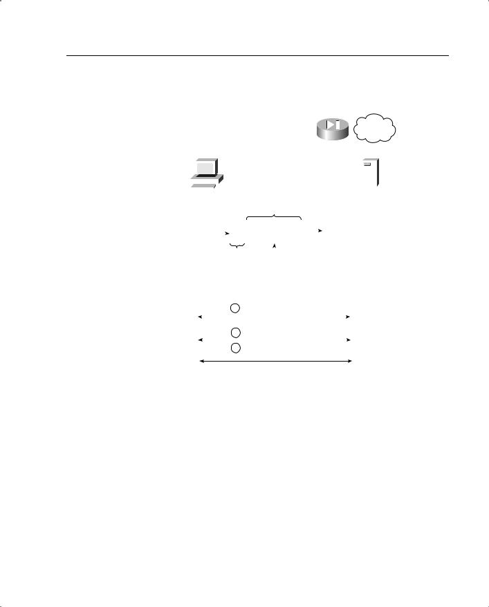
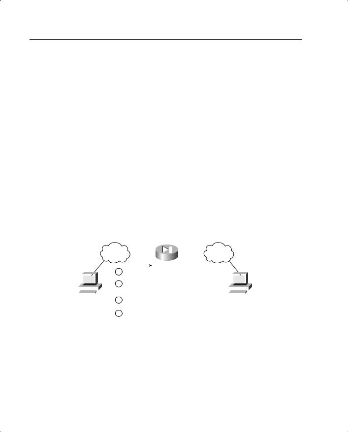
168 Chapter 8: PIX Firewall
normal. If there is no reverse-path route on the same interface from which the packet was received, this might mean that the source address was modified or spoofed. Also if URPF simply does not find a reverse path for the packet, the packet is dropped.
URPF in PIX is implemented as follows:
•ICMP packets that have no session have each of their packets checked by URPF.
•UDP and TCP have sessions, so the initial packet requires a reverse-route lookup. Subsequent packets arriving during the session are checked using an existing state maintained as part of the session. Noninitial packets are checked to ensure that they arrive on the same interface used by the initial packet.
For URPF to work correctly, the PIX needs to have a route to the source IP address. If that route does not exist, there is no way for the PIX to verify that the packet was received from a source that does not have the right to send packets with that specific source IP address. Therefore, before using this command, you should add a static route command for every network that can be accessed on the interfaces you want to protect or you should set up proper RIP routing to gather this information. This command should be enabled only if routing is fully specified. PIX Firewall stops traffic on the interface specified if routing is not in place.
Figure 8-8 shows how URPF works on the PIX Firewall.
Figure 8-8 URPF Feature in PIX
|
|
|
|
|
|
|
Route Inside 10.0.0.0 255.0.0.0 |
|
|
|
|
|
|
|
|
|
|
|
|
|
Internal |
|
Public |
|
|
|
|
|
|
||||
|
|
|
|
Network |
|
|
|
Network |
||||||||
|
|
|
|
|
|
|
|
|
|
|
|
|
|
|||
|
|
|
|
1 |
Packet Arrives at PIX Inside Interface From 10.1.1.1. |
|
|
|
|
|
|
|||||
|
|
|
|
2 |
|
PIX Has a Return Route To it Through the Interface on |
|
|
|
|
|
|
||||
|
|
|
|
|
Which the Packet Was Received. PIX Allows the |
|
|
|
|
|
|
|
|
|||
|
|
|
|
|
|
|
|
|
|
|
|
|
||||
|
|
|
|
|
|
|
Packet To Be Processes Further. |
|
|
|
|
|
|
|
|
|
|
|
|
|
|
|
|
|
|
|
|
|
|
|
|
|
|
10.1.1.1 |
|
3 |
|
Packet Arrives at the Inside Interface With a Source |
160.1.1.1 |
|
|
|||||||||
|
|
|
|
|
|
|
|
|
|
|
||||||
|
|
|
|
|
|
|
Address of 160.1.1.1 (Spoofed). |
|
|
|
|
|
|
|
|
|
4PIX Drops the Packet Since the Best Path to 160.1.1.1
Is Through Its Outside Interface and Not the Inside Interface.
Protocol Fixup
PIX uses protocol fixup to deal with special behaviors, exhibited by certain protocols, that cannot be dealt with by the ASA in its normal mode of operation. You saw an example of this in the section “Multimedia Support”. Another example of such protocol behavior is exhibited by FTP. Active FTP requires that after the client has initiated a connection to the server (a command session), the server should connect to the client (a data session) using a different port number combination than the one the client used to initiate the connection.

Advanced Features of the PIX Firewall 169
The server initiates this connection on its own rather than respond back to the initial connection the client has opened. Assuming that the client is sitting behind a PIX firewall, this requires the PIX to find out the new port number on which the server would connect to the client. PIX finds out this port by listening to the initial conversation between the client and the server taking place on the command session connection initiated by the client. Then the PIX sets up a translation if one is required and opens a hole in the firewall for the packets to go through to the client sitting on the inside. This requires special handling and is called ‘ftp protocol fixup’. The fixup protocol command allows the PIX administrator to change the port number that the PIX looks for to start this special handling procedures. For example, using the fixup protocol ftp 2021 command, PIX can be forced to monitor port 2021 to tell it to start using the special ftp fixup procedures. Please note that Passive FTP requires the client to initiate the command connection as well as the subsequent data connection.
This eliminates the need for the firewall to be aware of the ftp negotiations taking place and the subsequent special handling.
Other protocols supported by the PIX fixup are HTTP, SMTP, RSH, SQLNET, and H.323.
Miscellaneous sysopt Commands
sysopt commands are used to turn on some system features that are used for some very specific network behaviors. These commands allow the PIX to modify its behavior to respond to a unique set of circumstances, such as issues on the network with the path MTU or devices that do not follow the normal protocol sequences.
Examples of some of the most commonly used sysopt commands are provided in the following sections.
sysopt connection timewait Command
The sysopt connection timewait command is necessary to cater to end host applications whose default TCP terminating sequence is a simultaneous close instead of the normal shutdown sequence (see RFC 793). In a simultaneous close, both ends of the transaction initiate the closing sequence, as opposed to the normal sequence in which one end closes and the other end acknowledges before initiating its own closing sequence.
The default behavior of the PIX Firewall is to track the normal shutdown sequence and release the connection after two FINs and the acknowledgment of the last FIN segment. This quick release heuristic lets the PIX Firewall sustain a high connection rate.
When simultaneous close occurs two FINs are sent across the PIX, one from each end of the connection. In order to close the connections on both ends of the TCP connection using simultaneous close, both ends must receive acknowledgements of the FINs they have sent out. However, the PIX thinks that the closing sequence is a normal TCP close sequence rather than a simultaneous close sequence. So after seeing the two FINs and then the

170 Chapter 8: PIX Firewall
acknowledgement from one end, it closes out the connection on the firewall as it would if it were a normal close sequence. However, in this case, one end of the TCP connection is left waiting, in the CLOSING state, for a response to the FIN it has sent out. Many sockets in the CLOSING state can degrade an end host’s performance. For instance, some WinSock mainframe clients are known to exhibit this behavior and degrade the performance of the mainframe server. Old versions of HP/UX are also susceptible to this behavior. Enabling the sysopt connection timewait command creates a quiet-time window for the abnormal close-down sequence to complete. What this means is that after the PIX has seen what is considers to be the close of a connection, it waits 15 seconds before it closes out the connections. This wait time allows simultaneously closing connections to close on both ends properly since hopefully the final ACK gets transmitted during the 15 seconds of grace period. Please note however, that the PIX waits 15 seconds for all connection closes once this feature has been turned on, irrespective of whether they are normal closes or simultaneous closes. This can result in significant degradation of performance in environments where there are a lot of new connections being created and a lot of old connections being terminated in large quantities. This is the reason this feature is turned off by default.
sysopt noproxyarp Command
The sysopt noproxyarp command allows you to disable proxy ARPs on a PIX Firewall interface.
Proxy ARP in PIX is used mainly when the PIX wants to receive packets destined for a certain IP address on one of its interfaces and forward them to another interface connected to it. An example of this is the PIX proxy ARPing for the addresses contained in PIX’s global pool of NAT addresses for the hosts sitting on the inside private network behind the PIX, provided that an xlate has been created by traffic originating from the inside network. Upon receiving the packets destined for these addresses, the PIX forwards them to the inside network after performing the normal checks and translations.
In general, while Proxy ARPing a perfectly legitimate feature of networking, Proxy ARP should be best thought of as a temporary transition mechanism. Its use should not be encouraged as part of a stable solution. A number of potential problems are associated with its use, including hosts’ inability to fall back to alternative routes if a network component fails, and the possibility of race conditions and bizarre traffic patterns if the bridged and routed network segments are not clearly delineated.
Using specific routes and default gateway routes eliminates the need for end hosts to use proxy ARPing as a mechanism for routing packets.
The sysopt noproxyarp command is generally used in situations where it is inappropriate for the PIX to respond with proxy ARPing due to network misconfigurations or bugs. An example of such a situation is shown in Figure 8-9.
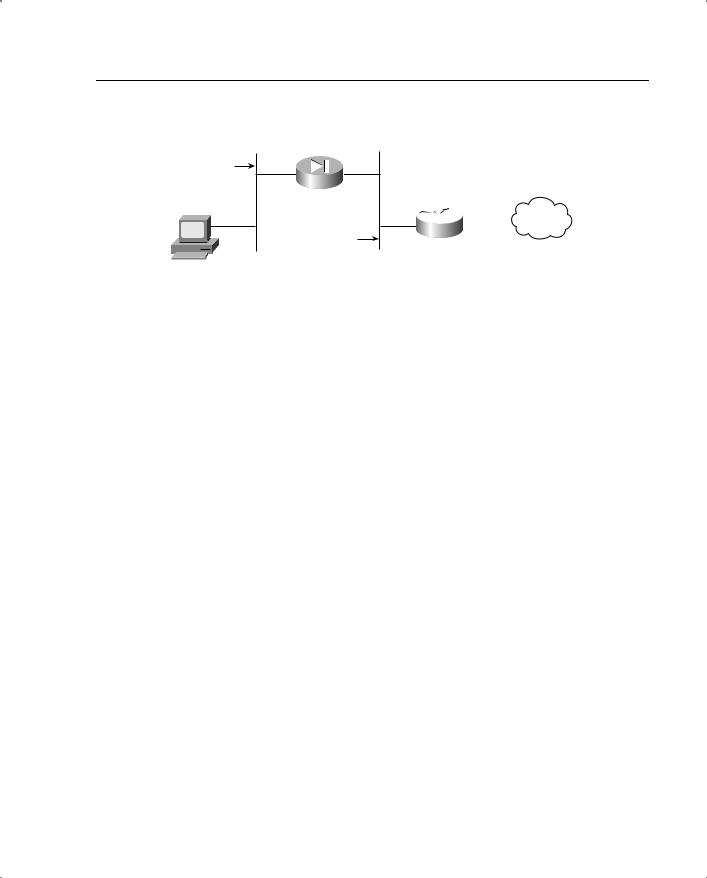
Advanced Features of the PIX Firewall 171
Figure 8-9 sysopt nonproxyarp Feature Usage
Inside
Network
 Internet
Outside
Network
Host A
The PIX in this scenario is set up with a nat (inside) 0 0 0 command, which implies that PIX will not translate any of the IP addresses on the inside network. Due to how the nat 0 command is designed, the PIX starts to proxy ARP on the outside interface for any and all addresses upon being configured in this manner. Consequently, if host A wants to access the Internet and sends an ARP and the PIX proxy ARPs before the router can respond, host A would be sending traffic destined for the Internet to the PIX, which is incorrect routing. The way around this scenario is to turn off proxy ARP on the PIX. However, after you do this, the PIX stops ARPing for all addresses, even the ones for which it should ARP. Now the router needs to be set up with routes for the inside network behind the PIX so that it does not have to rely on the PIX proxy ARPing for that network. This situation would never have arisen if the nat 0 command were set up with specific IP address ranges contained on the inside network. The noproxyarp command allows the system administrator to get over this mix of misconfiguration and product shortcoming.
sysopt connection tcpmss Command
The sysopt connection tcpmss command forces proxy TCP connections to have a maximum segment size no greater than a configurable number of bytes. This command requests that each side of a TCP connection not send a packet of a size greater than x bytes. The negotiation for mss is done during the initial TCP connection establishment.
The number of bytes can be a minimum of 28 and any maximum number. You can disable this feature by setting this value to 0. By default, the PIX Firewall sets 1380 bytes as the sysopt connection tcpmss even though this command does not appear in the default configuration. The calculation for setting the TCP maximum segment size to 1380 bytes is as follows:
1380 data + 20 TCP + 20 IP + 24 AH + 24 ESP_CIPHER + 12 ESP_AUTH + 20 IP = 1500 bytes
1500 bytes is the MTU for Ethernet connections. It is recommended that the default value of 1380 bytes be used for Ethernet and mixed Ethernet and Token Ring environments. If the PIX Firewall has all Token Ring interfaces, the MTU can be set to 4056. However, if even one link along the path through the network is not a Token Ring, setting the number of bytes
172 Chapter 8: PIX Firewall
to such a high value might cause poor throughput. In its 1380-byte default value, this command increases throughput of the sysopt security fragguard command.
Because the TCP maximum segment size is the maximum size that an end host can inject into the network at one time (see RFC 793 for more information on the TCP protocol), the tcpmss command allows for improved performance in network environments where the path MTU discovery is not taking place properly because an end host is not responding to requests to lower its MTU or a firewall is sitting next to the end host dropping the ICMP packets being sent to the end host to request a reduction in its MTU. The tcpmss command forces the size of the TCP segments to a small value during TCP’s initialization sequence, thereby eliminating the need for ICMP type 3 code 4 messages to be used to try and reduce the MTU. Also, most end hosts, even the ones that do not respond to ICMP messages requesting a decrease in packet size, do respond to tcpmss negotiation favorably.
Multicast Support
PIX Firewall allows multicast traffic to be passed through it (in version 6.2 and later). PIX Firewall allows statically configurable multicast routes or the use of an IGMP helper address for forwarding IGMP reports and leave announcements. PIX also allows filtering to be done on the multicast traffic passing through the PIX.
Figure 8-10 shows how the PIX Firewall acting as a proxy agent forwards IGMP report and leave messages to a multicast-enabled router, which updates PIM based on these messages. The result is that the end hosts on the internal network can receive the multicast video traffic from the server on the Internet.
Figure 8-11 shows another scenario in which the multicast server is sitting behind the PIX Firewall. In this case, the PIX Firewall’s role is to forward the multicast traffic received from the server sitting behind it to a multicast router. The router then uses PIM-based mechanisms to forward the traffic for distribution to end hosts listening for this traffic.
The following summarizes the PIX Firewall’s multicast support:
•Access list filters can be applied to multicast traffic to permit or deny specific protocols and ports.
•NAT and PAT can be performed on the multicast packet source addresses only.
•Multicast data packets with destination addresses in the 224.0.0.0/24 address range are not forwarded. However, everything else in the 224.0.0.0/8 address range is forwarded.
•IGMP packets for address groups within the 224.0.0.0 to 224.0.0.255 range are not forwarded, because these addresses are reserved for protocol use.
•NAT is not performed on IGMP packets. When IGMP forwarding is configured, the PIX Firewall forwards the IGMP packets (report and leave) with the IP address of the helper interface as the source IP address.
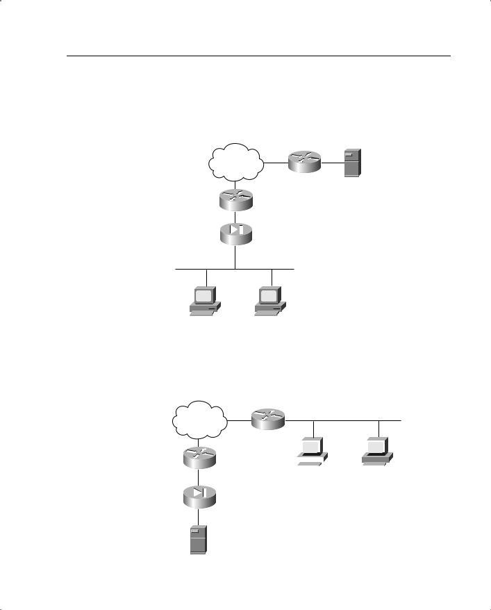


Advanced Features of the PIX Firewall 175
based on the TCP flags, such as SYN=0 or 1 or ACK=0 or 1, they cannot test the first fragment for this information. Also, since most network devices do not do reassembly of packets passing through them, they do not check the rest of the fragments and let them pass through. This way, an attacker can get an illegitimate packet through to an end host sitting behind these devices.
Newer versions of PIX protect against this type of an attack through the use of virtual reassembly. Virtual re-assembly insures that the flag information whether it is in the first fragment or other fragments is looked at before the packet is forwarded.
Older versions of PIX, protects against this type of attack by using the following algorithm to test packets:
IF FO=1 and PROTOCOL=TCP THEN drop packet
FO=1 refers to the second fragment of the tiny fragment attack packet. FO is 1 only if the first fragment (the initial fragment) is so small that the second fragment has an offset of only eight octets, or FO=1. This forces the PIX to drop this fragment, thereby stopping any reassembly at the end host because now one of the IP packet fragments is missing. The “interesting” fields (meaning the fields containing the port information and the flags of the common transport protocols, except TCP) lie in the first eight octets of the transport header, so it isn’t possible to push them into a nonzero offset fragment. So the threat of this attack does not exist for these protocols.
Overlapping Fragment Attack
The overlapping fragment attack makes use of the conditions set out in RFC 791 for reassembly of IP fragments for end hosts. It describes a reassembly algorithm that results in new fragments overwriting any overlapped portions of previously received fragments. This behavior allows an attacker to send the TCP flags in two fragments of the IP packet. The first fragment contains flags that are allowed to pass through the configured access list (SYN=0). However, the same flags are repeated in the second fragment and this time are set to a different value (SYN=1). The access list allows the first fragment to go through because it matches the requirements. The access list does not run any tests on the remaining fragments. Therefore, when an end host receives the two fragments, it overwrites the first fragment’s flags with the ones in the second fragment, defeating the purpose of the access list. This type of attack can be stopped using the same algorithm used for the tiny fragment attack. For all the relevant TCP header information to be contained in the first fragment and to not overlap with another fragment, the second fragment’s minimum offset must be 2 (meaning that the first fragment contains at least 16 octets). Therefore, dropping fragments with FO=1, PIX eliminates the possibility of this type of attack as well.
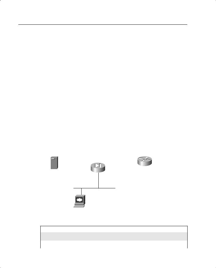


180 Chapter 8: PIX Firewall
Example 8-1 PIX Firewall with Three Interfaces Residing on the DMZ Interface (Continued)
!DMZ network is considered somewhat safe
rip dmz passive version 2
!The route outside command below is a default route. If the PIX is unable to !determine the interface to which it must forward a packet using its ARP table, it !must use the route table to find out what to do. The interface name in the route !commands specifies the interface on which the PIX must send an ARP request for !the IP address listed as the default gateway if it does not already have it in its !ARP cache. Once the PIX has the MAC address of the IP address specified in the !route command, it forwards the packet on the interface specified in the route !command using this MAC address as the destination. The number 1 at the end !specifies the metric for the route. A metric is used to choose the better route if !more than one route is configured for the same destination.
route outside 0.0.0.0 0.0.0.0 209.165.201.1 1
!The timeout command below is used to define the time it will take a NAT !translation created through the PIX to be removed after it has not been used for !the time specified in this command. The value configured is 1 hour
timeout xlate 1:00:00
!The timeout command below defines how long the PIX will allow a connection to !remain idle before it removes the entry. Please note that although the TCP !protocol itself does not have a timeout built into it, the PIX firewall does !implement its own timeout for such connections. The value configured here is 1 !hour. The half-closed time is used to specify how long PIX will allow a half- !closed connection to linger. This is an important timer to take care of !applications that get killed without getting the chance to close their TCP !connections entirely. The UDP timer is for UDP connections through the PIX, as !discussed in the ASA section on UDP
timeout conn 1:00:00 half-closed 0:10:00 udp 0:02:00 rpc 0:10:00 h323 0:05:00
sip 0:30:00 sip_media 0:02:00
!The timer that follows defines how long the PIX caches a user's !authentication and authorization credentials. The absolute keyword runs the !times continuously, irrespective of whether the user is idle
timeout uauth 0:05:00 absolute
!The sysopt commands below turn on some of the security features that are !desirable for specific network environments. Please see the discussion in the !sections on sysopt commands and the x guard features for more details
sysopt connection timewait sysopt connection tcpmss sysopt security fragguard

Case Studies 181
Example 8-1 PIX Firewall with Three Interfaces Residing on the DMZ Interface (Continued)
!The commands that follow are used to specify SNMP information on the PIX. The !SNMP community string is a shared secret among the SNMP management station and !the network nodes being managed. PIX Firewall uses the key to determine if the !incoming SNMP request is valid. The SNMP server host is the IP address of the SNMP !management station to which traps should be sent and/or from which the SNMP !requests come.
snmp-server community saadatmalik123456789
snmp-server location Building 42, Sector 54
snmp-server contact Saadat Malik
snmp-server host inside 10.0.0.199
!The commands that follow are used to define the MTU of the interface connected !to the PIX. PIX fragments any IP datagrams larger than 1500 bytes
mtu outside 1500 mtu inside 1500 mtu dmz 1500
!The telnet commands below specify the IP address 10.0.0.93 on the inside network !from which telnetting to the PIX is allowed. Also specified is the timeout in !minutes for idle Telnet sessions to the PIX itself (not to devices behind the PIX !or elsewhere)
telnet 10.0.0.93 inside telnet timeout 5
!The terminal width command specifies the number of characters displayed on one !line when looking at output on the PIX
terminal width 80
This case study not only gave you an overview of one of the most commonly used PIX configurations but also reviewed the most common commands in the PIX setup. Larger PIX setups, meaning ones involving more than just the three interfaces, are done using configurations similar to the configuration in Example 8-1.
PIX Set up for Failover to a Secondary Device
PIX failover, as discussed in this and the preceding chapters, is one of the most important characteristics a firewall can have. Failover capabilities allow a network to maintain high availability faced with device failures. For failover to work smoothly, it is important to have the two PIXes sharing the responsibilities of the primary and secondary failover configured correctly before the failure occurs.
This case study shows how a primary PIX Firewall is configured to fail over to a secondary unit. Because at any time, depending on whether a PIX has failed, either the primary or the
182 Chapter 8: PIX Firewall
secondary PIX might be passing traffic, the terms active and standby are used to designate which PIX is passing the traffic.
Here are some things to keep in mind when setting up PIX Firewall failover:
•Hardware/software—Both the PIXes must have the same hardware and software.
•Interface connections—All the interfaces of the two PIXes must be connected to each other in some fashion, even if they are not in use and are in a shutdown state.
•Standby PIX—The standby PIX must not be configured independently. It must be write-erased and configured using the write standby command on the primary PIX.
•Stateful failure—If stateful failover is desired, one interface on each of the two PIXes must be sacrificed and used to connect the two PIXes via an Ethernet cable for this functionality to take place. This cable is in addition to the normal serial cable used to carry the heartbeat between the two devices (see the preceding failover discussion for a more detailed analysis of how this works). If a crossover cable is used to connect the stateful failover interfaces, a failure of the failover interface does not force a failover of the PIX, because the failover interfaces on both boxes go down.
•show failover—This command can be used to check the status of the primary or secondary device. This command provides information on which PIX is in active mode and which is in standby mode.
Figure 8-13 shows the network topology for this case study.
Figure 8-13 Network Topology for This Case Study
Internet
PMT Global
209.165.201.3 |
|
|
209.165.201.4 |
|
|
|
|
|
Static Global |
|
Hub |
PIX Firewall |
|
PIX Firewall |
|
209.165.201.5 |
|
||
Primary Unit |
|
outside |
Secondary Unit |
209.165.201.1 |
|
Failover |
209.165.201.2 |
|
192.168.254.1 |
192.166.254.2 |
|
|
192.168.253.1 |
Unused |
192.166.253.2 |
192.168.2.1 |
|
Inside |
192.168.2.2 |
|
|
|
Hub |
|
|
|
192.168.2.3 |
Web Server


184 Chapter 8: PIX Firewall
Example 8-2 Configuration of the Primary PIX Device (Continued)
failover ip address failover 192.168.254.2 failover ip address unused 192.168.253.2
!The failover link command specifies which interface will be used to carry the !state information to the standby PIX in case of a failover
failover link failover failover poll 15
arp timeout 14400
global (outside) 1 209.165.201.3 netmask 255.255.255.224 nat (inside) 1 0.0.0.0 0.0.0.0 0 0
static (inside,outside) 209.165.201.5 192.168.2.5 netmask 255.255.255.255 0 0 access-list acl_out permit tcp any 209.165.201.5 eq 80
access-list acl_out permit icmp any any access-group acl_out in interface outside
no rip outside passive no rip outside default no rip inside passive no rip inside default no rip failover passive no rip failover default
route outside 0.0.0.0 0.0.0.0 209.165.201.4 1 timeout xlate 1:00:00
timeout conn 1:00:00 half-closed 0:10:00
udp 0:02:00 rpc 0:10:00 h323 0:05:00
sip 0:30:00 sip_media 0:02:00 telnet timeout 5
terminal width 80
PIX Set up to Use the alias Command for a Server Sitting on the DMZ
This case study shows a way of using the alias command. This command is set up so that it can deliver the results discussed in the section “NAT on the Destination IP Addresses.” Example 8-3 provides a complete configuration for setting up the PIX Firewall to use the alias feature to achieve this result.
Consider a web server. If the web server and the client trying to access it are on the same PIX interface, the normal way of configuring the alias command (alias <Name of interface on which the server and client are located> <RFC 1918 address of the server> <Statically translated address of the server>) works fine. The alias command doctors the DNS server response for the name of the web server such that the client trying to connect to the server uses its private IP address to connect to it.
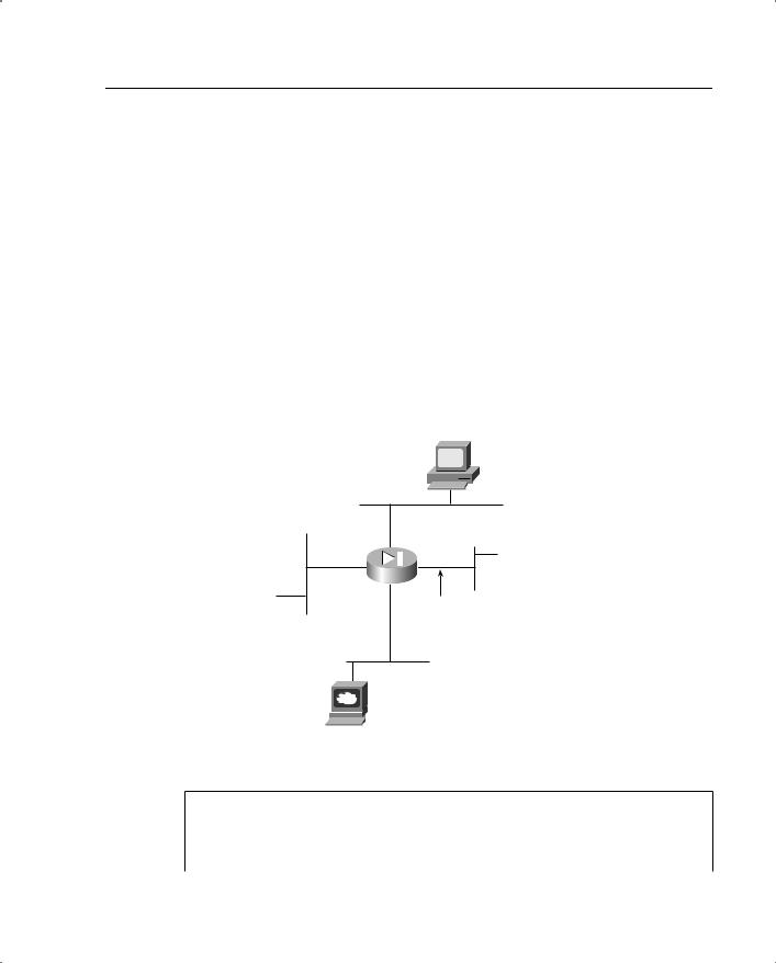

186 Chapter 8: PIX Firewall
Example 8-3 Configuring the PIX Firewall to Use the Alias Feature (Continued)
nameif ethernet3 intf3 security15 nameif ethernet4 intf4 security20 nameif ethernet5 intf5 security25
enable password 8Ry2YjIyt7RRXU24 encrypted passwd 2KFQnbNIdI.2KYOU encrypted
hostname pixfirewall names
!The access list that follows is used to allow access to the web server
access-list 101 permit tcp any host 172.17.241.250 eq www access-list 101 permit icmp any any
no pager logging on
no logging timestamp no logging standby
logging console emergencies no logging monitor
no logging buffered no logging trap
no logging history logging facility 20 logging queue 512
interface ethernet0 10full interface ethernet1 10full interface ethernet2 10full interface ethernet3 10full interface ethernet4 auto shutdown interface ethernet5 auto shutdown mtu outside 1500
mtu inside 1500 mtu intf2 1500 mtu intf3 1500 mtu intf4 1500 mtu intf5 1500
ip address outside 172.17.241.155 255.255.255.0 ip address inside 192.168.5.1 255.255.255.0
ip address intf2 192.168.10.1 255.255.255.0 ip address intf3 10.51.8.1 255.0.0.0
ip address intf4 127.0.0.1 255.255.255.255 ip address intf5 127.0.0.1 255.255.255.255
arp timeout 14400
!The command below sets up a global pool of one address for doing port address !translation. The IP address used is the IP address of the outside interface !itself. This is another way of defining a global pool of addresses.
global (outside) 1 interface
global (intf2) 1 192.168.5.101-192.168.5.200 nat (inside) 1 192.168.5.0 255.255.255.0 0 0 nat (intf3) 1 10.51.8.1 255.255.255.0 0 0


190 Chapter 8: PIX Firewall
Example 8-4 How PIX Is Set up to Do Authorization and Authentication (Continued)
no failover
failover timeout 0:00:00 failover poll 15
failover ip address outside 0.0.0.0 failover ip address inside 0.0.0.0 arp timeout 14400
global (outside) 1 99.99.99.10-99.99.99.20 netmask 255.255.255.0 nat (inside) 1 172.18.124.0 255.255.255.0 0 0
static (inside,outside) 99.99.99.99 172.18.124.114 netmask 255.255.255.255 0 0
access-list 110 permit tcp any 99.99.99.99 eq www access-list 110 permit tcp any 99.99.99.99 eq ftp access-list 110 permit tcp any 99.99.99.99 eq telnet route inside 0.0.0.0 0.0.0.0 172.18.124.1 1
timeout xlate 3:00:00
timeout conn 1:00:00 half-closed 0:10:00 udp 0:02:00 rpc 0:10:00 h323 0:05:00 si p 0:30:00 sip_media 0:02:00
timeout uauth 0:05:00 absolute
!
!The commands that follow are used to define server groups. The server group is !identified by the group tag, in this case AuthInbound and AuthOutbound. This !group tag is used to bind authentication and authorization commands to an AAA !server. Please note that we are not using the two server groups defined by !default in PIX, TACACS+, and RADIUS, but instead are defining our own, called !AuthInbound and AuthOutbound.
aaa-server TACACS+ protocol tacacs+ aaa-server RADIUS protocol radius
!The name of the first server group is defined in the command that follows
aaa-server AuthInbound protocol tacacs+
!The server group name is bound to the actual IP address of the AAA server in the !command below. The server key, cisco, is also defined
aaa-server AuthInbound (inside) host 172.18.124.111 cisco timeout 5
!Another server group is defined in the lines that follow because the intent is to !authenticate outbound connections using RADIUS rather than TACACS+
aaa-server AuthOutbound |
protocol radius |
aaa-server AuthOutbound |
(inside) host 172.18.124.111 cisco timeout 5 |
! |
|
!The first two commands |
that follow define what traffic is subject to |
!authentication via the |
server groups defined above. The AAA authorization command |
!turns on authorization |
for the traffic matching access list 101. Please note that |
!a user needs to be authenticated before authorization can take place. From |
|
!version 6.2, PIX allows per-user access lists to be downloaded from a RADIUS |
|
!server. Please see the |
chapter on AAA authorization for more details on how to |
!set up a user profile for this to happen.

Case Studies 191
Example 8-4 How PIX Is Set up to Do Authorization and Authentication (Continued)
aaa authentication match 101 outside AuthInbound aaa authentication match 101 inside AuthOutbound aaa authorization match 101 outside AuthInbound
no snmp-server location no snmp-server contact
snmp-server community public no snmp-server enable traps floodguard enable
no sysopt route dnat isakmp identity hostname telnet timeout 5
ssh timeout 5 terminal width 80
: end
The PIX saves the credentials of an authenticated user in a data structure known as uauth. The user can access resources through the PIX until either the idle timer or the absolute timer of uauth expires. After that, the user has to authenticate again to access the resources sitting behind the PIX.
Scaling PIX Configurations Using Object Groups and Turbo ACLs
Object groups (introduced in PIX 6.2) are a very useful mechanism for controlling the size of the PIX configurations and avoiding inputting redundant information in the PIX. Object grouping provides a way to reduce the number of access rules required to describe complex security policies. Object groups allow two main things to happen:
•Group several hosts that have similar access requirements such that a single access rule can be applied to all of them, rather than creating a separate rule for each host. This also helps make the configuration more meaningful and easily comparable to the network access policy.
•Group several services or protocols so that they can be applied to a range of hosts at the same time. This again avoids the need to create a separate rule for each host that needs to use these services.
TurboACL is a feature introduced with PIX Firewall version 6.2 that improves the average search time for access control lists containing a large number of entries. The TurboACL feature causes the PIX Firewall to compile tables forACLs; this improves searching of long ACLs. If anACL contains more than 19 entries and is set up for turbo access list compilation, PIX compiles the access list for faster processing. This is a useful feature to have in environments that require a large number of access lists to be set up.
192 Chapter 8: PIX Firewall
Example 8-5 describes how object groups and Turbo ACLs are used. The implementation of LAN failover, meaning stateful failover using LAN instead of the serial cable, is also discussed. This feature allows the distance limitations between the primary and secondary PIX to be overcome among other things.
Figure 8-16 shows the network setup via the configuration.
Figure 8-16 Network Topology for This Case Study
Internet
Ethernet0
Ethernet 2 |
Ethernet 3 |
10.0.2.210.0.1.2
Ethernet1
10.1.1.1
|
|
|
|
|
|
|
|
|
|
|
|
|
|
10.1.1.10 |
10.1.1.11 |
10.1.1.20 |
10.1.1.30 |
|
|||||||||
|
|
|
|
|
|
|
|
|
|
|
|
|
|
|
|
|
|
|
|
|
|
|
|
|
|
|
|
|
|
|
|
|
|
|
|
|
|
|
|
|
|
|
|
|
|
|
|
|
|
|
|
|
|
|
|
|
|
|
|
|
|
|
|
|
|
|
|
|
|
|
|
|
|
|
|
|
|
|
|
|
|
|
|
World Wide Web |
World Wide Web |
World Wide Web |
World Wide Web |
& |
& |
& |
& |
FTP Server |
FTP Server |
SMTP Server |
SMTP Server |
Example 8-5 How Object Groups and Turbo ACLs Are Used
pixfirewall#wr t
Building configuration...
: Saved
:
PIX Version 6.2(1)
nameif ethernet0 outside security0 nameif ethernet1 inside security100 nameif ethernet2 failstate security20 nameif ethernet3 LANfail security30 enable password <removed> encrypted passwd <removed> encrypted
hostname pixfirewall domain-name sjpki.com fixup protocol ftp 21 fixup protocol http 80
fixup protocol h323 h225 1720


194 Chapter 8: PIX Firewall
Example 8-5 How Object Groups and Turbo ACLs Are Used (Continued)
access-list grp_2 permit tcp any object-group host_group_2 eq smtp
!The command below turns on the turbo access list feature for the access list !grp_2.
access-list grp_2 compiled
access-list grp_1 permit tcp any object-group host_group_1 eq ftp access-list grp_1 compiled
access-list all permit tcp any object-group all_groups eq www access-list all compiled
!The access list below is used to restrict outbound access from internal hosts. !All hosts except the servers are allowed only WWW and SMTP access outbound. The !services object group is used to define the services allowed for these hosts.
access-list outbound_services_acl permit ip host 10.1.1.10 any access-list outbound_services_acl permit ip host 10.1.1.11 any access-list outbound_services_acl permit ip host 10.1.1.20 any access-list outbound_services_acl permit ip host 10.1.1.30 any access-list outbound_services_acl permit tcp 10.1.1.0 255.255.255.0 any
object-group outbound_services access-list outbound_services_acl compiled pager lines 24
no logging console debugging no logging monitor debugging interface ethernet0 100full interface ethernet1 100full interface ethenret3 100full interface ethernet4 100full
ip address outside 100.1.1.1 255.0.0.0 ip address inside 10.1.1.1 255.255.255.0
ip address failstate 10.0.1.2 255.255.255.0 ip address LANfail 10.0.2.2 255.255.255.0
!The failover IP address commands below are used to define the IP addresses that !will be used by the primary PIX to talk to the secondary PIX.
failover ip address outside 100.1.1.100 failover ip address inside 10.1.1.100 failover ip address failstate 10.0.1.100 failover ip address LANfail 10.0.2.100
!The first two failover commands are the same as the ones described in the earlier !failover example. However, please note that four new failover lan commands have !been introduced that define the interface that will be used for the LAN failover !communications to occur. Also a key used to authenticate and encrypt messages !between the two PIXes.
failover failover poll 15
failover lan unit primary failover lan interface LANfail failover lan key L6nfa1lk4y

Summary 195
Example 8-5 How Object Groups and Turbo ACLs Are Used (Continued)
failover lan enable pdm history enable arp timeout 14400
static (inside,outside) 100.1.1.10 10.1.1.10 netmask 255.255.255.255 0 0 static (inside,outside) 100.1.1.11 10.1.1.11 netmask 255.255.255.255 0 0 static (inside,outside) 100.1.1.20 10.1.1.20 netmask 255.255.255.255 0 0 static (inside,outside) 100.1.1.30 10.1.1.30 netmask 255.255.255.255 0 0 access-group grp_2 in interface outside
access-group outbound_services_acl in interface inside route outside 0.0.0.0 0.0.0.0 100.1.1.2 1
timeout xlate 3:00:00
timeout conn 1:00:00 half-closed 0:10:00 udp 0:02:00 rpc 0:10:00 h323 0:05:00 timeout uauth 0:05:00 absolute
aaa-server TACACS+ protocol tacacs+ aaa-server RADIUS protocol radius aaa-server LOCAL protocol local aaa-server AuthOutbound protocol radius no snmp-server location
no snmp-server contact snmp-server community public no snmp-server enable traps floodguard enable
sysopt connection permit-ipsec no sysopt route dnat
isakmp identity address
telnet 10.1.1.0 255.255.255.0 inside telnet timeout 5
ssh 171.69.89.139 255.255.255.255 outside
ssh timeout 30 terminal width 80
Cryptochecksum:76c0494bcaa4aa2563cd11cb922375a4 : end
[OK]
Although the object groups reduce the complexity of the configuration, the show accesslist command can still be used to view the ACL configuration in its entirety with all the object groups expanded into individual elements.
Summary
PIX Firewall has a comprehensive suite of features that allow it to perform basic firewall functions with speed. It also has an array of advanced features that can be used to take care of specific network situations and various types of attacks. This chapter built on the basic discussion of firewalls from the preceding chapter and constructed the framework under which the PIX Firewall works. It is interesting to note that most of the more complicated implementations of the PIX seen in the field are various permutations of the use of some of

196 Chapter 8: PIX Firewall
the advanced features found in the PIX. Because the PIX Firewall forms the basis of any secure Cisco network security architecture, a thorough understanding of the topics in this chapter is crucial to understanding the various other techniques discussed in the other chapters.
Review Questions
1How does ASA keep track of UDP connections?
2What does ASA do to the TCP sequence number of packets passing through it?
3What does the PIX’s mail guard feature do?
4What is the purpose of the ARP test in PIX’s failover mechanism?
5What is the purpose of the sysopt connection tcpmss command?
6What is the purpose of PIX’s telnet command?
7What is the purpose of the alias command?
8What is the purpose of the failover Ethernet cable?
9How is the PAT address specified in the PIX configuration?