


C H A P T E R 5
Understanding Cisco PIX Firewall
Translation and Connections
This chapter presents an overview of the different network transport protocols and how they are processed by the PIX Firewall.
How to Best Use This Chapter
Reconsider the comment in the Introduction about how important it is to know the PIX commands, not just have an idea of what they are and what they do. It is very important to fully understand the concepts discussed in this chapter, because they are the basis for the topics discussed in Chapter 6, “Getting Started with the Cisco PIX Firewall.” To completely understand how the many different PIX commands work, you must first have a good understanding of how the Cisco PIX Firewall processes network traffic.
“Do I Know This Already?” Quiz
The purpose of this quiz is to help you determine your current understanding of the topics covered in this chapter. Write down your answers and compare them to the answers in Appendix A. If you have to look at any references to correctly answer the questions about PIX functionality, you should read that portion and double-check your thinking by reviewing the Foundation Summary topics.
1What is the difference between TCP and UDP?
2On which transport protocol does PIX change the sequence number?
3What is the default security for traffic origination on the inside network segment going to the outside network?
4True or false: You can have multiple translations in a single connection.
5What commands are required to complete NAT on a Cisco PIX Firewall?
6How many external IP addresses must be used to configure PAT?
7True or false: NAT requires that you configure subnets for the external IP addresses.

66 Chapter 5: Understanding Cisco PIX Firewall Translation and Connections
8How many nodes can you hide behind a single IP address when configuring PAT?
9How does PAT support multimedia protocols?
10What is an embryonic connection?
11What is the best type of translation to use to allow connections to web servers from the Internet?
12How does the Cisco PIX Firewall handle outbound DNS requests?

How the PIX Firewall Handles Traffic 67
Foundation Topics
How the PIX Firewall Handles Traffic
The term network security simply refers to the application of security principles to a computer network. To apply security to a network, you must first understand how networks function. It stands to reason that to secure how traffic flows across a network, you must first understand how that traffic flows. This chapter discusses end-to-end traffic flow and how that traffic is handled by the Cisco PIX Firewall.
Interface Security Levels and the Default Security Policy
By default, the Cisco PIX Firewall applies security levels to each interface. The more secure the network segment, the higher the security number. Security levels range from 0 to 100. By default, 0 is applied to Ethernet 0 and is given the default name outside. 100 is applied to Ethernet 1 and is given the default name inside. Any additional interfaces are configured using the nameif command. The security level can be from 1 to 99. The Adaptive Security Algorithm (ASA) allows traffic from a higher security level to pass to a lower security level without a specific rule in the security policy allowing the connection as long as a nat/global command is configured for those interfaces. Any traffic passing from a lower security level to a higher security level must be allowed by the security policy (that is, access lists or conduits). If two interfaces are assigned the same security level, traffic cannot pass between those interfaces (this configuration is not recommended).
Transport Protocols
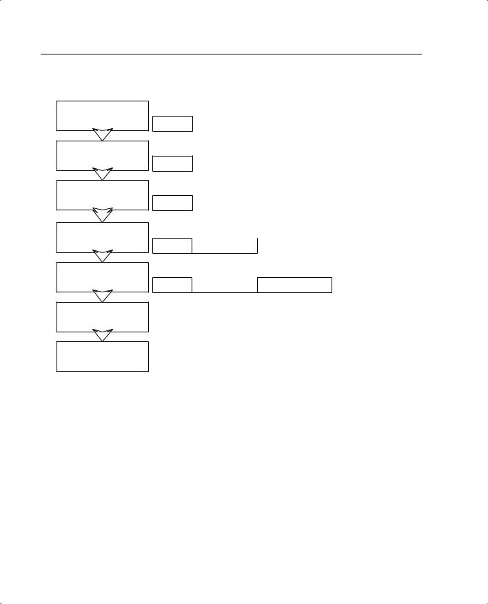
Traffic that traverses a network always has a source and destination address. This communication is based on the seven layers of the OSI reference model. Layers 5 through 7 (the upper layers) handle the application data, and Layers 1 through 4 (lower layers) are responsible for moving the data from the source to the destination. The data is created at the application layer (Layer 7) on the source machine. Transport information is added to the upperlayer data, and then network information, followed by data link information. At this point the information is transmitted across the physical medium as electronic signals. The upperlayer data combined with the transport information is called a segment. As soon as the network information is added to the segment, it is called a packet. The packet is encapsulated at the data link layer (Layer 2) with the addition of the source and destination MAC address and is now called a frame. Figure 5-1 shows how the data is encapsulated at each layer of the OSI reference model.
68 Chapter 5: Understanding Cisco PIX Firewall Translation and Connections
Figure 5-1 Encapsulation of Upper-Layer Data
Application |
|
|
|
Data |
|
|
|
Presentation |
|
|
|
Data |
|
|
|
Session |
|
|
|
Data |
|
|
|
Transport |
|
|
|
Data |
Transport Header |
|
|
Network |
|
Logical |
|
Data |
Transport Header |
||
Addressing |
|||
|
|
Data Link
Physical
Data |
Transport Header |
|
Logical |
Physical Addressing |
|
Addressing |
Error Checking |
||
|
|
|
||
|
|
|
|
|
Data |
Transport Header |
|
Logical |
Physical Addressing |
|
Addressing |
Error Checking |
||
|
|
|
The two transport protocols used by TCP/IP are Transmission Control Protocol (TCP) and User Datagram Protocol (UDP). These protocols are very different. Each has its strengths and weaknesses. For this reason, they are used in different ways to play on their strengths:
•TCP—a connection-oriented transport protocol that is responsible for reliability and efficiency of communication between nodes. TCP completes these tasks by creating connections as virtual circuits that act as two-way communications between the source and destination. TCP is very reliable and guarantees the delivery of data between nodes. TCP also can dynamically modify a connection’s transmission variables based on changing network conditions. TCP sequence numbers and TCP acknowledgment numbers are included in the TCP header. These features allow the source and destination to verify the correct, orderly delivery of data. Unfortunately, the overhead required for TCP can make it slow and keeps it from being the optimum transport protocol for some connections.
How the PIX Firewall Handles Traffic 69
•UDP—a connectionless transport protocol that is used to get the data to the destination. UDP provides no error checking, no error correction, and no verification of delivery. UDP defers the reliability issues to the upper-layer protocols and simply resends the data rather than verifying delivery. UDP is a very simple and very fast protocol.
The upper layers determine which of the transport protocols is used when data is encapsulated at the source node.
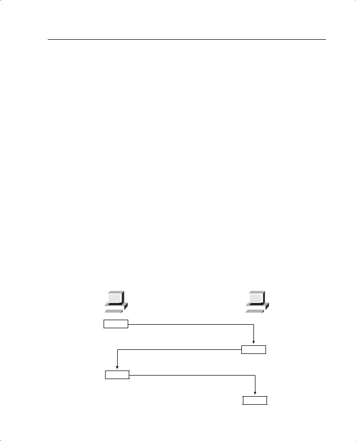
Figure 5-2 illustrates the TCP communication between nodes that do not have a firewall between them. This connection requires four different transmissions to negotiate the connection:
1The source sends a segment to the destination, asking to open a TCP session. A TCP flag is set to SYN, indicating that the source wants to initiate synchronization or a handshake. The source generates a TCP sequence number of 125.
2The destination receives the request and sends back a reply with the TCP flags ACK and SYN set, indicating an acknowledgment of the SYN bit (receive flow) and initiation of the transmit flow. It replies to the original TCP sequence number by adding 1, sending back a sequence number of 126. It also generates and sends its own TCP sequence number, 388.
3The source receives the SYN/ACK and sends back an ACK to indicate the acknowledgment of the SYN for the setup of the receive flow. It adds 1 to the value of the TCP sequence number generated by the destination and sends back the number 389.
4The acknowledgment is received, and the handshake is complete.
Figure 5-2 TCP Communication Between Nodes Without a PIX
|
Source |
Destination |
|||||||||
10.10.10.10 |
192.168.1.1 |
||||||||||
|
|
|
|
|
|
|
|
|
|
|
|
|
|
|
|
|
|
|
|
|
|
|
|
|
|
|
|
|
|
|
|
|
|
|
|
|
|
|
|
|
|
|
|
|
|
|
|
|
|
|
|
|
|
|
|
|
|
|
|
1
2
3
4
70 Chapter 5: Understanding Cisco PIX Firewall Translation and Connections
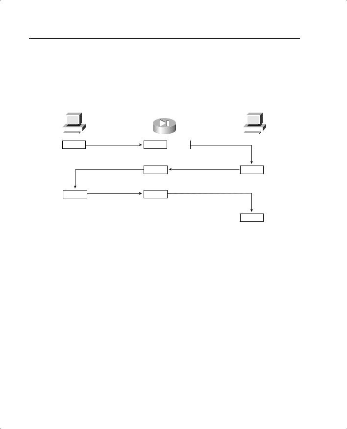
Now look at how this communication is handled by the Cisco PIX Firewall (see Figure 5-3).You first notice that the number of steps required for the same transaction has changed from four to eight, although everything appears to be the same to both the source and destination.
Figure 5-3 TCP Communication Between Nodes with a PIX
|
Source |
|
Destination |
|||||||||
10.10.10.10 |
PIX Firewall |
192.168.1.1 |
||||||||||
|
|
|
|
|
|
|
|
|
|
|
|
|
|
|
|
|
|
|
|
|
|
|
|
|
|
|
|
|
|
|
|
|
|
|
|
|
|
|
|
|
|
|
|
|
|
|
|
|
|
|
|
|
|
|
|
|
|
|
|
|
|
|
|
|
1 |
2 |
3 |
|
5 |
4 |
6 |
7 |
|
|
|
8 |
The following is a list of actions taken by the Cisco PIX Firewall when processing a TCP handshake and opening a TCP session (refer to Figure 5-3):
1The source machine initiates the connection by sending SYN. It is received by the Cisco PIX Firewall en route to the destination. PIX verifies the connection against the running configuration to determine if translation is to be completed. The running configuration is stored in memory, so this process occurs very quickly. The firewall checks to see if the inside address, 10.10.10.10, is to be translated to an outside address—in this case, 192.168.1.10 s/b 192.168.1.1. If the translation is to be completed, the PIX creates a translation slot if one does not already exist for this connection.
2All the session information is written to the state table, and the Cisco PIX Firewall randomly generates a new TCP sequence number. This connection slot is marked in the state table as an embryonic (half-open) connection.
3After the connection is verified against the security policy, the PIX allows the connection outside using the translated source address and the newly generated TCP sequence number.
4The destination receives the connection request (SYN) and replies with a SYN ACK.
5The PIX verifies the SYN ACK from the destination and matches the acknowledgment number against the randomly generated sequence number. It verifies the connection slot and forwards the connection back to the source using the original source address and sequence number plus 1.