


C H A P T E R 11
PIX Device Manager
The Cisco PIX Device Manager, hereafter referred to as PDM, is a browser-based configuration tool designed to help you set up, configure, and monitor your Cisco PIX Firewall graphically, without requiring extensive knowledge of the Cisco PIX Firewall command-line interface (CLI).
“Do I Know This Already?” Quiz
The purpose of this quiz is to help you determine your current understanding of the topics covered in this chapter. Write down your answers and compare them to the answers in Appendix A. If you have to look at any references to correctly answer the questions about PDM functionality, you should read the chapter.
1What happens to traffic that is not explicitly permitted by an access rule in an access control list?
2True or false: PDM supports a mixed configuration with outbound or conduit commands and access-list commands.
3What is a translation exemption rule?
4What are the six tabs on the PDM?
5How do you connect to the PDM?
6What version of PIX Software is required of PDM version 1.1?
7Which models of Cisco PIX Firewall are supported by PDM?
8What versions of Windows does PDM support?
9What steps should you take before installing PDM?
10True or false: PDM comes preinstalled on all PIX 5.3 and later software versions.
11Where does PDM reside?
210 Chapter 11: PIX Device Manager: PIX Device Manager
Foundation Topics
PDM Overview
PDM is a browser-based configuration tool designed to help you set up, configure, and monitor your Cisco PIX Firewall graphically. It is installed as a separate software image on the Cisco PIX Firewall and resides in the Flash memory of all PIX units running PIX version 6.0 and higher. PDM uses tables, drop-down menus, and task-oriented selection menus to assist you in administering your Cisco PIX Firewall. Additionally, PDM maintains compatibility with the PIX command-line interface (CLI) and includes a tool for using the standard CLI commands within the PDM application. PDM also lets you print or export graphs of traffic through the Cisco PIX Firewall and system activity.
NOTE PDM is a signed Java applet that downloads from the PIX Firewall to your web browser.
Figure 11-1 shows the PDM graphical user interface (GUI).
Figure 11-1 PIX Device Manager GUI
PIX Firewall Requirements to Run PDM 211
If your Cisco PIX Firewall unit is new and came with PIX version 6.0, the software is already loaded in Flash memory. If you are upgrading from a previous version of Cisco PIX Firewall, you need to use TFTP from the PIX unit’s inside interface to copy the PDM image to your Cisco PIX Firewall. PDM works with PIX Firewall version 6.0 and can operate on the PIX 506, 515, 520, 525, and 535 units as soon as they are upgraded to version 6.0.
PDM is designed to assist you in managing your network security by
•Letting you visually monitor your Cisco PIX Firewall system, connections, IDS, and traffic on the interfaces.
•Creating new PIX Firewall configurations or modifying existing configurations that were originally implemented using the PIX Firewall CLI or Cisco Secure Policy Manager (Cisco Secure PM).
•Using visual tools such as task-oriented selections and drop-down menus to configure your Cisco PIX Firewall.
•Using Secure Socket Layer (SSL) to secure communication between the PDM and the PIX.
•Monitoring and configuring PIX units individually.
Multiple Cisco PIX Firewalls can be monitored and configured from a single workstation via the web browser. It is also possible to have up to five administrators accessing a given PIX via PDM at the same time.
NOTE PDM cannot be used to configure PIX units that are being managed by Cisco Secure PM, because all changes made using PDM are overwritten the next time Cisco Secure PM synchronizes with the PIX. If there is a need to use both Cisco Secure PM and PDM, it is recommended that you use PDM for monitoring only, not configuration.
PIX Firewall Requirements to Run PDM
A PIX Firewall unit must meet the following requirements to run PDM:
•You must have an activation (license) key that enables Data Encryption Standard (DES) or the more secure 3DES, which PDM requires for support of the SSL protocol.
•PIX OS version 6.0 or higher.
•Minimum of 8 MB of Flash memory on the PIX unit.
The optimal configuration file size to use with PDM is less than 100 KB (which is approximately 1500 lines). Cisco PIX Firewall configuration files larger than 100 KB might interfere with PDM’s performance on your workstation. You can determine the size of your configuration file by entering the command show flashfs at a PIX CLI prompt. Then, look

212 Chapter 11: PIX Device Manager
for a line in the output that begins with file 1. The length number on the same line is the configuration file size in bytes. Example 11-1 provides sample output from show flashfs.
Example 11-1 show flashfs Command Output
pix# show |
flashfs |
|
|
flash file system: |
version:2 magic:0x12345679 |
||
file 0: origin: |
0 |
length:1540152 |
|
file 1: origin: 1572864 |
length:6458 |
||
file 2: origin: |
0 |
length:0 |
|
file 3: origin: 2752512 |
length:4539600 |
||
file 4: origin:16646144 |
length:280 |
||
Pix# |
|
|
|
|
|
|
|
PDM Operating Requirements
PDM’s requirements depend on the platform from which you run it. PDM is not supported on Macintosh, Windows 3.1, or Windows 95 operating systems.
Browser Requirements
The following are required to access PDM from a browser:
•PDM requires JavaScript and Java to be enabled. If you are using Microsoft Internet Explorer, your JDK version should be 1.1.4 or higher. To check which version you have, launch PDM. When the PDM information window comes up, the field JDK Version indicates your JDK version. If you have an older JDK version, you can get the latest JVM from Microsoft by downloading the product called Virtual Machine.
•Browser support for SSL must be enabled. The supported versions of Internet Explorer and Netscape Navigator support SSL without requiring additional configuration.
Windows Requirements
The following are required to access PDM from a Windows NT/2000 operating system:
•Windows 2000 (Service Pack 1), Windows NT 4.0 (Service Pack 4 and higher), Windows 98, or Windows Me.
•Supported browsers: Internet Explorer 5.0 (Service Pack 1) or higher (5.5 recommended), Netscape Communicator 4.51 or higher (4.76 recommended). Internet Explorer is recommended due to its faster load times.
•Any Pentium or Pentium-compatible processor running at 350 MHz or higher.
•At least 128 MB of RAM. 192 MB or more is recommended.

PDM Installation and Configuration 213
•An 800× 600-pixel display with at least 256 colors. A 1024× 768-pixel display and at least High Color (16-bit) colors are recommended.
SUN Solaris Requirements
The following requirements apply to the use of PDM with Sun SPARC:
•Sun Solaris 2.6 or later running CDE or OpenWindows window manager.
•SPARC microprocessor.
•Supported browser: Netscape Communicator 4.51 or higher (4.76 recommended).
•At least 128 MB of RAM.
•800× 600 pixel display with at least 256 colors. A 1024× 768 pixel display and at least High Color (16-bit) colors are recommended.
NOTE PDM does not support Solaris on IBM PCs.
Linux Requirements
The following requirements apply to the use of PDM with Linux:
•Red Hat Linux 7.0 running the GNOME or KDE 2.0 desktop environment.
•Supported browser: Netscape Communicator 4.75 or a later version.
•At least 64 MB of RAM.
•An 800× 600-pixel display with at least 256 colors. A 1024× 768-pixel display and at least High Color (16-bit) colors are recommended.
PDM Installation and Configuration
Two versions of PDM are currently available:
•
•
PDM version 1.1—Requires PIX software 6.0 or 6.1
PDM version 2.1—Requires PIX software 6.2
Both PDM versions are available on all PIX 501, 506/506E, 515/515E, 520, 525, and 535 platforms that are running Cisco PIX Firewall software version 6.0 or later. PDM version 2.0 requires Cisco PIX Firewall software version 6.2. If you are using Cisco PIX Firewall software version 6.0 or 6.1, use PDM version 1.1.

214 Chapter 11: PIX Device Manager
Before installing PDM, follow these steps:
Step 1 Save or print your PIX configuration, and write down your activation key.
Step 2 If you are upgrading from a previous version of PIX, you need to obtain the PDM software from Cisco in the same way you download the Cisco PIX Firewall software. Then use TFTP to download the image to your PIX unit.
Step 3 If you upgrade your Cisco PIX Firewall software to version 6.0 or higher and you plan to use PDM, both the PIX image and the PDM image must be installed on your failover units.
The upgrade procedure is very similar to that of the Cisco PIX Firewall image upgrade. Example 11-2 shows the installation procedures for PDM installation.
Example 11-2 PDM Installation Procedures
PIXFIREWALL(config)# copy tftp flash:pdm
Address or name of remote host [127.0.0.1] 10.1.1.10 Source file name [cdisk]pdm-202.bin
copying tftp://10.1.1.10/cdisk to flash:pdm [yes | no | again]y
After you succesfully install your PDM, you are ready to access it using your web browser. On a browser running on a workstation connected to the PIX unit, enter the following:
https://PIX_Inside_Interface_IP_Address
This launches the PDM applet. Use your enable password and leave the username blank to access the PDM interface when prompted to provide a username and password.
NOTE Remember that you have to use HTTPS and not HTTP when accessing the PDM. Otherwise, the browser cannot get connected.
Using the PDM to Configure the Cisco PIX Firewall
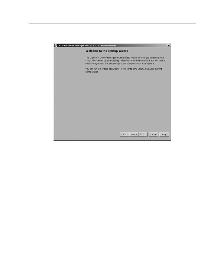
The Cisco PIX Firewall Device Manager Startup Wizard, shown in Figure 11-2, walks you through the initial configuration of your Cisco PIX Firewall. You are prompted to enter information about your PIX Firewall. The Startup Wizard applies these settings, so you should be able to start using your PIX Firewall right away.
PDM Installation and Configuration 215
Figure 11-2 Cisco PIX Firewall Device Manager Startup Wizard Screen
The Startup Wizard configures the following attributes on your Cisco PIX Firewall:
•A host name for your PIX.
•A domain name for your PIX.
•A default gateway for your PIX.
•An enable password that is required to access PDM or the PIX’s CLI.
•The speed and IP address information of the outside interface on the PIX.

216Chapter 11: PIX Device Manager
•Your PIX’s other interfaces, such as the inside or DMZ interfaces, can be configured from the Startup Wizard.
•Network Address Translation (NAT) or Port Address Translation (PAT) rules for your PIX.
•Dynamic Host Configuration Protocol (DHCP) settings for the inside interface, as a DHCP server.
•If you are using a PIX 501 or 506, the Startup Wizard lets you configure Cisco Easy VPN Remote device settings, which let the PIX act as a VPN client and establish a VPN tunnel to the VPN server.
The Startup Wizard helps you set up a shell configuration—a basic configuration for your Cisco PIX Firewall. To customize and modify your PIX configuration, PDM provides you with six main tabs:
•
•
•
•
•
•
System Properties
Hosts/Networks
Translation Rules
Access Rules
VPN
Monitoring
The sections that follow examine the System Properties, Hosts/Networks, Translation Rules, Access Rules, and Monitoring tabs of the PIX Device Manager in more detail. The section, “Using PDM to Create a Site-to-Site VPN,” describes all actions associated with the VPN tab.
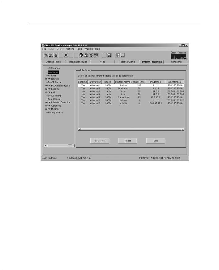
System Properties
The System Properties tab, shown in Figure 11-3, lets you view and configure all the parameters that can be configured using the Startup Wizard. Basic configurations such as interface definition and configurations, password, clock, and Telnet configuration are all done at this tab. In addition to the basic configuration, the System Properties tab lets you perform advanced configuration typically done at the CLI. You can configure logging; authentication, authorization, and accounting (AAA); multicast; TurboACL; intrusion detection; and more through the user-friendly interface of the System Properties panel.
PDM Installation and Configuration 217
Figure 11-3 System Properties Tab on the PDM
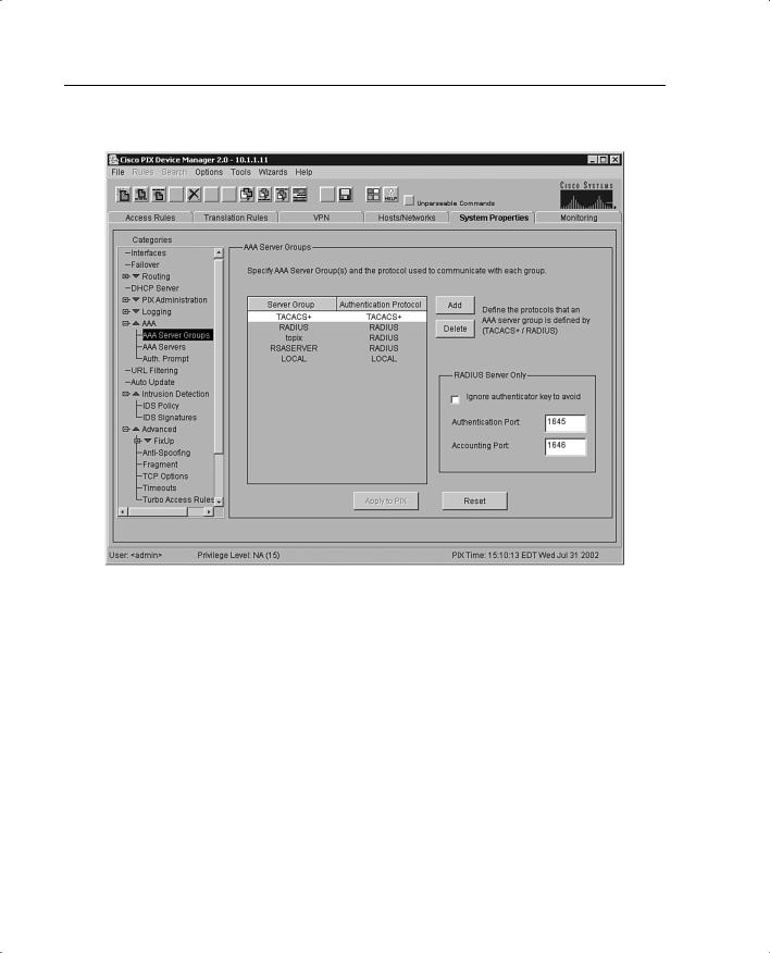
Complicated configurations such as AAA have been made significantly more intuitive and easier with the system properties under AAA. The AAA Server Groups panel, shown in Figure 11-4, allows you to specify up to 14 AAA server groups for your network.
218 Chapter 11: PIX Device Manager
Figure 11-4 AAA Server Groups Panel Under the System Properties Tab
Each AAA server group directs different types of traffic to the authentication servers in its group. If the first authentication server listed in the group fails, the PIX seeks authentication from the next server in the group. You can have up to 16 groups, and each group can have up to 16 AAA servers for a total of up to 256 AAA servers.
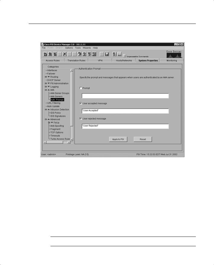
The Authentication Prompt panel lets you change the AAA challenge text for HTTP, FTP, and Telnet access. Figure 11-5 shows prompt messages that can be configured when users authenticate by a AAA server.
PDM Installation and Configuration 219
Figure 11-5 Configurable Prompt Messages
If configured, the prompt text appears above the username and password prompts that users view when logging in. If you do not use this feature, FTP users view FTP authentication, HTTP users view HTTP authentication, and challenge text does not appear for Telnet access. If the user authentication occurs from Telnet, you can use the user accepted and user rejected options to display different authentication prompts if the authentication server accepts or rejects the authentication attempt. Chapters 13 and 14 discuss AAA in further detail.
Another example of a command-line task that has been streamlined by the System Properties page is URL filtering. The URL Filtering panel lets you prevent internal users from accessing external URLs that you designate using the Websense URL filtering server. After you have defined your URL filtering server(s) and related parameters on this panel, use the Filter Rules panel to define the rules that will be used to enforce URL filtering.
NOTE A total of 16 URL servers can be configured.
220 Chapter 11: PIX Device Manager
The PIX Firewall can be configured to use either N2H2 or Websense, but not both. For example, if the PIX unit is configured to use two Websense servers, when N2H2 is selected, a warning appears after you add the first N2H2 server and click Apply To PIX. All the previously configured Websense servers are dropped, and the new N2H2 server is added. This also takes place when you switch from N2H2 to Websense. Content filtering is discussed further in Chapter 12, “Content Filtering on the PIX Firewall.”
Hosts/Networks
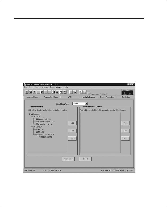
The Hosts/Networks tab, shown in Figure 11-6, lets you view, edit, add to, and delete from the list of hosts and networks defined for the selected interface defined previously on the System Properties tab.
Figure 11-6 Hosts/Networks Tab on the PDM
The PDM requires that you define any host or network that you intend to use in access rules and translations. These hosts or networks are organized below the interface from which they can be reached.
PDM Installation and Configuration 221
Access rules reference these hosts or networks in a rule’s source and destination conditions, whereas translation rules reference them in a rule’s original address condition. When defining either type of rule, you can reference a host or network by clicking Browse in the appropriate Add or Edit Rule dialog box. Additionally, you can reference the host or network by name if a name is defined for it.
In addition to defining the basic information for these hosts or networks, you can define route settings and NAT rules for any host or network. You can also configure route settings on the System Properties tab and translation rules on the Translation Rules tab. These different configuration options accomplish the same results. The Hosts/Networks tab provides another way to modify these settings on a per-host or per-network basis.
Translation Rules
The Translation Rules tab, shown in Figure 11-7, lets you view all the address translation rules or NAT exemption rules applied to your network.
Figure 11-7 Translation Rules Tab on the PDM

222 Chapter 11: PIX Device Manager
The Cisco PIX Firewall supports both NAT, which provides a globally unique address for each outbound host session, and PAT, which provides a single, unique global address for up to 64,000 simultaneous outbound or inbound host sessions. The global addresses used for NAT come from a pool of addresses to be used specifically for address translation. The unique global address that is used for PAT can be either one global address or the IP address of a given interface.
From the Translation Rules tab you can also create a translation exemption rule, which lets you specify traffic that is exempt from being translated or encrypted. The exemption rules are grouped by interface in the table, and then by direction. If you have a group of IP addresses that will be translated, you can exempt certain addresses from being translated using the exemption rules. If you have a previously configured access list, you can use that to define your exemption rule. PDM writes a nat 0 command to the CLI. You can re-sort your exemption’s view by clicking the column heading.
It is important to note that the order in which you apply translation rules can affect how the rules operate. PDM lists the static translations first and then the dynamic translations. When processing NAT, the Cisco PIX Firewall first translates the static translations in the order they are configured. You can select Rules > Insert Before or Rules > Insert After to determine the order in which static translations are processed. Because dynamically translated rules are processed on a best-match basis, the option to insert a rule before or after a dynamic translation is disabled.
Access Rules
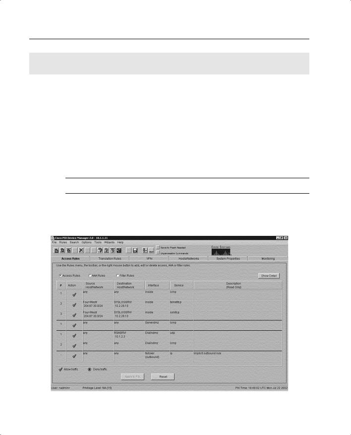
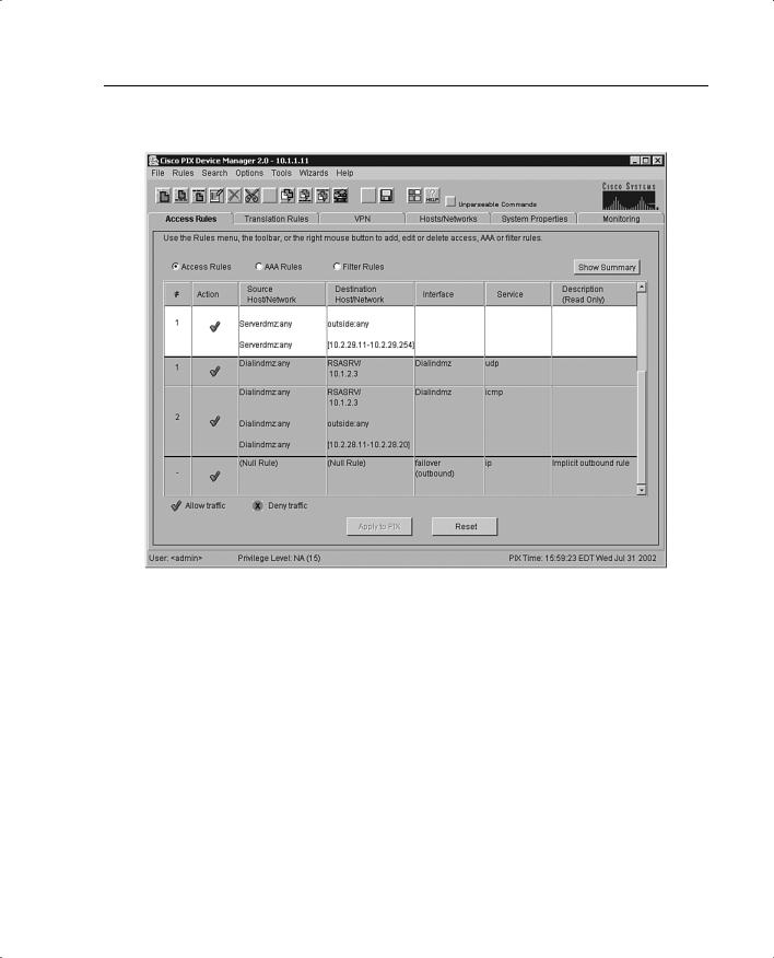
The Access Rules tab, shown in Figure 11-8, shows your entire network security policy expressed in rules. This tab combines the concepts of access lists, outbound lists, and conduits to describe how a specific host or network interacts with another host or network to permit or deny a specific service and/or protocol. This tab also lets you define AAA rules and filter rules for ActiveX and Java.
PDM Installation and Configuration 223
Figure 11-8 Access Rules Tab on the PDM
Access rules are categorized into two modes:
•
•
Access control list mode (the default)
Conduit and outbound list mode
If your PIX currently has a working configuration using either conduit commands, outbound commands, or access lists, PDM continues using your current model. If the Cisco PIX Firewall is currently using conduit commands to control traffic, PDM adds more conduit commands to your configuration as you add rules. Similarly, if your PIX is currently configured using access-list commands, the PDM adds more access-list commands to your configuration as you add rules. If you have a Cisco PIX Firewall with no previous configuration, PDM adds access-list commands to the CLI by default. PDM does not support a mixed configuration with outbound commands or conduit commands and access-list commands.
Keep in mind the following points when creating access rules with the PDM:

224Chapter 11: PIX Device Manager
•It is important to remember that you cannot define any access rules until static or dynamic NAT has been configured for the hosts or networks on which you want to permit or deny traffic.
•You cannot use unavailable commands until your rule meets certain conditions, such as defining hosts or networks. Unavailable commands appear dimmed on the Rules menu. For example, Insert Before and Insert After are available only after a rule is highlighted. Paste is available only when a rule has been copied or cut.
•Access rules are listed in sequential order and are applied in the order in which they appear on the Access Rules tab. This is the order in which the PIX evaluates them. An implicit, unwritten rule denies all traffic that is not permitted. If traffic is not explicitly permitted by an access rule, it is denied.
Null Rules
A null rule indicates that an access rule was configured for a host that is not visible on another interface. This rule is null because no traffic can flow between these two hosts even though the access rule would permit it. Table 11-1 shows an example of a null rule.
Table 11-1 Null Rule Example
|
|
Source Host/ |
Destination Host/ |
|
|
|
# |
Action |
Network |
Network |
Interface |
Service |
Description |
|
|
|
|
|
|
|
1 |
√ |
(null rule) |
(null rule) |
[inbound] |
tcp |
|
This can happen when PDM reads in an existing configuration where any of the following exists:
•
•
•
Inbound rules without a static translation
Outbound rules without NAT
No hosts or networks are defined for either source or destination
Monitoring
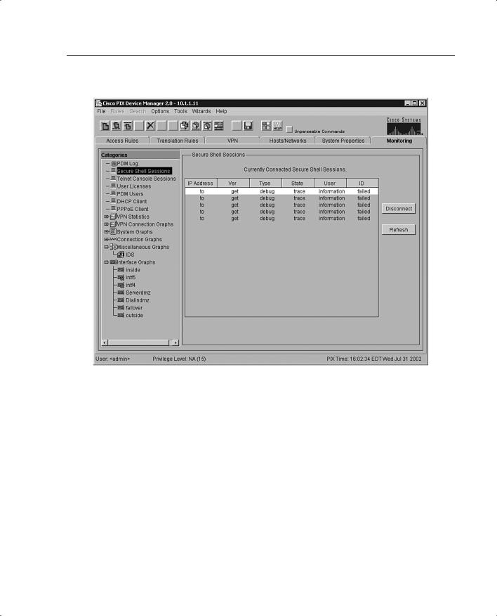
The Monitoring tab, shown in Figure 11-9, is one of the most useful tools to help you make sense of the different statistics that the Cisco PIX Firewall can generate. The different panels on the monitoring tab help you analyze your PIX’s performance using colorful graphs.
PDM Installation and Configuration 225
Figure 11-9 Monitoring Tab on the PDM
The Monitoring tab features two types of graphing and monitoring functions:
•The first type has a unique screen for each menu selection that shows the table of statistics, numeric values, or settings for that menu selection.
•The second type uses the same screen, which allows the building of graph windows that combine up to four graphs in a single window.
The graphs displayed in the New Graph window can be printed or bookmarked in your browser for later recall, or the data may be exported for use by other applications.
The following options can provide monitoring statistics on the Cisco PIX:
•The PDM Log panel displays the syslog messages currently in the PDM Log buffer on the PIX. A snapshot of the PDM Log buffer contents on the PIX can be displayed.
•The Secure Shell Sessions panel allows you to monitor connections made to the PIX Firewall using Secure Shell (SSH). When the Secure Shell panel is displayed, a snapshot of the current SSH sessions to the PIX Firewall is available.

226Chapter 11: PIX Device Manager
•The Telnet Console Sessions panel allows you to monitor connections made to the PIX Firewall using Telnet. A snapshot of current Telnet sessions to the PIX Firewall is displayed.
•The User Licenses panel displays the number of current users, which is subtracted from the maximum number of users for your PIX Firewall licensing agreement.
•The PDM Users panel allows you to monitor connections made to the PIX Firewall using PDM. A snapshot of the current PDM user sessions to the PIX Firewall is displayed.
•The DHCP Client panel displays DHCP-assigned interface parameters when DHCP addressing is configured on the outside interface of the PIX Firewall. A snapshot of the current DHCP lease information is displayed.
•The PPPoE Client panel allows the PIX Firewall to automatically connect users on the inside interface to Internet service providers (ISPs) via the outside interface.
•The VPN Statistics panel lets you graphically monitor the following functions:
—Number of active Phase 2 IPSec tunnels
—Number of active Phase 2 IKE tunnels
—L2TP active tunnels
—L2TP active sessions
—PPTP active tunnels
—PPTP active sessions
—Detailed IPSec information (similar to the CLI command show ipsec sa detail)
•The System Graphs panel allows you to build the New Graph window, which monitors the PIX Firewall’s system resources, including block utilization, CPU utilization, failover statistics, and memory utilization
•The Connection Graphs panel allows you to monitor a wide variety of performance statistics for PIX Firewall features, including statistics for xlates, connections, AAA, fixups, URL filtering, and TCP intercept
•The IDS panel under the Miscellaneous panel allows you to monitor intrusion detection statistics, including packet counts for each Intrusion Detection System (IDS) signature supported by the PIX Firewall.
•The Interface Graphs panel allows you to monitor per-interface statistics, such as packet counts and bit rates, for each enabled interface on the PIX Firewall.
NOTE |
If an interface is not enabled using the System Properties tab panel, no graphs are available |
|
for that interface. |
|
|
Using PDM for VPN Configuration 227
Using PDM for VPN Configuration
Chapter 10, “Virtual Private Networks,” explained how to configure VPN on the Cisco PIX Firewall via the command-line interface. One of the difficult configuration and troubleshooting issues occurs with VPNs. Quite often, typos occur when you create a VPN configuration via the CLI. For novice administrators of the Cisco PIX Firewall, the commands and remembering their sequence can be overwhelming. The PDM presents a user-friendly VPN Wizard that creates both site-to-site and remote VPNs for the Cisco PIX Firewall. Administrators are prompted for unique parameters such as IP addresses, and they use drop-down menus to configure their VPN. The following sections present step-by-step instructions on using the PDM to create both a site-to-site VPN and a remote-access VPN.
Using PDM to Create a Site-to-Site VPN
The following steps and figures show a sample site-to-site VPN configuration using the VPN Wizard on the PDM:
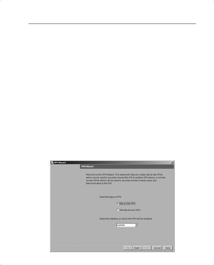
Step 1 Select the Site to Site VPN button, as shown in Figure 11-10, to create a site-to-site VPN configuration. This configuration is used between two IPSec security gateways, which can include Cisco PIX Firewalls, VPN concentrators, or other devices that support site-to-site IPSec connectivity. Use this panel to also select the type of VPN tunnel you are defining and to identify the interface on which the tunnel will be enabled. In Figure 11-10, the outside interface is selected as the VPN termination point.
Figure 11-10 VPN Wizard with Site-to-Site VPN Selected
228 Chapter 11: PIX Device Manager
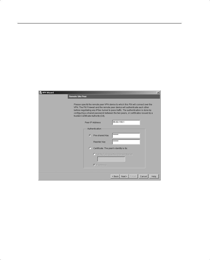
Step 2 On the Remote Site Peer panel, shown in Figure 11-11, you specify the IP address of the remote IPSec peer that will terminate the VPN tunnel you are configuring. Also, you use this panel to identify which of the following methods of authentication you want to use:
—Preshared keys
—Certificates
Figure 11-11 shows the Remote Site Peer panel configured with the remote IPSec peer and the preshared authentication keys.
Figure 11-11 Remote Site Peer Panel
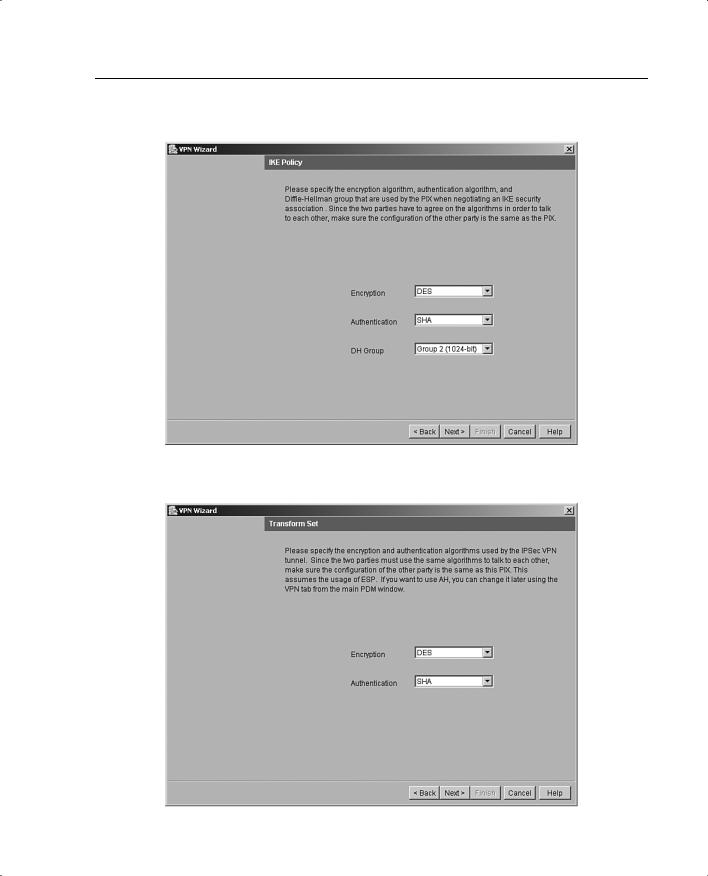
Step 3 Configure the encryption and authentication algorithms for IKE Phase I. Figure 11-12 shows the IKE Policy panel.
Step 4 Configure the transform set to specify the encryption and authentication algorithms used by IPSec, as shown in Figure 11-13. IPSec provides secure communication over an insecure network, such as the public Internet, by encrypting traffic between two IPSec peers, such as your local PIX and a remote PIX or VPN concentrator.
Using PDM for VPN Configuration 229
Figure 11-12 IKE Policy Panel
Figure 11-13 Transform Set Panel
230 Chapter 11: PIX Device Manager
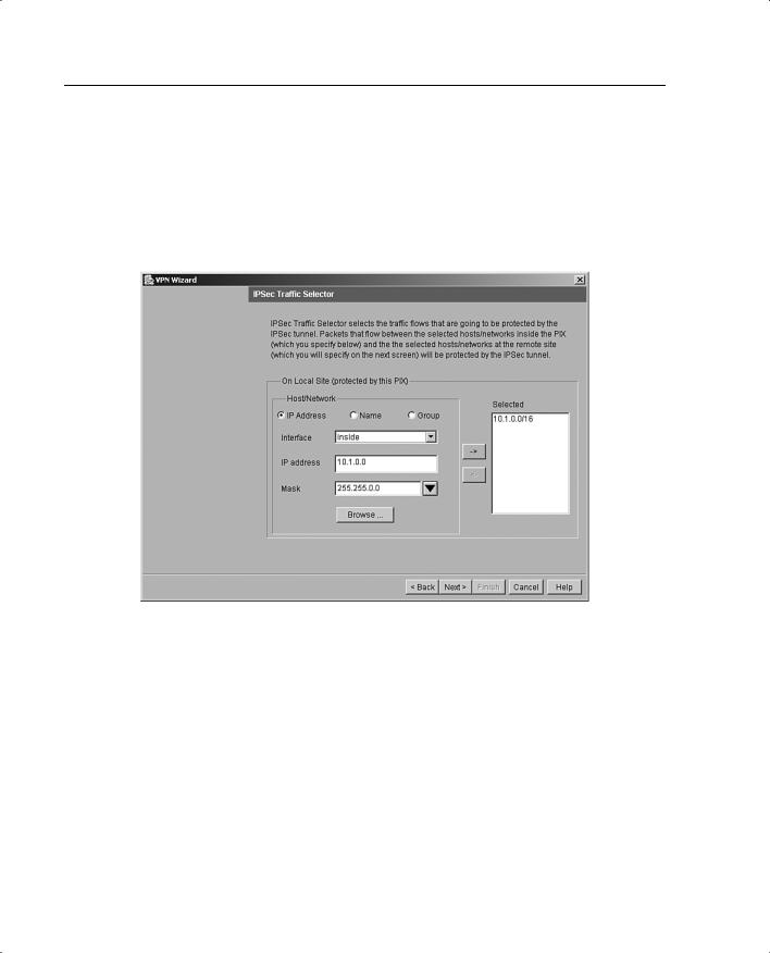
Step 5 Identify the traffic you want to protect using the current IPSec tunnel, as shown in Figure 11-14. The current IPSec tunnel protects packets that are sent to or received from the hosts or networks you select on this panel.
Use this panel to identify the hosts and networks protected by your local Cisco PIX Firewall. In Figure 11-14, packets that are sent to and received from the 10.1.0.0/16 network are protected.
Figure 11-14 IPSec Traffic Selector Panel: On Local Site
Step 6 Identify the hosts and networks protected by the remote IPSec peer, as shown in Figure 11-15.
Step 7 At this point, the site-to-site VPN configuration has been completed but not yet written to the PIX. When you click Finish, a dialog box with CLI commands appears, as shown in Figure 11-16. You can review your configuration in that dialog box and click Send to write the configuration to the PIX.
Using PDM for VPN Configuration 231
Figure 11-15 IPSec Traffic Selector Panel: On Remote Site
Figure 11-16 CLI Command Preview in PDM
232 Chapter 11: PIX Device Manager
Using PDM to Create a Remote-Access VPN
With a remote-access VPN, your local Cisco PIX Firewall provides secure connectivity between individual remote users and the LAN resources protected by your local PIX.
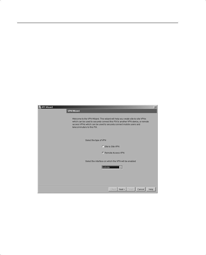
Step 1 From the opening screen of the PDM VPN Wizard, shown in Figure 11-17, select the Remote Access VPN button to create a remote-access VPN configuration. This configuration allows secure remote access for VPN clients, such as mobile users. A remote-access VPN allows remote users to securely access centralized network resources. When you select this option, the system displays a series of panels that let you enter the configuration required for this type of VPN. In Figure 11-17, the outside interface is selected as the interface on which the current VPN tunnel will be enabled.
Figure 11-17 VPN Wizard with Remote Access VPN Selected
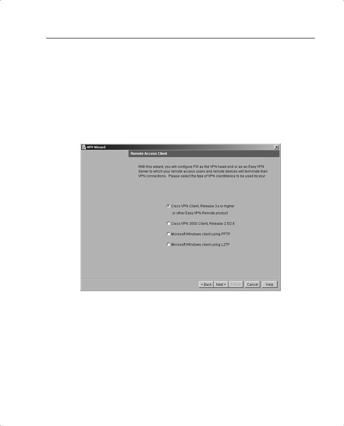
Step 2 On the Remote Access Client panel, shown in Figure 11-18, identify the type of remote access client that will use the current VPN tunnel to connect to your local Cisco PIX Firewall. The options are as follows:
—Cisco VPN Client—Select this button to support remote-access clients using Cisco VPN Client v3.x or higher (Cisco Unified VPN Client Framework).
Using PDM for VPN Configuration 233
—Cisco VPN 3000 Client—Select this button to support remoteaccess clients using Cisco VPN 3000 Client, Release 2.5/2.6.
—Microsoft Windows client using PPTP—Select this button to support remote-access clients using Microsoft Windows client using Point-to-Point Tunneling Protocol (PPTP).
—Microsoft Windows client using L2TP—Select this button to support remote-access clients using Microsoft Windows client using Layer 2 Tunneling Protocol (L2TP).
Figure 11-18 Remote Access Client Panel
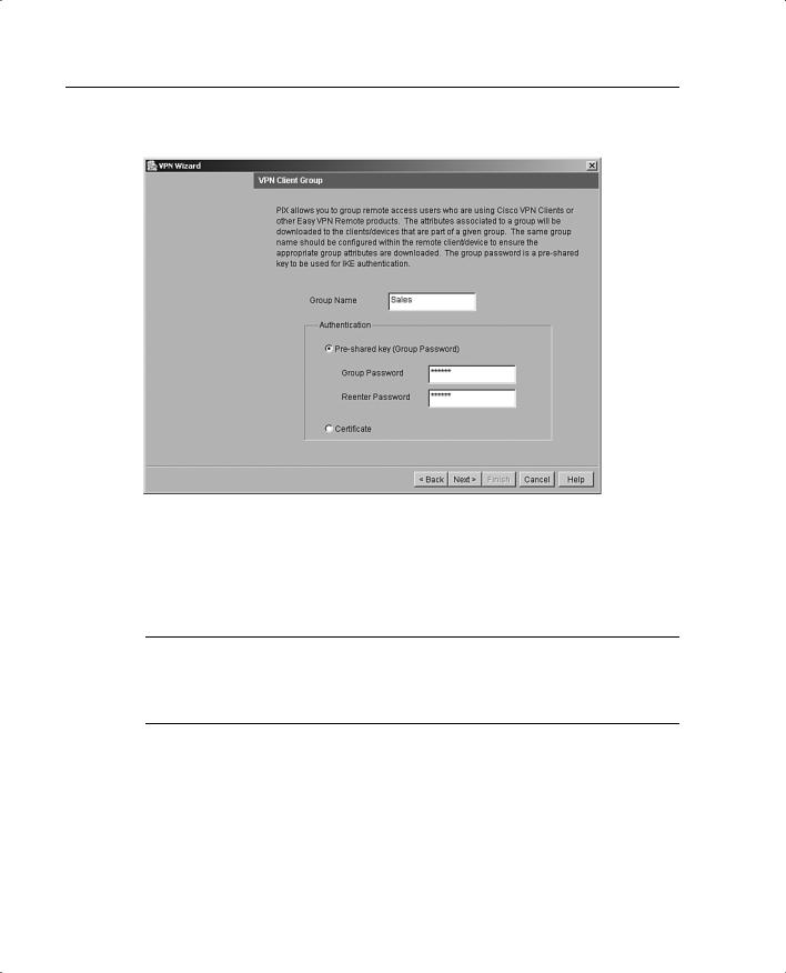
Step 3 Create a VPN client group to group remote-access users who are using the Cisco VPN client. The attributes associated with a group are applied and downloaded to the client(s) that are part of a given group. The Group Password is a preshared key to be used for IKE authentication. Figure 11-19 shows the VPN Client Group panel with Sales as a group name and Preshared key selected for IKE authentication.
234 Chapter 11: PIX Device Manager
Figure 11-19 VPN Client Group Panel
A preshared key is a quick and easy way to set up communication with a limited number of remote peers. To use this method of authentication, exchange the preshared key with the remote-access user through a secure and convenient method, such as an encrypted e-mail message.
NOTE Preshared keys must be exchanged between each pair of IPSec peers that need to establish secure tunnels. This authentication method is appropriate for a stable network with a limited number of IPSec peers. It might cause scalability problems in a network with a large or increasing number of IPSec peers.
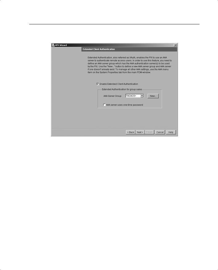
Step 4 Use the Extended Client Authentication panel, shown in Figure 11-20, to require VPN client users to authenticate from a AAA server for access to the private network on your PIX Firewall. Extended client authentication is optional and is not required for VPN client access to the private network.
Using PDM for VPN Configuration 235
Figure 11-20 Extended Client Authentication Panel
Extended authentication (Xauth) is a feature within the IKE protocol. Xauth lets you deploy IPSec VPNs using TACACS+ or RADIUS as your user authentication method. This feature, which is designed for VPN clients, provides user authentication by prompting the user for a username and password and verifies them with the information stored in your TACACS+ or RADIUS database. Xauth is negotiated between IKE Phase 1 (the IKE device authentication phase) and IKE Phase 2 (the IPSec SA negotiation phase). If Xauth fails, the IPSec security association is not established, and the IKE security association is deleted.
The AAA server must be defined before Xauth will work on the Cisco PIX Firewall. You can define the AAA server using the New button. This opens the AAA Server Group panel, where you can define the location of the AAA server, the group name, and the protocol used for AAA.
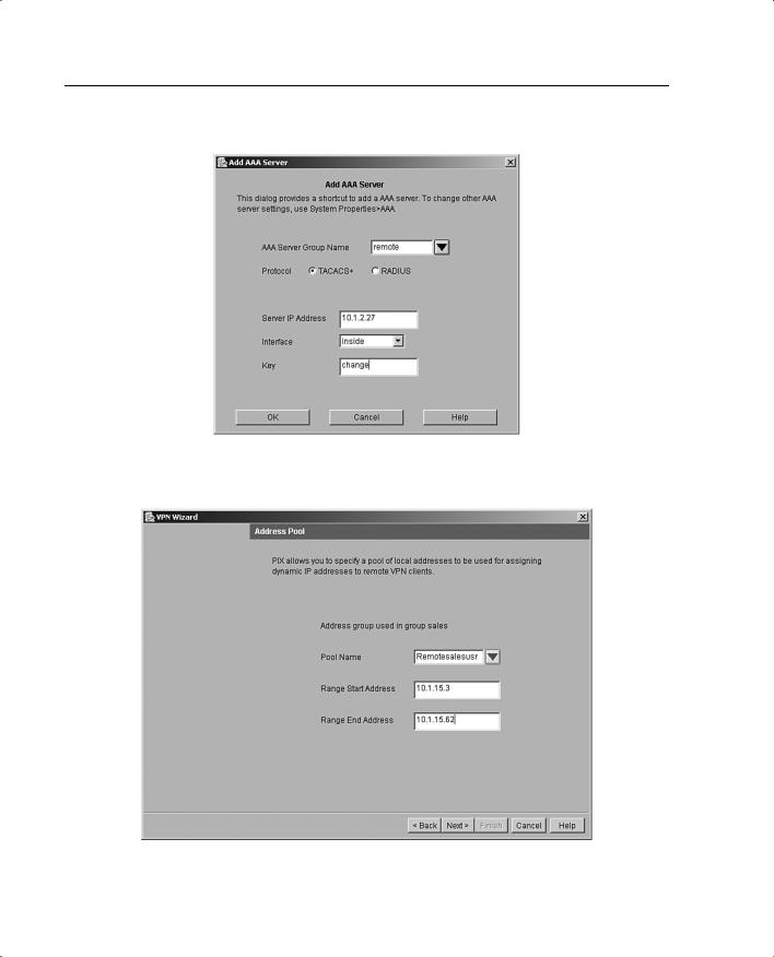
Step 5 Define the location of the AAA server, the group name, and the protocol used for AAA, as shown in Figure 11-21.
Step 6 Create a pool of local addresses that can be used to assign dynamic addresses to remote VPN clients. Enter a descriptive identifier for the address pool. Figure 11-22 shows a sample configuration for the remote sales group in the Address Pool panel.
236 Chapter 11: PIX Device Manager
Figure 11-21 AAA Server Group Window
Figure 11-22 Address Pool Panel
Using PDM for VPN Configuration 237
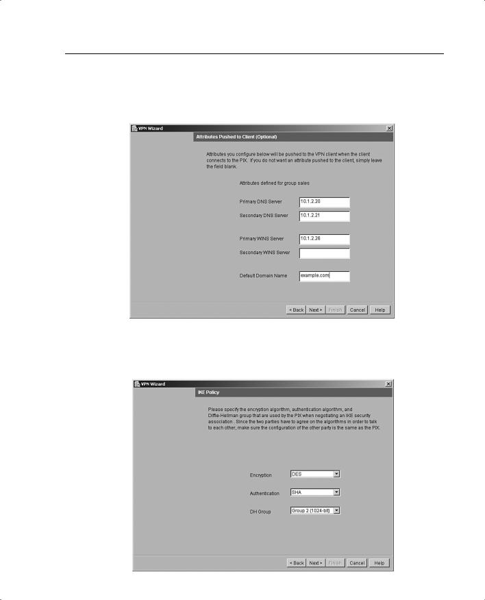
Step 7 (Optional) Configure the DNS and WINS addresses that can be pushed down to the remote client, as shown in Figure 11-23.
Figure 11-23 Attributes Pushed to Client Panel
Step 8 Specify the encryption and authentication algorithms used by IKE (Phase 1), as shown in Figure 11-24.
Figure 11-24 IKE Policy Panel
238 Chapter 11: PIX Device Manager
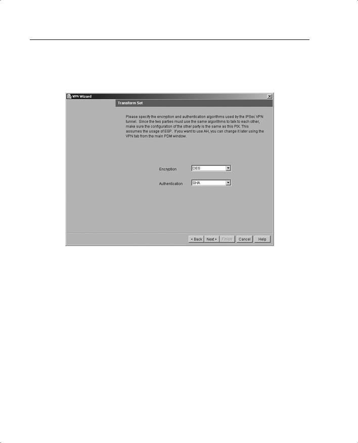
Step 9 Specify the encryption and authentication algorithms used by the IPSec VPN tunnel, as shown in Figure 11-25.
Figure 11-25 Transform Set Panel
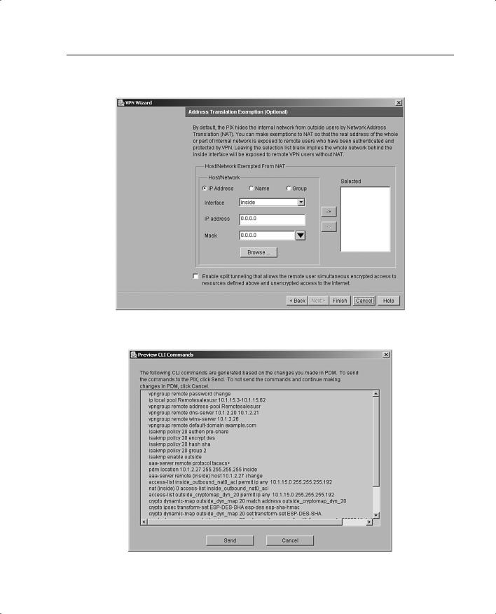
Step 10 (Optional) The Address Translation Exemption panel, shown in Figure 11-26, identifies local hosts/networks that are to be exempted from address translation. By default, the PIX hides the real IP address of internal networks from outside hosts through dynamic or static NAT. The security provided by NAT is essential to minimize the risk of being attacked by untrusted outside hosts, but it might be inappropriate for those who have been authenticated and protected by VPN.
Step 11 After you click Finish, the PDM VPN Wizard displays your configuration in CLI format, as shown in Figure 11-27. When you click Send, the commands that were configured via the PDM are sent to the PIX. You also have the option of canceling the configuration.
Using PDM for VPN Configuration 239
Figure 11-26 Address Translation Exemption Panel
Figure 11-27 CLI Command Preview in PDM