

Architectural Structures
.pdfG G Schierle Architectural Structures
G G Schierle
Architectural Structures
Excerpts
ISBN 0-18-195009-x
Copyright © G Schierle 1990-2006. All rights reserved
Portions of this document reproduce sections from the 2003 International Building Code, International Code Council, Falls Church, Virginia. All rights reserved.
AISC data, copyright © American Institute of Steel Construction, Inc. Reprinted with permission. All rights reserved
USGS data copyright © United States Geological Survey, courtesy USGS
University of Southern California Custom Publishing
C/O Chauncey Jemes
Los Angeles, CA 90089-2540 e-mail:jemes@usc.edu
Tel. 213-740-8946
Fax: 213-740-7686
Preface
To foster informed intuition for structures, this book has many illustrations visualizing structural behavior and to complement and clarify mathematical concepts. While the book is primarily targeted for students of architecture, it also serves as reference book for students of civil engineering, and professional architects, engineers, and contractors. The book is organized in six parts. Part I starts with an introduction of key developments in the historic evolution of structures and proceeds to introduce loads on buildings and basic systems to resist them. Part II introduces fundamentals: statics and strength of material, as well as analysis and design of basic elements, such as beams and columns. Part III introduces design methods: ASD and LRFD; design of masonry (ASD) and concrete (strength method); design for wind and seismic forces; as well as conceptual design, explored on case studies. Part IV introduces structure systems for horizontal spans, categorized by bending, axial, form, and tensile resistance. All systems are introduced with conceptual diagrams, describing their structural behavior and alternate options. Case studies describe their use in real projects. Part V introduces vertical structures in similar fashion. Part VI introduces material properties and details for wood, steel, masonry, concrete, and membrane structures. Appendices include math derivation, graphs and tables. Text and graphics are correlated on the same page for easy reading and comprehension. Prerequisites for the book are algebra, trigonometry, and Newtonian physics. The book can be used in courses of statics and strength of material, structure systems and structural materials. Math derivations visualized help understanding and to introduce concepts also to readers with more artistic or visual modes of learning. The book includes many graphs to streamline complex tasks. The graphs, which feature US and SI units to facilitate correlation, include:
•Design graphs for span limits and span/depth ratios
•Column design graphs
•Seismic design graphs
•Wind design graphs
Acknowledgements
I am grateful to many students and others for various contributions to this book, ranging from suggestions to illustrations; most notably drawings by Bronne Dytog and June Yip; but also Xiaojun Cheng. Lucia Ho, Maki Kawaguchi, Ping Kuo, Jennifer Lin, Sassu Mitra, Rick Patratara, Shina Rau, Srinivas Rau, Madhu Thangavelu, and Sharmilla Thanka. Students that provided data and comments include Laura Mae Bryan, Sabina Cheng, Samy Chong, Claudia Chiu, Kristin Donour, Miriam Figueroa, Ping Han, Nick Ketpura, Samuel Kuo, Jason Mazin, Neha Sivaprasad, Timothy Petrash, Musette Profant, Katie Rahill, Reed Suzuki, Bogdan Tomalevski, Carole Wong, Nasim Yalpani. Others that provided comments or material: include: Andrea Cohen Gehring, Jeff Guh, Robert Harris, Theo Heizmann, Helge Wang, Will Shepphird, Robert Timme, Matt Warren, and Walter Winkle. Architects and engineers that provided drawings include: Norman Foster, Von Gerkan Marg, Arata Isozaki, David Lawrence Gray, Paul M. Kaufmann, Pierre Koenig, Panos Koulermos, Edward Niles, Jörg Schlaich, James Tyler, Widom Wein Cohen, and Dimitry Vergun.
To my family
Units
SI * units (metric) |
|
|
Conversion |
|
|
US units |
|
|
|
|
Remark |
|
factor ** |
|
|
|
Remark |
|
|
|
|
Length |
|
|
|
|
Millimeter |
mm |
|
25.4 |
Inch |
in |
|
||
Centimeter |
cm |
10 mm |
30.48 |
Foot |
ft |
12 in |
||
Meter |
m |
1000 mm |
0.9144 |
Yard |
yd |
3 ft |
||
Kilometer |
km |
1000 m |
1.609 |
Mile |
mi |
5280 ft |
||
|
|
|
|
Area |
|
|
|
|
Square millimeter |
mm2 |
|
645.16 |
Square in |
in2 |
|
||
Sq. centimeter |
cm2 |
100 mm2 |
929 |
Square foot |
ft2 |
144 in2 |
||
Square meter |
m2 |
1 Mil |
0.835 |
Sq. yard |
yd2 |
9 ft2 |
||
Hectar |
ha |
10000 m2 |
2.472 |
Acre |
Acre = |
4840 yd2 |
||
|
|
|
|
Volume |
|
|
|
|
Cubic millimeter |
mm3 |
|
16387 |
Cubic inch |
in3 |
|
||
Cubic centimeter |
cm3 |
1 k mm3 |
28317 |
Cubic foot |
ft3 |
|
||
Cubic meter |
m3 |
1 Mil cm3 |
0.7646 |
Cubic yard |
yd3 |
|
||
Liter |
l |
0.001 m3 |
0.264 |
Gallon |
US gal = |
3.785 liter |
||
|
|
|
|
Mass |
|
|
|
|
Gram |
g |
|
28.35 |
Ounce |
oz |
|
||
Kilogram |
kg |
1000 g |
0.4536 |
Pound |
Lb, # |
16 oz |
||
Tonn |
t |
1000 kg |
0.4536 |
Kip |
k |
1000 # |
||
|
|
|
Force / load |
|
|
|
||
Newton |
N |
|
4.448 |
Pound |
Lb, # |
|
||
Kilo Newton |
kN |
1000 N |
4.448 |
Kip |
k |
1000 # |
||
Newton/ meter |
N/m |
|
14.59 |
Pound/ ft |
plf |
|
||
Kilo Newton/ m |
kN/m |
|
14.59 |
Kip/ ft |
klf |
1000 plf |
||
|
|
|
|
Stress |
|
|
|
|
Pascal= N/m2 |
Pa |
|
6895 |
|
Pound/ in2 |
psi |
|
|
Kilo Pascal |
kPa |
1000 Pa |
6895 |
|
Kip / in2 |
ksi |
1000 |
|
|
|
|
Fabric stress |
|
|
|
||
Kilo Newton / m |
kN/m |
|
175 |
Pound/ in |
Lb/in |
Fabric |
||
|
|
Load / soil pressure |
|
|
||||
Kilo Pascal |
kPa |
1000 Pa |
47.88 |
|
Pound/ ft2 |
psf |
|
|
|
|
|
|
Moment |
|
|
|
|
Newton-meter |
N-m |
|
1.356 |
|
Pound-foot |
Lb-ft, #’ |
|
|
Kilo Newton-m |
kN-m |
1000 N- |
1.356 |
|
Kip-foot |
k-ft, k’ |
1000#’ |
|
|
|
|
Temperature |
|
|
|
||
Celcius |
°C |
|
|
.55(F-32) |
|
Fahrenheit |
°F |
|
Water freezing |
|
0°C |
= |
|
32°F |
|
|
|
Water boiling |
|
100°C |
= |
|
212°F |
|
|
|
Prefixes |
|
Prefix |
Factor |
Micro- |
0.000001 |
MIli-, m |
0.00001 |
Centi- |
0.01 |
Deci- |
0.1 |
Semi-, hemi-, demi- |
0.5 |
Uni- |
1 |
Bi-, di- |
2 |
Tri-, ter- |
3 |
Tetra-, tetr-, quadr- |
4 |
Pent-, penta-, quintu- |
5 |
Sex-, sexi-, hexi-, hexa-, |
6 |
Hep-, septi-, |
7 |
Oct-, oct-, octa-, octo- |
8 |
Non-, nona- |
9 |
Dec-, deca-, deci, deka- |
10 |
Hect-, hector- |
100 |
Kilo-, k |
1,000 |
Mega-, M |
1,000,000 |
Giga-, G |
1,000,000,000 |
Tera- |
1,000,000,000,000 |
*SI = System International (French - designation for metric system)
**Multiplying US units with conversion factor = SI units Dividing SI units by conversion factor = US units
Contents
PART I: BACKGROUND
1 |
Historic Evolution |
1-2 |
Walls |
1-6 |
Post-and-beam |
1-10 |
Arch, Vault, Dome |
1-21 |
Suspended |
1-24 |
Truss |
1-26 |
Skyscraper |
2 |
Loads |
2-2 |
Introduction |
2-2 |
Dead load |
2-4 |
Live load |
2-5 |
Seismic load |
2-6 |
Wind load |
2-8 |
Tributary load and load path |
3 |
Basic Concepts |
3-2 |
Synergy, Strength, Stiffness, Stability |
3-3 |
Rupture length |
3-4 |
Horizontal structures |
|
Slab, plate, deck (one & two-way) |
|
Beam, arch and cable |
|
Truss |
3-9 |
Vertical/lateral structures |
|
Wall |
|
Cantilever |
|
Moment frame |
|
Braced frame |
PART II: MECHANICS |
|
4 |
Statics |
4-2 |
Force and moment |
4-3 |
Static equilibrium |
4-4 |
Supports |
4-5 |
Reactions |
4-10 |
Static determinacy |
4-13 |
Vector analysis |
4-15 |
Truss analysis |
4-17 |
Funicular |
4-21 |
Vector reactions |
5 |
Strength Stiffness Stability |
5-2 |
Force types |
5-3 |
Force vs. stress |
5-4 |
Allowable stress |
5-5 |
Axial stress |
5-6 |
Shear stress |
5-8 |
Torsion |
5-9 |
Principal stress |
5-10 |
Strain |
5-10 |
Hook’s law |
5-11 |
Elastic Modulus |
5-14 |
Thermal strain |
5-14 |
Thermal stress |
5-17 |
Stability |
6 |
Bending |
6-4 |
Bending and shear |
6-8 |
Equilibrium method |
6-10 |
Area method |
6-13 |
Indeterminate beams |
6-14 |
Flexure formula |
6-15 |
Section modulus |
6-16 |
Moment of inertia |
6-18 |
Shear stress |
6-22 |
Deflection |
7 |
Buckling |
7-3 |
Euler formula |
7-3 |
Slenderness ratio |
7-4 |
Combined stress |
7-5 |
Kern |
7-6 |
Arch and vault |
7-7 |
Wood buckling |
7-12 |
Steel buckling |
PART III: DESIGN METHODS
8 ASD, LRFD, Masonry and Concrete Design
8-2 ASD (Allowable Stress Design)
8-3 LRFD (Load Resistance Factor Design)
8-4 Masonry design (ASD)
8-10 Concrete strength design (LRFD)
9 |
Lateral Force Design |
13 |
Form-Resistant |
9-2 |
Design for wind |
13-2 |
Funicular concepts |
9-8 |
Seismic design |
13-4 |
Arch |
9-13 |
SD-graphs |
13-10 |
Vault |
9-15 |
Analysis steps |
13-17 |
Dome |
9-18 |
Vertical distribution |
13-23 |
Grid shell |
9-19 |
Horizontal diaphragms |
13-29 |
HP shell |
9-22 |
Eccentricity |
13-37 |
Freeform shell |
9-23 |
Hazard configurations |
14 |
Tensile Resistant |
9-24 |
Stability issues |
||
9-27 |
Seismic safety items |
14-1 |
Tension members |
10 |
Conceptual Design |
14-2 |
Prestress |
14-3 |
Stayed structures |
||
10-1 |
System selection |
14-8 |
Propped structures |
10-3 |
Global moment and shear |
14-10 |
Suspended structures |
10-4 |
Radial pressure |
14-17 |
Cable truss |
10-5 |
Examples |
14-21 |
Anticlastic structures |
10-7 |
Case studies |
14-42 |
Pneumatic structures |
10-15 |
Portal method |
PART V: VERTICAL SYSTEMS |
|
10-17 |
Moment frame |
||
10-19 |
Braced frame |
15 |
General Background |
10-21 |
Test models |
||
10-23 |
Sample projects |
15-2 |
Tall structures |
10-29 |
Computer aided design |
15-3 |
Gravity load |
PART IV: HORIZONTAL SYSTEMS |
15-4 |
Lateral load |
|
15-7 |
Structure systems |
||
11 |
Bending Resistant |
15-11 |
Floor framing |
15-12 |
Beam-column interaction |
||
11-1 |
Bending concepts |
|
|
11-3 |
Beam optimization |
16 |
Shear Resistant |
11-5 |
Joist, beam, girder |
16-2 |
Classic walls |
11-11 |
Vierendeel |
16-3 |
Seismic failures |
11-17 |
Folded plate |
16-4 |
Shear walls |
11-22 |
Cylindrical shell |
16-6 |
Shear wall stability |
12 |
Axial Resistant |
16-7 |
Wood shear walls |
16-10 |
Shear wall reinforcing |
||
12-2 |
Truss |
|
|
|
Truss configurations |
17 |
Bending Resistant |
|
Prismatic truss |
17-2 |
Cantilever |
|
Folded truss |
17-6 |
Moment frame |
12-13 |
Space truss |
17-13 |
Framed tube |
12-22 |
Tree structures |
17-16 |
Bundled tube |
18 |
Axial Resistant |
24 |
Fabric and cables |
18-2 |
Braced frame |
24-1 |
Material |
18-8 |
Belt truss and outrigger |
24-2 |
Fabric |
18-12 |
Braced tube |
24-4 |
Cables |
18-16 |
Eccentric braced frame |
24-10 |
Projects |
19 |
Suspended high-rise |
Appendix A: Beam Formulas |
||
19-2 |
Suspension rational |
A-2 |
Beam formulas |
|
19-3 |
Design options |
A-3 |
Bending coefficients |
|
19-3 |
Limits |
Appendix B: Geometric Properties |
||
19-4 |
Case studies |
|||
PART VI: MATERIAL |
B-2 |
Centroid |
||
B-4 |
Moment of Inertia |
|||
20 |
Wood |
B-6 |
Parallel Axis Theorem |
|
B-7 |
Radius of Gyration |
|||
20-1 |
Material |
B-8 |
Geometric properties |
|
20-5 |
Heavy timber |
Appendix C: Lateral Design Data |
||
20-13 |
Grid structures |
|||
|
Balloon framing |
C-2 |
Wind design data |
|
|
Platform framing |
C-7 |
Seismic design data |
|
20-29 |
Projects |
Appendix D: Material and Buckling Data |
||
21 |
Steel |
|||
D-2 |
Wood |
|||
21-1 |
Material |
D-8 |
Steel |
|
21-7 |
Heavy steel |
Appendix E: Design Tables |
||
21-29 |
Light gauge steel |
|||
21-33 |
Projects |
E-2 |
Span Ranges for Structure Elements |
|
22 |
Masonry |
E-3 |
Span Ranges for Structure Systems |
|
|
|
|||
22-1 |
Material |
|
|
|
22-7 |
Brick masonry |
|
|
|
22-18 |
Concrete masonry |
|
|
|
22-22 |
Stone masonry |
|
|
|
22-23 |
Projects |
|
|
|
23 |
Concrete |
|
|
|
23-1 |
Material |
|
|
|
23-4 |
Reinforced concrete |
|
|
|
23-17 |
Prestressed concrete |
|
|
|
23-20 |
Precast concrete |
|
|
|
23-24 |
Tilt-up concrete |
|
|
|
23-26 |
Projects |
|
|
|
3
Basic Concepts
This chapter on basic concept introduces:
•Structural design for:
•Strength
•Stiffness
•Stability
•Synergy
•Rupture length (material properties, i.e., structural efficiency)
•Basic structure systems
•Horizontal structures
•Vertical / lateral structures for:
o Gravity load o Lateral load
3-1 BACKGROUND Basic Concepts
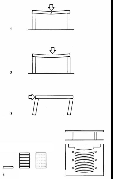
Strength, Stiffness, Stability, Synergy
Structures must be designed to satisfy three Ss and should satisfy all four Ss of structural design – as demonstrated on the following examples, illustrated at left.
1Strength to prevent breaking
2Stiffness to prevent excessive deformation
3Stability to prevent collapse
4Synergy to reinforce architectural design, described on two examples:
Pragmatic example: Beam composed of wooden boards
Philosophical example: Auditorium design
Comparing beams of wooden boards, b = 12” wide and d = 1”deep, each. Stiffness is defined by the Moment of Inertia, I = b d3/12
1 board, I = 12x13/12 |
I = 1 |
10 boards I = 10 (12x13/12) |
I = 10 |
10 boards glued, I = 12x103/12 |
I = 1000 |
Strength is defined by the Section modulus, S = I/(d/2) |
|
1 board, S = 1/o.5 |
S = 2 |
10 boards, S = 10/0.5 |
S = 20 |
10 boards, glued, S =1000/5 |
S = 200 |
Note:
The same amount of material is 100 times stiffer and 10 times stronger when glued together to transfer shear and thereby engage top and bottom fibers in compression and tension (a system, greater than the sum of its parts). On a philosophical level, structures can strengthen architectural design as shown on the example of an auditorium:
•Architecturally, columns define the circulation
•Structurally, column location reduces bending in roof beams over 500% !
3-2 BACKGROUND Basic Concepts
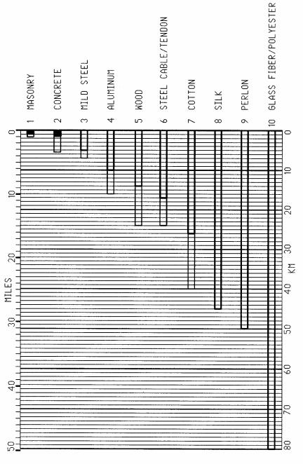
Rupture length
Rupture length is the maximum length a bar of constant cross section area can be suspended without rupture under its weight in tension (compression for concrete & masonry).
Rapture length defines material efficiency as strength / weight ratio:
R = F / λ
R = rupture length
F = breaking strength
λ = specific gravity (self weight)
Rupture length, is of particular importance for long-span structures. The depth of horizontal span members increases with span. Consequently the weight also increases with span. Therefore the capacity of material to span depends on both its strength and weight. This is why lightweight material, such as glass fiber fabrics are good for longspan structures. For some material, a thin line extends the rupture length to account for different material grades.
The graph data is partly based on a study of the Light weight Structures Institute, University Stuttgart, Germany
3-3 BACKGROUND Basic Concepts