

Architectural Structures
.pdf6
Bending
Bending elements are very common in structures, most notably as beams. Therefore, the theory of bending is also referred to as beam theory, not only because beams are the most common bending elements but their form is most convenient to derive and describe the theory. For convenience, similar elements, such as joists and girders, are also considered beams. Although they are different in the order or hierarchy of structures, their bending behavior is similar to that of beams, so is that of other bending elements, such as slabs, etc., shown on the next page. Thus, although the following description applies to the other bending elements, the beam analogy is used for convenience.
Beams are subject to load that acts usually perpendicular to the long axis but is carried in bending along the long axis to vertical supports. Under gravity load beams are subject to bending moments that shorten the top in compression and elongate the bottom in tension. Most beams are also subject to shear, a sliding force, that acts both horizontally and vertically. Because beams and other bending elements are very common, the beam theory is important in structural design and analysis.
As for other structural elements, beam investigation may involve analysis or design; analysis, if a given beam is defined by architectural or other factors; design, if beam dimensions must be determined to support applied loads within allowable stress and deflection. Both, analysis and design, require to find the tributary load, reactions, shear, and bending moment. In addition, analysis requires to find deflections, shearand bending stress, and verify if they meet allowable limits; by contrast design requires sizing the beam, usually starting with an estimated size.
The following notations are commonly used for bending and shear stress:
fb= actual bending stress |
Fb= allowable bending stress |
fv= actual shear stress |
Fv= allowable shear stress |
Allowable stresses are given in building codes for various materials. Allowable stresses assumed in this chapter are:
Wood |
|
Fb= 1450 psi (9998 kPa) |
Fv= 95 psi (655 kPa) |
Steel |
|
Fb= 22 ksi (152 MPa) |
Fv= 14 ksi (97 MPa) |
The more complex design and analysis of concrete and masonry will be introduces-later.
6-1 FUNDAMENTALS: Bending
Bending and Shear
Although derivation and numeric examples are required to analyze and design beams, intuitive understanding is an important prerequisite to gain deeper insight into the behavior of beams. The following is an intuitive introduction to beam bending and shear. A simple beam with uniform load is used for convenience.
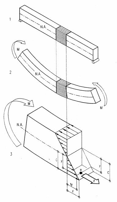
Bending moment
Gravity load on a simple beam shortens the top and elongates the bottom, causing compressive and tensile stresses at top and bottom, respectively; with zero stress at the neutral axis (N. A.). In beams of symmetrical cross-section, the neutral axis is at the center. The compressive and tensile stress blocks generate an internal force couple that resists the external bending moment caused by load.
1Simple beam with pin and roller supports
2Deformed beam under uniform gravity load
3Free-body diagram with bending stress block that generates an internal force couple to resist the external bending moment caused by load
6-4 FUNDAMENTALS: Bending
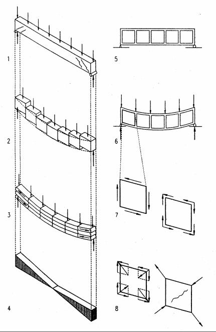
Shear force
With few exceptions, described later, shear coexists with bending. When shear is present it acts both horizontally and vertically at equal magnitude. In wood beams horizontal shear is more critical because wood’s shear capacity is much smaller parallel than perpendicular to the grain.
1Beam under uniform load with shear cracks as they occur in some concrete beams near the supports where shear is maximum
2Tendency of beam parts to slide vertically generates vertical shear stress that is zero at mid-span and increases to maximum at the supports where the vertical shear deformation is greatest
3Tendency of beam layers to slide horizontally generates horizontal shear that is zero at mid-span and increases toward the supports. This is visualized, assuming a beam composed of several boards
4Shear diagram reflects shear distribution over beam length
5Unloaded beam marked with squares to visualize shear
6Loaded beam with squares deformed into rhomboids due to shear
7Horizontal and vertical shear couples on a square beam part are equal to balance rotational tendencies (ΣM = 0). Therefore, horizontal and vertical shear stresses are equal at any point on the beam.
8Shear vectors generate compression and tension diagonal to the shear. This tends to generate diagonal tension cracks in concrete beams
6-5 FUNDAMENTALS: Bending
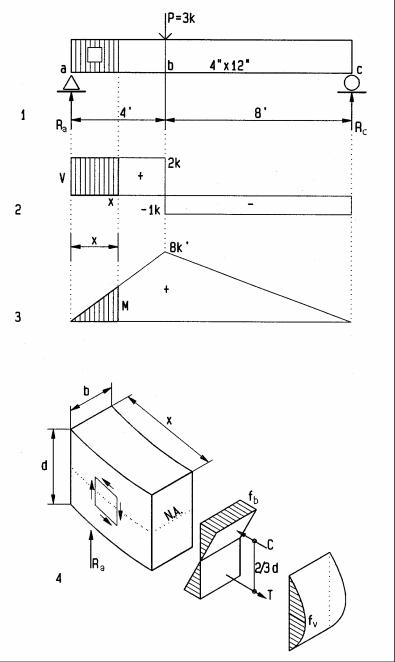
Bending and shear stress
Bending and shear stresses in beams relate to bending moment and shear force similar to the way axial stress relates to axial force (f = P/A). Bending and shear stresses are derived here for a rectangular beam of homogeneous material (beam of constant property). A general derivation follows later with the Flexure Formula.
1Simple wood beam with hatched area and square marked for inquiry
2Shear diagram with hatched area marked for inquiry
3Bending moment diagram with hatched area marked for inquiry
4Partial beam of length x, with stress blocks for bending fb and shear fv, where x is assumed a differential (very small) length
Reactions, found by equilibrium ΣM = 0 (clockwise +) |
|
||
at c: |
+12 Ra-3(8)=0; Ra=3(8)/12 |
|
Ra = 2 k |
at a: -12 Rc+3(4)=0; Rc=3(4)/12 |
|
Rc = 1 k |
|
Shear V, found by vertical equilibrium, ΣV=0 (upward +). |
V = 2 k |
||
right of a and left of b |
V= 0+2 |
||
right of b and left of c |
V= 2-3 |
V = -1 k |
|
Bending moment M, found by equilibrium ΣM=0 (clockwise +) |
|
||
at a: |
M = +2(0) |
|
M = 0 k’ |
at b: |
M = +2(4) |
|
M = 8 k’ |
at c: |
M = +2(12)-3(8) |
|
M = 0 k’ |
Bending stress fb is derived, referring to 4. Bending is resisted by the force couple C-T, with lever arm 2/3 d = distance between centroids of triangular stress blocks. C=T= fb bd/4, M= C(2d/3) = (fbbd/4)(2d/3) = fbbd2/6, or
fb= M/(bd2/6); where bd2/6 = S= Section Modulus for rectangular beam; thus fb= M/S
For our beam: |
S= bd2/6= 4(12)2/6= |
S = 96 in3 |
|
fb= M/S= 8(1000)12/96 * |
fb = 1000 psi |
* multiplying by 1000 converts kips to pounds, by 12 converts feet to inches.
Shear stress fv is derived, referring to 4. Bending stress blocks pushing and pulling in opposite directions create horizontal shear stress. The maximum shear stress is fv=C/bx, where b = width and x = length of resisting shear plane. Shear at left support is V = R. Let M = bending moment at x, and fb= bending stress at x, then M = RX = VX, and fb=M/S=Vx/S. Substituting Vx/S for fb in C = fbbd/4, the compressive top force, yields C=(Vx/S)(bd/4). Thus fv=C/(bx) yields fv=(Vx/S)(bd/4)/(bx). Substituting bd2/6 for S yields
fv = |
Vx bd / 4 |
Vbd / 4 |
|
6V |
, or |
|
|
bx |
= b2d 2 / 6 |
= |
|
||
bd 2 / 6 |
4bd |
|||||
fv = 1.5 V / bd
For the sample beam: |
fv = 1.5(2)1000/(4x12) |
fv = 63 psi |
6-7 FUNDAMENTALS: |
Bending |
|
Equilibrium Method
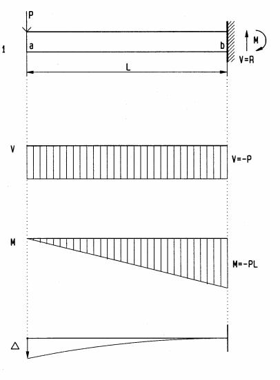
Cantilever beam with point load
Assume a beam of length L = 10 ft, supporting a load P = 2 k. The beam bending moment and shear force may be computed, like the external reactions, by equations of equilibrium ΣH=0, ΣV= 0, and ΣM=0. Bending moment and shear force cause bendingand shear stress, similar to axial load yielding axial stress f= P/A. Formulas for bendingand shear stress are given on the next page and derived later in this chapter.
1 Cantilever beam with concentrated load
V Shear diagram (shear force at any point along beam)
M Bending moment diagram (bending moment at any point along beam)
∆Deflection diagram (exaggerated for clarity)
Reactions, found by equilibrium, ΣV=0 (up +) and ΣM=0 (clockwise +)
at b ΣV= 0 = |
R–2= 0 |
R = 2 k |
at b ΣM= 0 = |
M–2(10)= 0 |
M = 20 k’ |
Shear V, found by vertical equilibrium, ΣV=0 (up +) |
|
|
right of a = left of b |
V= 0-2 |
V = - 2 k |
Left of a and right of b, shear is zero because there is no beam to resist it (reaction at b reduces shear to zero). Shear may be checked, considering it starts and stops with zero. Concentrated loads or reactions change shear from left to right of them. Without load between a and b (beam DL assumed negligible) shear is constant.
Bending moment M, found by moment equilibrium, ΣM=0 (clockwise +)
at a |
M = -2(0) |
= 0 k’ |
at mid-span M = -2(5) |
= -10 k’ |
|
at b |
M = -2(10) |
= -20 k’ |
The mid-span moment being half the moment at b implies linear distribution. The support reaction moment is equal and opposite to the beam moment.
Deflection ∆ is described later. Diagrams visualize positive and negative bending by concave and convex curvature, respectively. They are drawn, visualizing a highly flexible beam, and may be used to verify bending.
6-8 FUNDAMENTALS: Bending
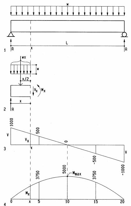
Simple beam with uniform load
1Beam of L= 20 ft span, with uniformly distributed load w = 100 plf
2Free-body diagram of partial beam x units long
3Shear diagram
4Bending moment diagram
To find the distribution of shear and bending along the beam, we investigate the beam at intervals of 5’, from left to right. This is not normally required.
Reactions R are half the load on each support due to symmetry
R= w L/2 = 100 (20)/2 |
R= +1000 lbs |
|
Shear force Vx at any distance x from left is found using ∑ V = 0 |
||
∑ V = 0; R - w x - Vx = 0; |
solving for Vx |
|
Vx = R - w x |
|
|
at x = 0’ |
V = 0 + Ra = 0 +1000 |
V = +1000 lbs |
at x = 5’ |
V = + 1000 - 100 (5) |
V = +500 lbs |
at x = 10’ |
V = + 1000 - 100 (10) |
V = 0 lbs |
at x = 15’ |
V = + 1000 - 100 (15) |
V = -500 lbs |
at x = 20’ |
V = + 1000 - 100 (20) |
V = -1000 lbs |
Bending moment Mx at any distance x from left is found by ∑ M = 0. |
||
∑ M = 0; R x – w x (x/2) - Mx = 0; |
solving for Mx |
|
Mx = R x - w x2/2 |
|
|
at x = 0 |
M = 1000 (0) - 100 (0)2/2 |
M = 0 lb-ft |
at x = 5’ |
M = 1000 (5) - 100 (5)2/2 |
M = 3750 lb-ft |
at x = 10’ |
M = 1000 (10)-100 (10)2/2 |
M = 5000 lb-ft |
at x = 15’ |
M = 1000 (15)-100 (15)2/2 |
M = 3750 lb-ft |
at x = 20’ |
M = 1000 (20)-100 (20)2/2 |
M = 0 lb-ft |
Bending is zero at both supports since pins and rollers have no moment resistance. Since the bending formula Mx= Rx-wx2/2 is quadratic, bending increase is quadratic (parabolic curve) toward maximum at center, and decreases to zero at the right support. For simple beams with uniform load the maximum shear force is at the supports and the maximum bending moment at mid-span (x= L/2) are:
Vmax = R = w L / 2
Mmax = (wL/2)L/2 – (wL/2)L/4 = 2wL2/8 - wL2/8, or
Mmax = wL2 / 8
This formula is only for simple beams with uniform load. Verifying example:
Mmax= wL2/8 = 100(20)2/8 |
Mmax= +5000 lbs-ft |
(same as above) |
6-9 FUNDAMENTALS: |
Bending |
|
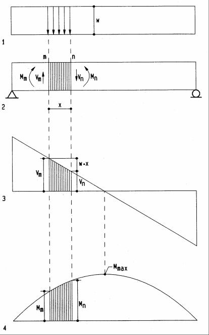
Area Method
The area method for beam design simplifies computation of shear forces and bending moments and is derived, referring to the following diagrams:
1Load diagram on beam
2Beam diagram
3Shear diagram
4Bending diagram
The area method may be stated:
•The shear at any point n is equal to the shear at point m plus the area of the load diagram between m and n.
•The bending moment at any point n is equal to the moment at point m plus the area of the shear diagram between m and n.
The shear force is derived using vertical equilibrium:
∑ V = 0; Vm - w x - Vn = 0; |
solving for Vn |
Vn = Vm-wx
where w x is the load area between m and n (downward load w = negative). The bending moment is derived using moment equilibrium:
∑ M = 0; Mm + Vmx – w x x/2 - Mn = 0; solving for M n
Mn = Mm+Vmx-wx2/2
where Vmx – wx2/2 is the shear area between m and n, namely, the rectangle Vm x less the triangle w x2/2. This relationship may also be stated as
Mn = Mm + Vx, where V is the average shear between m and n.
By the area method moments are usually equal to the area of one or more rectangles and/or triangles. It is best to first compute and draw the shear diagram and then compute the moments as the area of the shear diagram.
From the diagrams and derivation we may conclude:
•Positive shear implies increasing bending moment.
•Zero shear (change from + to -) implies peak bending moment (useful to locate maximum bending moment).
•Negative shear implies decreasing bending moment.
Even though the forgoing is for uniform load, it applies to concentrated load and nonuniform load as well. The derivation for such loads is similar.
6-10 FUNDAMENTALS: Bending
Examples
The following wood beams demonstrate the area method for design and analysis. For design, a beam is sized for given loads; for analysis, stresses are checked against allowable limits, or how much load a beam can carry.
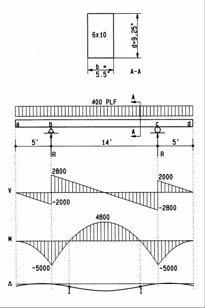
Beam design
V Shear diagram. M Bending diagram.
∆Deflection diagram.
I Inflection point (change from + to - bending).
Reactions |
|
|
|
R= 400plf (24)/2 |
R = 4800 lbs |
Shear |
|
|
Va = 0 |
Va = 0 lbs |
|
Vbl = 0 -400(5) |
Vbl = -2000 lbs |
|
Vbr = -2000 + 4800 |
Vbr = +2800 lbs |
|
Vcl = +2800 - 400(14) |
Vc l= -2800 lbs |
|
Vcr = -2800 + 4800 |
Vcr = +2000 lbs |
|
Vd = +2000 - 400(5) |
Vd = 0 lbs, ok |
|
Moment |
|
|
Ma |
= 0 |
Mb = -5000 lb-ft |
Mb |
= 0 -2000 (5)/2 |
|
Mb-c = -5000+ 2800 (7)/2 |
Mb-c = +4800 lb-ft |
|
Mc |
= +4800 - 2800 (7)/2 |
Mc = -5000 lb-ft |
Md |
= - 5000+ 2000 (5)/2 |
Md = 0, ok |
Try 4x10 beam |
|
|
S= (3.5) 9.252/6 |
S = 50 in3 |
|
Bending stress |
|
|
f b = Mmax/S= 5000 (12)/50 |
f b = 1200 psi |
|
|
|
1200 < 1450, ok |
Shear stress |
|
|
f v = 1.5V/bd=1.5(2800)/[3.5(9.25)] |
f v = 130 psi |
|
|
|
130 > 95, not ok |
Try 6x10 beam |
|
|
f v = 1.5V/bd=1.5 (2800)/[5.5 (9.25)] |
f v= 83 psi |
|
|
|
83 < 95, ok |
Note: increased beam width is most effective to reduce shear stress; but increased depth is most effective to reduce bending stress.
6-11 FUNDAMENTALS: Bending
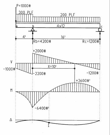
Beam analysis |
|
Reactions |
|
Σ Mc = 0 = +16 Rb - 1000 (20) - 300 (4) 18 - 200 (16) 8 |
|
16 Rb = 1000(20) + 300 (4) 18 + 200 (16) 8 |
|
Rb = (20000 + 21600 + 25600)/16 |
Rb = +4200 lbs |
Σ Mb = 0 = -16 Rc -1000(4) - 300(4)2 + 200(16)8 |
|
16 Rc = -1000(4) - 300(4)2 + 200(16) 8 |
|
Rc = (-4000 -2400 + 25600)/16 = |
Rc = +1200 lbs |
Shear |
|
Var = 0 - 1000 |
Var= -1000 lbs |
Vbl = -1000 - 300 (4) |
Vbl = -2200 lbs |
Vbr = -2200 + 4200 |
Vbr= +2000 lbs |
Vcl = +2000 - 200(16) = -Rc |
Vcl= -1200 lbs |
Vcr = -1200 + 1200 |
Vcr= 0 lbs |
Find x, where shear = 0 and bending = maximum: |
|
Vbr-w2 x = 0; x = Vbr/w2 = 2000/200 |
x = 10 ft |
Moment |
|
Ma = 0 |
Mb = -6400 lb-ft |
Mb = 0 + 4 (-1000 -2200)/2 |
|
Mx = -6400 + 10 (2000)/2 |
Mx = +3600 lb-ft |
Mc = +3600 + (16-10)(-1200)/2 |
Mc = 0 |
Section modulus |
|
S = bd2/6 = (3.5)11.252/6 |
S = 74 in3 |
Bending stress |
|
f b = M/S= 6400(12)/74 |
f b = 1038 psi |
|
1038 < 1450, ok |
Shear stress |
|
fv = 1.5V/(bd) = 1.5(2200)/[3.5(11.25)] |
f v = 84 psi |
|
84 < 95 = ok |
Note: stress is figured, using absolute maximum bending and shear, regardless if positive or negative. Lumber sizes are nominal, yet actual sizes are used for computation. Actual sizes are ½ in. less for lumber up to 6 in. nominal and ¾ in. less for larger sizes: 4x8 nominal is 3½x7¼ in. actual.
Note: in the above two beams shear stress is more critical (closer to the allowable stress) than bending stress, because negative cantilever moments partly reduces positive moments.
6-12 FUNDAMENTALS: Bending
Indeterminate beams
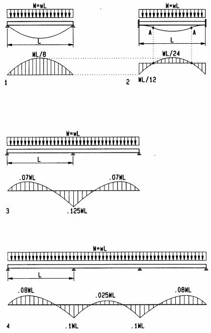
Indeterminate beams include beams with fixed-end (moment resistant) supports and beams of more than two supports, referred to as continuous beams. The design of statically indeterminate beams cannot be done by static equations alone. However, bending coefficients, derived by mechanics, may be used for analysis of typical beams. The bending moment is computed, multiplying the bending coefficients by the total load W and span L between supports. For continuous beams, the method is limited to beams of equal spans for all bays. The coefficients here assume all bays are loaded. Coefficients for alternating live load on some bays and combined dead load plus live load on others, which may result in greater bending moments, are in Appendix A. Appendix A also has coefficients for other load conditions, such as various point loads. The equation for bending moments by bending coefficients is:
M = C L W
M = bending moment C = bending coefficient
L = span between supports W = w L (total load per bay)
w = uniform load in plf (pounds / linear foot
1Simple beam
2Fixed-end beam
(combined positive plus negative moments equal the simple-beam moment)
3Two-span beam
4Three-span beam
6-13 FUNDAMENTALS: Bending