

Architectural Structures
.pdfCase studies
Skating Rink, Heerenveen, Holland
Architect: Van der Zee & Ybema
Engineer: Arie Krijegsman, ABT
Steel trusses
Allowable stress Fy = 36 ksi x 0,6
Truss span L= 66m/0.3048
Truss spacing e =7.2m/.3048
Truss depth at mid span d = 5.8m/0.3048
DL |
= |
o.6 kPa |
(12.5 psf) |
LL |
= |
0.5 kPa |
(10.4 psf) |
Σ |
= |
1.1 kPa |
(22.9 psf) |
Uniform load per truss w = 24’ x 22.9 psf / 1000
Mid span point load (center truss, A transfers load of circular end units) Tributary area of end units
A = π r2/3 = π(217’/2)2/3 Point load per truss
P = 12,278 x 22.9 psf / 1000 / 16 trusses Global moment
M = PL/4+wL2/8 = 18x217/4 + 0.55 x 2172/8 Chord bar force
C = T = M/d = 4,214 / 19 Bottom tension chord Try wide flange section Try wide flange
Allowable force P from AISC table (use L = 0’ for tension, no buckling) Pall = 222
Top chord un-braced length L = 217’/12
Top chord bending (negative support bending M = w L2/12 = 0.55 x 182 / 12
Try W12x50
A = 14.7in2, Ix= 394 in4, rx= 5.17” (y-axis is braced by roof deck) Bending stress
fb = M c / I = 15k’x12”x 6”/394
Axial stress fa = C / A = 222 k /14.7 in2 Slenderness KL/rx = 1x18’x12” / 5.17” Allowable buckling stress (from AISC table) Check combined stress fa/Fa + fb/Fb <=1 fa/Fa + fb/Fb = 15.1/19 + 2.74 / 21.6 = 0.92 Use
Fa = 21.6 ksi L = 217’ e = 24’ d = 19’
w = 0.55 klf
A = 12,278 sq. ft.
P = 18 k
M = 4,214 k’
C =T = 222 k
W8x35
222 = 222, ok L = 18’
M = 15 k’
fb = 2.74 ksi fa = 15.1 ksi kL/r = 42 Fa =19 ksi
0.92 < 1, ok W12x50
10-7 DESIGN METHODS Conceptual Design
ExhibitHall 26 Hanover
Architect: Thomas Herzog
Engineer: Schlaich Bergermann
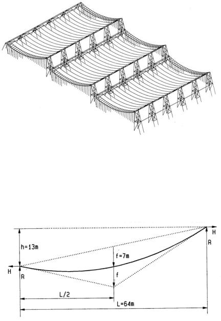
Given
Steel suspender bands 30x400 mm (1.2x16”), spaced 5.5 m (18’)
LL = |
0.5 kN/m2 |
(10 psf) |
|
DL = |
1.2 kN/m2 |
(25 psf) |
|
Σ = |
1.7 kN/m2 |
(35 psf) |
|
Uniform load |
|
w = 1.7 kN/m2 x 5.5 m = |
w = 9.35 kN/m |
Global moment |
|
M = w L2 / 8 = 9.35 x 642 / 8 |
M = 4787 kN-m |
Horizontal reaction |
|
H = M / f = 4787 / 7 |
H = 684 kN |
Vertical reaction R (max.)
Reactions are unequal; use R/H ratio (similar triangles) to compute max. R R/H = (2f+h/2) / (L/2), hence
R = H (2f+h/2) / (L/2) = 684 (2x7+13/2) / (64/2) |
438 kN |
Suspender tension (max.) |
|
T = (H2 + R2)1/2 = (684 2 + 438 2 )1/2 |
T = 812 kN |
Suspender stress (A = 30x400 mm) |
|
f = T / A = 1000x812 / (30x400) |
f = 67.7 MPa |
US unit equivalent |
|
67.7 kPa x 0.145 |
f = 9.8 ksi |
|
9.8 < 22 ksi, ok |
Graphic method
•Draw a vector of the total vertical load
•Equilibrium vectors parallel to support tangents give cable forces
•Equilibrium vectors at supports give H and R reactions.
Note: The unequal support height is a structural disadvantage since the horizontal reactions of adjacent bays don’t balance, but it provides lighting and ventilation, a major objective for sustainability. The roof consists of prefab wood panels, filled with gravel to resist wind uplift. Curtain wall mullions at the roof edge are prestressed between roof and footing to prevent buckling under roof deflection. In width direction the roof is slightly convex for drainage; which also gives the interior roof line a pleasing spatial form.
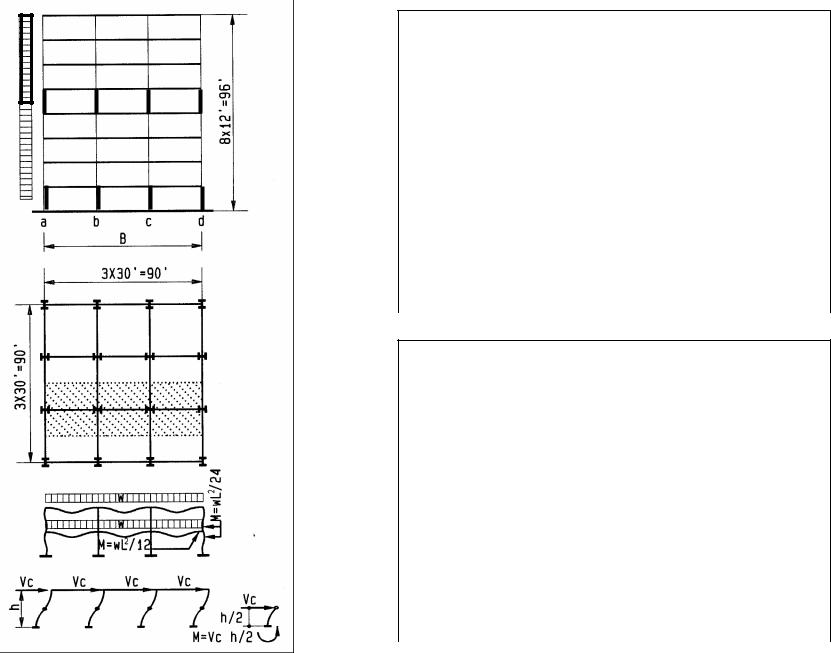
10-8 DESIGN METHODS Conceptual Design
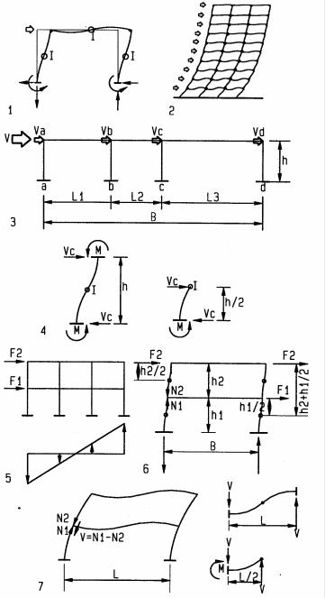
Portal method
The Portal Method for rough moment frame design is based on these assumptions:
•Lateral forces resisted by frame action
•Inflection points at mid-height of columns
•Inflection points at mid-span of beams
•Column shear is based on tributary area
•Overturn is resisted by exterior columns only
1Single moment frame (portal)
2Multistory moment frame
3Column shear is total shear V distributed proportional to tributary area: Va = (V/B) L1 / 2
Vb = (V/B) (L1+L2) / 2 Vc = (V/B) (L2+L3) / 2 Vd = (V/B) L3 / 2
4Column moment = column shear x height to inflection point Ma = Va h / 2
Mb = Vb h / 2 Mc = Vc h / 2 Md = Vd h / 2
5Exterior columns resist most overturn, the portal method assumes they resist all
6Overturn moments per level are the sum of forces above the level times lever arm
of each force to the column inflection point at the respective level:
M2 |
= F2 h2 / 2 |
(level 2) |
M1 |
= F2 (h2+h1 / 2) + F1 h1 / 2 |
(level 1) |
Column axial force = overturn moment divided by width B
N = M / B
Column axial force per level: |
|
N2 = M2 / B |
(level 2) |
N1 = M1 / B |
(level 1) |
7Beam shear = column axial force below beam minus column axial force above beam Level 1 beam shear:
V = N1 - N2 Roof beam:
V = N2 - 0 = N2
Beam bending = beam shear times distance to inflection point at beam center M = V L / 2
Beam axial force is negligible and assumed 0
10-15 DESIGN METHODS Conceptual Design
Example: 2-story building
Assume:
L1 = 30’
L2 = 20’
B = 30+20+30 = 80’ h = h1 = h2 = h = 14’ F1 = 8 k
F2 = 12 k
1st floor |
|
Base shear |
|
V = F1+F2 = 8+12 |
V = 20 k |
Column shear |
|
Va = (L1/2) (V/B) = 15’x20/80 |
Va = 3.75 k |
Vb = (L1+L2)/2 (V/B) = (20+30)/2 (20/80) |
Vb = 6.25 k |
Column bending |
|
Ma = Va h/2 = 3.75 x 14/2 |
Ma = 26 k’ |
Mb = Vb h/2 = 6.25 x 14/2 |
Mb = 44 k’ |
Overturn moments |
|
M1 = F2 (h2+h1/2)+F1 h1/2 = 12 (14+7)+8x7 |
M1 = 308 k |
M2 = F2 h2/2 = 12x7 |
M2 = 84 k’ |
Column axial load 1st floor |
|
N1 = M1/B = 308/80 |
N1 = 3.9 k |
Column axial load 2nd floor |
|
N2 = M2/B = 84/80 |
N2 = 1.1 k |
Beam shear |
|
V1 = N1–N2 = 3.9-1.1 |
V1 = 2.8 k |
Beam bending |
|
M1 = V1 L1/2 = 2.8x30/2 |
M1 = 42 k’ |
M2 = V1 L2/2 = 2.8x20/2 |
M2 = 28 k’ |
2nd floor |
|
2nd floor shear |
|
V = F2 |
V = 12 k |
Column a shear |
|
Va = (L1/2) (V/B)=15’x12/80 |
Va = 2.25 k |
Column b shear |
|
Vb = (L1+L2)/2 (V/B) = (30+20)/2x12/80 |
Vb = 3.75 k |
Column a bending |
|
Ma = Va h/2 = 2.25 x 14/2 |
Ma = 15.75 k’ |
Column b bending |
|
Mb = Vb h/2 = 3.75 x 14/2 |
Mb = 26.25 k’ |
Overturn moment |
|
M2 = F2xh/2 = 12x14/2 |
M2 = 84 k’ |
Column axial load |
|
N2 = M2/B = 84/80 |
N2 = 1.0 k |
Beam shear |
|
V2 = N2 |
V2 = 1.0 k |
Beam 1 bending |
|
M1 = V2 L1/2=1.0x30/2 |
M1 = 15 k’ |
Beam 2 bending |
|
M2 = V2 L2/2=1.0x20/2 |
M2 = 10 k’ |
10-16 DESIGN METHODS Conceptual Design
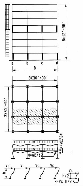
Moment frame
Eight story steel moment frame, high strength steel, Fy = 50 ksi Fa = Fb = 30 ksi Live load 50 psf, load reduction R in percent per IBC
R = 0.08 (A-150) A = tributary area
Max. reduction: 40% for members supporting a single level, 60% for other members
Gravity load |
|
Beam (psf) |
Column (psf) |
Framing |
|
10 |
10 |
Concrete slab |
|
37 |
37 |
Partitions |
|
20 |
20 |
Floor / ceiling |
|
3 |
3 |
DL |
|
70 |
70 |
LL |
|
50 x 0.6 = 30 |
50 X 0.4 = 20 |
Total DL + LL |
|
100 |
90 |
Average wind pressure |
|
P = 33 psf |
|
Design ground floor and 4th floor |
|
||
Uniform beam load (shaded tributary are) |
|
||
W = 100 psf x 30’/1000 |
w = 3 klf |
||
Uniform column load (distributed on beam) |
|
||
w = 90 psf x 30’/1000 |
w = 2.7 klf |
||
Base shear |
|
|
|
V = 33 psf x 30’ x 7.5 x 12’/1000 |
V = 89 k |
||
Level 4 shear |
|
|
|
V = 33 psf x 30’ x 3.5 x 12’/1000 |
V = 42 k |
||
Overturn moments |
M0 = 33 psf x 30’ x (7.5x12)2 /2 / 1000 |
M0 = 4,010 k’ |
|
Ground floor |
|||
First floor |
M1 = 33 psf x 30’(6.5 x12)2 /2 / 1000 |
M1 =3,012 k’ |
|
Fourth floor |
M4 = 33 psf x 30’(3.5 x12)2 /2 / 1000 |
M4 = 873 k’ |
|
Beam design |
|
|
|
Column a & d axial load |
|
||
N0 = M0 / B = 4,010 / 90 |
N0 = 45 k |
||
N1 = M1 / B = 3,012 / 90 |
N1 = 34 k |
||
Beam design |
|
|
|
Beam shear |
|
|
|
V = N0 – N1 = 45-34 |
|
|
V = 11 k |
Beam bending |
|
|
|
M lateral = V L/2 = 11x30/2 |
M lateral = 165 k’ |
||
M gravity = wL2/12 = 3x302/12 |
M gravity = 225 k’ |
||
ΣM = 165 + 225 |
|
|
Σ M = 390 k’ |
Required Sx = M / Fb = 12”x390 k’/ 30 ksi |
Sx = 156 in3 |
||
Use W18x86 |
|
|
Sx = 166 > 156 |
Note: W18 beam has optimal ratio L/d = 20 |
|
||
10-17 DESIGN METHODS Conceptual Design
Ground floor
Column shear
Column |
|
Vc = L tributary V / B |
|
|
|
Vc |
|
a & d |
|
|
15x89/90 |
|
|
|
14.8 k |
b & c |
|
|
30x89/90 |
|
|
|
29.7 k |
|
|
|
|
|
|
|
|
|
|
|
Column bending |
|
|
||
Column |
|
M lateral = Vc h/2 |
M gravity = wL2/24 |
|
|
ΣM |
|
a & d |
|
14.8 x12/2 = 89 k’ |
2.7x302/24 = 101 k’ |
|
|
190 k’ |
|
b & c |
|
29.7x12/2 = 178 k’ |
0 |
|
|
178 k’ |
|
|
|
|
Column axial |
force (n = # of stories) |
|
|
|
Column |
|
P lateral = Mo/B |
Pgravity = n w L tributary |
|
|
Σ P |
|
a & d |
|
4,010 / 90 = 45 k |
8x2.7x15 = 324 k |
|
|
369 k |
|
b & c |
|
0 |
8x2.7x30 = 648 k |
|
|
648 k |
|
|
Column axial force + bending |
(ΣP = P+M Bx, estimate |
Bx than verify) |
|
|||
Column |
|
P |
|
M Bx (convert M to k”) |
Σ P |
||
a & d |
|
365 k |
|
12”x190 k’x0.185 = 422 k |
787 k |
||
b & c |
|
648 k |
|
12”x178 k’x0.185 = 395 k |
1043 k |
||
|
|
Design column (assume KL = 1.2 x12 = 14’) |
|
|
|||
Column |
|
Use |
|
Check P allowable vs. P |
|
Check Bx estimate vs. Bx |
|
a & d |
|
W14x109 |
|
803 > 785, OK |
|
0.185 = 0.185, OK |
|
b & c |
|
W14x145 |
|
1090 > 1043, OK |
|
0.185 > 0.184, OK |
|
4th floor
Column shear
Column |
|
Vc = L tributary V / B |
|
|
|
Vc |
|
a & d |
|
|
15x42/90 |
|
|
|
7 k |
b & c |
|
|
30x42/90 |
|
|
|
14 k |
|
|
|
Column bending |
|
|
||
Column |
|
M lateral = Vc h/2 |
M gravity = wL2/24 |
|
|
Σ M |
|
a & d |
|
7 x12/2 = 42 k’ |
2.7x302/24 = 101 k’ |
|
|
143 k’ |
|
b & c |
|
14x12/2 = 84 k’ |
0 |
|
|
84 k’ |
|
|
|
|
Column axial |
force (n = # of stories) |
|
|
|
Column |
|
P lateral = Mo/B |
P gravity = nwL tributary |
|
|
Σ P |
|
a & d |
|
873/90 = 10 k |
4x2.7x15 = 162 k |
|
|
172 k |
|
b & c |
|
0 |
4x2.7x30 = 324 k |
|
|
324 k |
|
|
Column axial force + bending |
(ΣP = P+M Bx, estimate |
Bx than verify) |
|
|||
Column |
|
P |
|
M Bx (convert M to k”) |
Σ P |
||
a & d |
|
172 k |
|
12”x143 k’x0.196 = 336 k |
508 k |
||
b & c |
|
324 k |
|
12”x84 k’x0.196 = 198 k |
522 k |
||
|
|
Design column (assume KL = 1.2 x12 = 14’) |
|
|
|||
Column |
|
Use |
|
Check P allowable vs. P |
|
Check Bx estimate vs. Bx |
|
a & d |
|
W14x82 |
|
515 > 508, OK |
|
0.196 = 0.196, OK |
|
b & c |
|
W14x90 |
|
664 > 522, OK |
|
0.196 > 0.185, OK |
|
10-18 DESIGN METHODS Conceptual Design
Test models
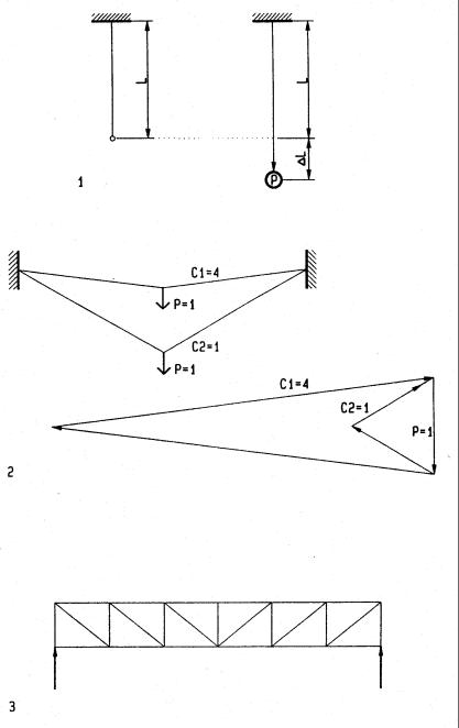
Static models are useful to test structures for strength, stiffness, and stability. They may have axial resistance (truss), bending resistance (beam), or both axial and bending resistance (moment frame). Static models have three scales: geometric scale, force scale, and strain scale. The geometric scale relates model dimensions to original dimensions, such as 1:100. The force scale relates model forces to the original structure. For a force scale of 1:100 one pound in the model implies 100 pounds in the original structure. The force scale should be chosen to keep model forces reasonable (usually under 50 pounds). The strain scale relates model strain (deformation) to strain in the original structure. A strain scale of 1:1 implies model strain relates to original strain in the geometric scale; given a geometric scale of 1:10 a model strain of 1 inch implies 10 inch original strain. For structures with small deformations may a strain scale of 5:1, for example, helps to visualize strain. However, structures with large strain like membranes, require a strain scale of 1:1 to avoid errors (see 2). Scales are defined as:
Geometric Scale: SG = Lm/Lo = model dimension / original dimension Force Scale: SF = Pm/Po = model force / original force
Strain Scale: SS = εm/εm = model strain / original strain The derivation for axial and bending resistance models assumes:
A = Cross-section area E = Modulus of elasticity I = Moment of inertia
k = Constant of integration for deflection; for cantilever beams with point load ∆ = kPL3 / (EI) where k = 1/3
m = Subscript for model
o = Subscript for original structure
Axial resistance
Unit Strain ε = ∆L/L |
∆L = P L / (AE) |
hence |
Force P = A E ∆L/L = A E ε |
|
hence |
Force Scale = SF = Pm/Po = AmEm / (AoEo) εm/εo |
since εm/εo = SS |
|
SF = AmEm/(AoEo) SS |
|
|
SF = AmEm/(AoEo) |
if SS = 1 |
|
SF = Am/Ao = SG2 |
if = Em=Eo |
|
1Axial strain ∆L = P L/(AE); unit strain ε = ∆L/L
2Structures with large deformations, such as membranes, yield errors if the strain scale SS is not 1:1; as demonstrated in the force polygon
3Structures like trusses, with small deformations, may require a strain scale SS >1 to better visualize deformations.
10-21 DESIGN METHODS Conceptual Design
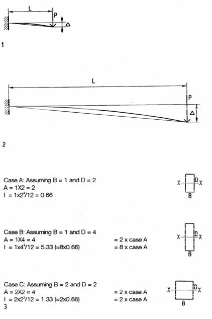
Bending resistance
Unit Strain ε = ∆/L |
∆ = kPL3 / (EI) |
hence |
Force P = EI∆ / (kL3) = EI / (kL2) ∆/L |
|
hence |
Force Scale SF = Pm/Po = [EmIm / (EoIo)] |
ko/km Lo2/Lm2 εm/εo |
|
Since the model and original have the same load and support conditions the constants of integration km = ko, hence the term ko/km may be eliminated. The term Lo2/Lm2 = 1/SG2 = 1/geometric scale squared, and εm/εo = SS = strain scale. Therefore the force scale is:
SF = EmIm/(EoIo) 1/SG2 SS
SF = EmIm/(EoIo) 1/SG2 |
If SS =1 |
SF = Im/Io 1/SG2 |
If Em = Eo, or simplified |
SF = SG2 |
assuming all model dimensions, |
|
including details, relate to the original in the geometric scale |
In the simplest form the force scale is equal to the geometric scale squared for both axial and bending resistant models. Thus a model with a geometric scale of 1:100 has a force scale of 1:10,000 if it is made of the same material or modulus of elasticity as the original structure.
Combined axial and bending resistance
Models with both axial and bending resistance, such as moment frames, should be of the same material or elastic modulus as the original in order to avoid errors. Referring to diagrams 3, if, for example, the elastic modulus of a model is half as much as in the original structure and the cross-section area is doubled to compensate for it, then the moment of inertia is four times greater, assuming area increase is perpendicular to the bending axis. For small adjustments this can be avoided by increasing the area parallel to the bending axis. Large differences in stiffness, such as wood simulating steel, with an elastic modulus about 20 times greater, are not possible. In such a case the strain scale could be 20:1 to amplify deflection rather than adjusting the cross-section area.
1 |
Model strain ε = ∆/L must be equal to the original strain. |
|
|
∆ = k PL3/EI |
where k = 1/3 |
2 |
Original strain ε = ∆/L |
|
|
∆ = k PL3/EI |
where k=1/3 |
Since k is the same in the model as in the original, for equal load and support conditions, it may be eliminated from the force scale equation
3Correlation between cross-section area A and moment of inertia I
demonstrates incompatibility between A and I since they increase at different rates, unless the increase is only in width direction
10-22 DESIGN METHODS Conceptual Design
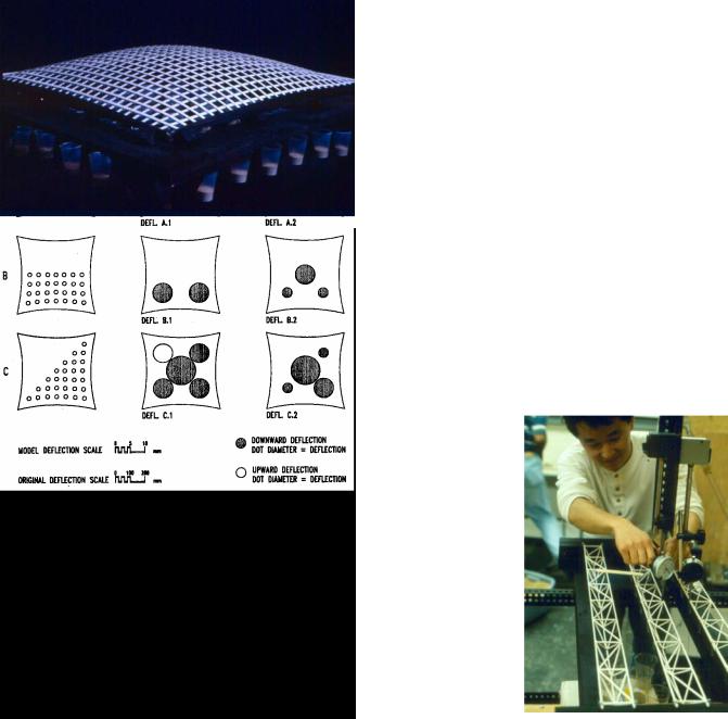
Test stand
•Light gauge steel frame 3’x5’
•Frame to support test models
•Adjustable platform for loads below the test model (crank mechanism lowers platform to apply load)
•Blocking deice holds load platform at any position
•Support frame for measure gauges above test model
Test procedure
•Position model with open base to allow loads below
•Suspend load cups filled with lead or sand from model (support loads on load platform before loading)
•Attach measure gauges above model
•Lower load platform with crank to apply load
•Measure deformations and stress
•Apply alternate loads (half load, etc.)
•Record deformations and stresses for all load conditions
Note
•Apply loads briefly to avoid creep deformation
•Apply loads gradually to avoid rupture
•Test all load conditions that may cause critical deformation or stress
•Adjust design if deformation or stress exceeds acceptable limits
10-23 DESIGN METHODS Conceptual Design
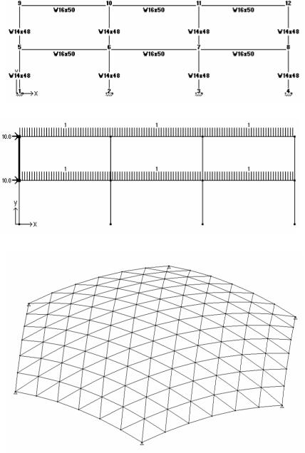
Moment frame(with joint numbers and member names)
Load diagram (uniform beam load, lateral point load)
Hexagonal grid shell dome
Computer aided design
Advance in computer technology made structural design and analysis widely available. The theory and algorithm of structural design programs is beyond the scope of this book. However, a brief introduction clarifies their potential and use.
Structure programs generate and solve a stiffness matrix of the structure. Based on the degree of freedom of joints, the output provides stress and strain. A two-dimensional truss with pin joints has two degrees of freedom and thus two unknowns per joint, X and Y-displacement. A three-d truss has three unknowns per joint. Two-D frames have four unknowns, X, Y-displacement and X, Y-rotation, but three-D frames have six unknowns per joint, X, Y, Z-displacement and X,Y, Z-rotation.
The structure input is defined by joints, members connecting the joints and loads. Joints of three-d structures are defined by X, Y, Z-coordinates, joint type (pin or moment joint), and degree of freedom, regarding X, Y Z-displacement and X, Y, Z-rotation (joints attached to the ground are fixed with pin or moment joints). Members are defined by properties, cross section area, moment of inertia, and modulus of elasticity. Some members may have end release at one or both ends, to allow pin joints of braces to connect to moment joints of beam to column, for example. End releases are simulated by a dummy pin adjacent to the moment joint. The geometry of a structure may be defined in the analysis program or imported as DFX file from a CAD program. Loads are defined as distributed or point load. Gravity load is usually assigned as uniform beam load, yet lateral wind or seismic loads are usually assigned as point loads at each level.
Output includes force, stress, and deformation for members, joint displacement and rotation, as well as support reactions. Output may be in tables and / or graphic display. Graphic display provides better intuitive understanding an d is more convenient to use.
Some programs simulate non-linear material behavior and / or non-linear geometric behavior. For example, non-linear material may include plastic design of steel with nonlinear stress/strain relation in the plastic range. Non-linear geometric analysis is for structures with large displacements, such as cable or membrane structures. Non-linear analysis usually involves an iterative algorithm that converges after several iterations to a desired level of accuracy. Some programs include a prestress element to provide formfinding for membranes structures. Some programs provide dynamic analysis, sometimes referred too as 4-D analysis. Programs with advanced features provide greater versatility and accuracy, but they are usually more complex to use.
Multiframe-4D used for the demonstrations features 2-d and 3-d static and 4-d dynamic analysis. For static analysis Multiframe is very user friendly, intuitive, and thus good for architecture students. The 4-d dynamic feature is beyond the scope of this book. The examples presented demonstrate 2-d and 3-d design/analysis. A very convenient feature are tables of steel sections with pre-defined properties for US sections and for several other countries. The program features US and SI units.
10-29 DESIGN METHODS Conceptual Design