

Architectural Structures
.pdfAnticlastic Structures
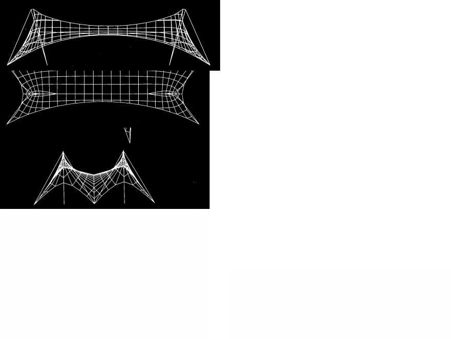
Anticlastic tensile structures are flexible membranes or cable nets of saddle-shaped curvature. The term membrane is used here to imply membranes and cable nets. Given the nature of flexible membranes, double curvature and prestress are essential for stability. This can be observed with simple string models. Two strings pulled in opposite directions stabilize a point at their intersection. If the strings are in non-parallel planes the stability will be three-dimensional. Similarly, if a series of strings cross in opposite directions they stabilize a series of points at their intersection. The cross points form a surface, stabilized by anticlastic curvature. The surface may be a membrane of fabric or other material or a cable net. Although anticlastic curvature provides stability, some elastic deformation is possible due to material elasticity. Thus, steel cable nets with high elastic modulus deform less than fabric membranes with lower stiffness.
In addition to curvature, prestress is also required to stabilize anticlastic membranes. This too can be observed on a string model. Applied load elongates one string in tension and shortens the other in compression. Without prestress, the compressed string will get slack and unstable; but prestressed strings absorb compressive stress by reduction of prestress. Since prestress renders both strings active to resist load, the resulting deflection is reduced to half compared to non-prestressed condition where only one string is active. This observation is also described under Prestress at the beginning of this chapter.
Flat membranes are unstable. This, too, can be observed on a string model. Two strings in a flat surface must deform into a polygon to resist load (a straight string would assume infinite forces). Therefore, flat membranes are unstable under load. Similarly, synclastic (dome-shape) membranes would deform excessively under gravity load and flutter in wind.
1Two strings crossing in non-parallel planes stabilize a point in space
2A series if strings (or a membrane) form a stable surface
3Without prestress, one string (or series of strings) would get slack under load, causing instability
4Strings in a flat surface deform excessively under load, causing instability
14-23 HORIZONTAL SYSTEMS Tensile Resistant
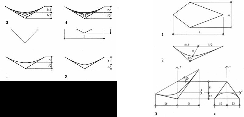
Minimal surface
As the name implies, a minimal surface covers any boundary with a minimum of surface area. The minimal surface is defined by three criteria:
•Minimum surface are between any boundary
•Equal and opposite curvature at any point
•Uniform stress throughout the surface
A minimal surface may be anticlastic or flat. A surface of flat or triangular boundaries is always flat. Flat membranes are unstable structures. Increased curvature increases stability. The minimal surface can be studied on soap film models; but they disappear quickly. The author studied quadrilateral plastic models that keep a minimal surface after drying. The models revealed:
f1/f2 = A/B
This is contrary to Hyperbolic Paraboloid shells. The surface of HP shells passes at midheight between low and high points regardless of boundary conditions.
1Minimal surface of square plan
2Minimal surface of rhomboid plan
3Hyperbolic Paraboloid of square plan
4Hyperbolic Paraboloid of rhomboid plan
Minimal surface equations
The minimal surface models also revealed equations that define the principle curvature of equilateral minimal surfaces (Schierle, 1977):
Y= f1(X/S1)(f1+f2)/f1 + X tan φ Y= f2 (Z/S2)(f1+f2)/f2
The equations are based on empirical studies of minimal surface models of plastic film, measured by means of a projected light grid with an accuracy of only 1.26% standard deviation. The findings were first published in the Journal for Optimization Theory and Application (Schierle, 1977)
Although the equations are for minimal surface of quadrilateral plans, they provide reasonable accuracy for other boundaries as well. This should be further studied.
1Plan view of quadrilateral minimal surface
2Length section of quadrilateral minimal surface
3Length section with Y-axis vertical
4Cross section
14-24 HORIZONTAL SYSTEMS Tensile Resistant
Saddle shapes
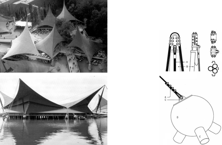
Structures symbolyzing mountens (top and sailing (bottom)
Expo ’64, Sector 7, Lausanne (1964)
Architect: Saugey / Schierle, Frei Otto, consultant Engineer: Froidveaux et Weber
Sector 7 of the Swiss Expo ’64 housed 26 restaurants, designed to connote mountains and sails as metaphor of Switzerland as vacation land. A village-like composition of quadrilateral membrane was nestled along and partly in lake Geneva to create a leisure setting. Each unit of 30/35m diagonal dimensions had three low points and one high point supported by steel mast. Colorful canvass membranes were stitched to cable nets in plastic tubes of 60/60cm meshes attached to edge cables. The high front was covered with a secondary membrane over a 3m tempered glass wall. Two prototypes of 15 and 23m high masts represented symbolic sails and mountain peaks, respectively.
1Top of tall mast
2Lake low point anchor
ACables
BTubular steel mast
CSteel anchor bracket
DConcrete sphere
ESteel piles
1
2
14-30 HORIZONTAL SYSTEMS Tensile Resistant
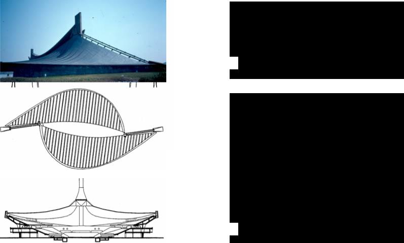
Olympic Pool Tokyo (1964)
Architect: Kenzo Tange
The 1964 Olympic pool structure consists of two anticlastic saddles, offset to form entries and supported by two cables draped over two concrete pylons. The anticlastic saddles are formed by flexible beams, designed to resist load in tension, but with some bending stiffness to facilitate a curvature suitable for natural ventilation through louvers attached to trusses that join the main cables.
Kagawa Gymnasium (1964)
Architect: Kenzo Tange
Built about the same time as the much larger Olympic arena in Tokyo, Tange’s design for the Kagawa gymnasium also features an anticlastic cable roof. The gymnasium of 4,707 m2 floor features two concave concrete walls that cantilever over 20 m from four giant concrete pillars to support a cable roof of 80m span in length direction. The gymnasium evokes the metaphor of a ship
14-31 HORIZONTAL SYSTEMS Tensile Resistant
1
2 |
3 |
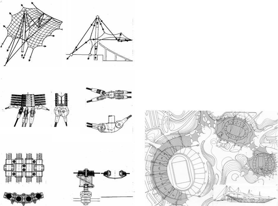
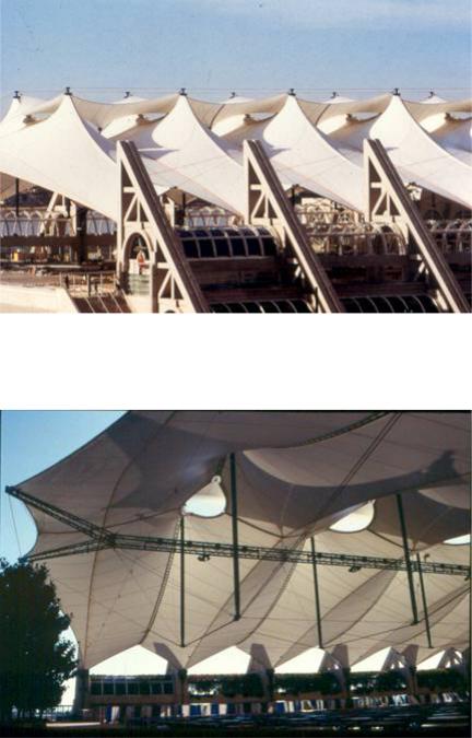
Olympic Roof, Munich (1972)
Architect: Guenther Behnisch, Frei Otto, consultant Engineer: Leonhard und Andrea / Schlaich
The metaphor for this projectwas a spider web hovering over the landscape to minimize the bulk, usually associated with sports facilities. The prefabricated cable nets consist of 75cm square meshes, that become rhomboids to assume anticlastic curvature. To facilitate this deformation net cables consist of two strands each, joint by concentric clamps. The cable roof covers stadium, arena, and swimming pool (clockwise from left to right in the site plan below). Acrylic panels, supported by neoprene cylinders attached to the cable net, provide natural lighting for optimal TV productions. The roof over enclosed spaces has thermal insulation (foam panels between two membranes). The thermal assembly provides a translucent enclosure for natural lighting. The stadium roof is supported by a ring cable, consisting of ten 100mm strands, suspended from steel masts by guy cables that also support flying buttresses that support cable net high points. The arena roof also has flying buttresses; the swimming pool roof is suspended from an external slanted mast. Unique hardware had to be custom designed and tested, a major factor for the high cost.
1Axon and section of typical stadium roof panel
2Cast steel joints of stadium edge cable
3Flying buttress support joint
4Hinged camp connecting adjacent cable nets
5Neoprene support and joint/gutter of 3/3m acrylic roof panels
4 |
5 |
|
|
||
|
|
14-32 HORIZONTAL SYSTEMS Tensile Resistant
Wave shapes
Recycling center project, Mil Valley, California (1971)
Architect: Neil Smith and G G Schierle Engineer: G G Schierle
This structure was designed to expand easily in response to needed growth, using a modular system. A base module of 25x80ft (7.6x24m) is supported by 22ft (6.7m) high masts. Two half end modules provide enclosure at both ends. Only one base module with both end enclosures is shown here. For sustainable energy efficiency the membrane was designed of translucent natural canvass allowing natural daylight. Edge, ridge, and valley cables where designed as bridge rope for flexibility in adjusting to the curvatures. Membrane prestress was introduced by turnbuckle adjustment at cable ends anchored to helix ground anchors. Variable prestress was required in order for the ridge cables to remain in vertical plains as required for repeatability of the modules. The prestress levels were determined by computer analysis. Mats were designed as standard steel pipes with pin joint attachment to the foundation. The pin joints avoided bending stress for optimal efficiency; moment resistant joints would introduce bending stress in the masts under any movement.
14-33 HORIZONTAL SYSTEMS Tensile Resistant
San Diego Convention Center (1987-89)
Architect: Arthur Erickson and a joint venture team Engineer/membrane designer : Horst Berger
The San Diego Convention Center features a linear plan of 1.7 million square feet (157,935 m2). Part of the top level is designed as outdoor exhibit space, covered with a wave-shape membrane roof. The membrane undulates between ridge and valley cables that are suspended from triangular concrete pylons. Openings at the membrane ridges provide natural ventilation. The openings are protected by secondary membranes hovering over them. Flying buttress masts supported by guy cables holding up ridge cables provide a column-free interior space. This complex support system makes the translucent fabric roof appear seemingly weightless hovering above the space, flooded in natural light. The guy cables are also suspended at both ends by triangular concrete pylons that contrast the lightweight roof with the solid conventional infrastructure. The Teflon-coated glass fiber membrane provides a fireproof enclosure, as required for permanent structures of this size.
14-34 HORIZONTAL SYSTEMS Tensile Resistant
Arch shapes
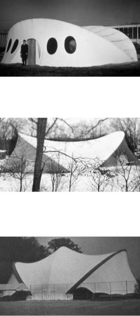
Portable classroom Detroit (1967)
Architect: G G Schierle
Engineer: Nick Forell
This portable classroom for Educational Facilities Laboratory, designed and built 1968 for ease of erection and transportation. The circular structure of 40 ft diameter consists of four circular aluminum arches supporting a two-layer fabric with pockets for 2 inch rigid thermal insulation. The four arches are hinge-joined to allow assembly on the ground. The structure is erected by rotating the arches in fan-like manner. Two arches are staked to the ground; the other two support the membrane and are stabilized by it. Elliptical doors and windows correspond to the respective fabric stress patterns. The PVC fabric has 600 pli tensile strength.
Theater pavilion, Armonk, NY (1968)
Architect: G G Schierle
Engineer: Nick Forell
This 80/120 ft theater pavilion was designed to be erected for occasional events, consists of two circular aluminum arches with hinge join to allow assembly on the ground. To be erected by rotating the arches about their hinge support. The fabric is attached to grade beams that are staked to the ground. The slanted aluminum arches are stabilized by the membrane, high-strength Hypalon fabric of 800 pli tensile strength. Elliptical door openings correspond to the respective fabric stress patterns. Within days after its first erection in winter 1968, the structure resisted unharmed snow load and wind gusts above the design load.
Tennis pavilion, Detroit (1968)
Architect: G G Schierle
This 60/120 ft tennis pavilion features side walls that are partly removable for natural ventilation. The remaining fabric has edge cables, tied to the ground by link cables. Three aluminum arches support the fabric and are stabilized by it. The arches are hinged at the base to allow erection on the ground. The translucent fabric provides diffused natural lighting. The third center arch provides the required height for unobstructed ball trajectories.
14-37 HORIZONTAL SYSTEMS Tensile Resistant
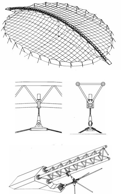
Skating rink, Munich (1983)
Architect: Kurt Ackermann Engineer: Sclaich Bergermann
This facility, initially designed as ice skating rink was recently converted into an inlineskating facility due to the increasing popularity of this new sport. The elliptical rink of 88x67m is covered by a cable net roof, suspended from a central arch and supported along the edges by a series if steel masts with guy cables. A prismatic trussed steel arch spans 104m between concrete abutments. The arch supports the cable net and is itself stabilized by it. The cable net is suspended to the arch by means of looping edge cables along the central spine. The space between the edge cables is designed as a skylight that exposes the arch from the inside and provides natural lighting in addition to a translucent roofing membrane. The cable net of double strands has 75x75cm meshes to which a lattice grid of wood slats is attached at the joints. A translucent PVC membrane is nailed to the lattice grid. This unusual combination of materials creates a unique interior spatial quality of quite elegance, contrasting the lightness of the translucent fabric membrane with the warms of the wood lattice grid.
14-38 HORIZONTAL SYSTEMS Tensile Resistant
Point shapes
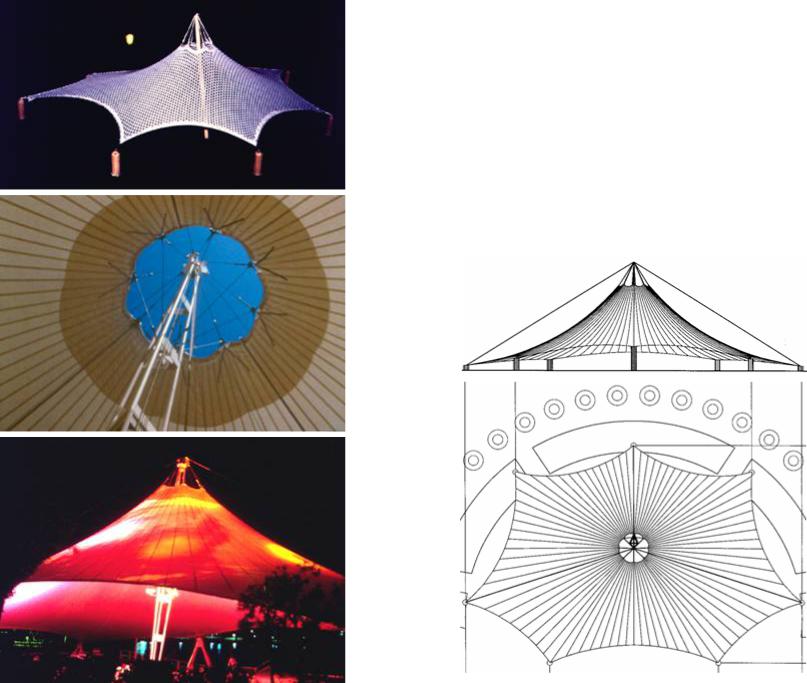
Sea World pavilion, Vallejo, California (1994)
Architect: G G Schierle Engineer: ASI
This conical pavilion is supported by a central steel mast and seven peripheral anchors of three steel pipes each. A loop cable and doubled fabric resists the fabric stress concentration on top. The loop cable is linked to the mast top by guy cables. Stay cables secure the mast top in case of fabric failure. The design process started with stretch fabric models exploring alternative designs. The final form and cutting patterns were defined by computer. Non-linear computer analysis also defined stress and deflection under various design loads. The conical fabric patterns where cut from fabric bands in reversed pairs to minimize waist.
14-39 HORIZONTAL SYSTEMS Tensile Resistant