

Architectural Structures
.pdfPrestress
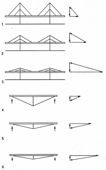
Tensile structures usually include flexible membranes and cables that effectively resist tensile forces but get slack under compression. Yet, under some load conditions, compressive forces may be induced in flexible tensile members. Prestress allows flexible members to absorb compressive stress without getting slack which would cause instability. Prestress also reduces deformation to half. These phenomena may be observed on a simple string.
Consider a vertical string fastened on top and bottom. If a load is applied at mid-height, the top link absorbs the entire load, and the lower link will get slack and unstable.
Now consider the same string prestressed (with turnbuckles for example). The same load applied at mid-height will be carried half by the top link (through increase of prestress) and half by the lower link (through decrease of prestress). Since both links are active, each will absorb only half the load, reducing the deformation to half and avoiding the lower link from getting slack and unstable. Since half the load is absorbed by each link, when the applied load reaches twice the prestress or more, the lower link will get slack, just as the string with no prestress. Given similar conditions in a structure, prestress should be at least half of the design load to prevent slack members and instability. Also, loss of prestress due to creep and temperature variation should be considered.
The correlation between prestress, load, and deformation, described above, is visualized in the stress/strain diagram below.
1String without prestress
2String with prestress
3Stress/strain diagram of both strings
AStress/strain line of un-prestressed string
BStress/strain line of prestressed string
CPoint where prestress is reduced to zero under load
DStress/strain line of string after loss of prestress
F |
Force |
f |
Stress |
P |
applied load |
PS |
Prestress |
|
Deformation |
14-2 HORIZONTAL SYSTEMS Tensile Resistant
Stayed Structures
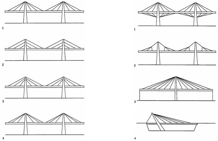
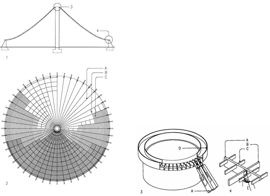
Stayed structures consist of beams or trusses that are intermittently supported by strands or rods (strands and rods have greater stiffness than wire ropes and hence reduce deflection). Although stays usually support structures, pulling from above, they may also push from below by means of compression struts. The latter is also referred to as cablepropped or just propped. Given the slope of stays, they generate not only a vertical uplift but also a horizontal reaction in the supported members and masts. In beams the horizontal reactions yield compression; in masts they introduce bending and overturn moments, unless stays on both sides balance the horizontal reactions.
The span/depth ratio of stayed and propped structures is an important design factor. A shallow depth results in great tension and compression in stays and beam respectively, a steep slope has the opposite effect. The relationship of cable slope and resulting forces is illustrated in the diagrams, showing various slopes and resulting forces for an assumed gravity load as vertical vector. Optimal span/depth ratios depend on both, architectural and structural factors. Architectural factors include appearance and spatial considerations. Structural factors include the impact on deflection, overall cost of stays, beams, masts, and compression struts. As a rule of thumb, the optimal slope for stays is about 30 degrees. Optimum span/depth ratio for propped systems is about 10 to 15.
1Steep stay slope causes small forces but high masts
2Stay slope of 25° to30° is usually optimal
3Shallow stay slope causes high forces but low masts
4Steep props cause small forces but great depth
5Span/depth ratio of about 10 to 15 is optimal
6Shallow props cause great forces but small depth
14-3 HORIZONTAL SYSTEMS Tensile Resistant
Configurations |
For light-weight roofs, with wind uplift greater than the roof dead weight, stays could by |
|||
Stayed structures may have radial or parallel strands, called radial and harp systems, |
added roof to resist wind uplift. Stays can also branch out like trees to reduce length. |
|||
respectively. Combinations of both systems are also possible. Harp systems have |
Single masts must be designed to resist overturning under unbalanced load. One-sided |
|||
constant stay forces; the force of radial systems varies with the stay slope. The tributary |
load |
causes unbalanced condition that require guy cables. The dead weight of an |
||
length between radial stays may be adjusted to keep forces constant, i.e., strands with |
inclined mast may help to balance loads. |
|||
shallow slope support small tributary lengths. |
1 |
Stay cables below the roof resist wind uplift |
||
1 |
Radial system (stay forces vary with slope) |
|||
2 |
Inverse tree stays reduce length but require more joints |
|||
2 |
Harp system (constant stay forces) |
3 |
Single tower with tie-downs at both beam ends to resist overturning |
|
3 |
Mixed system, combining radial and harp patterns |
4 |
One-sided support with guy cable are unbalanced and less efficient; |
|
4 |
System with variable distance between stay supports to equalize stay forces |
|
the inclined mast can help to balance the one-sided load |
|
14-4 HORIZONTAL SYSTEMS Tensile Resistant
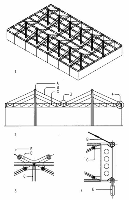
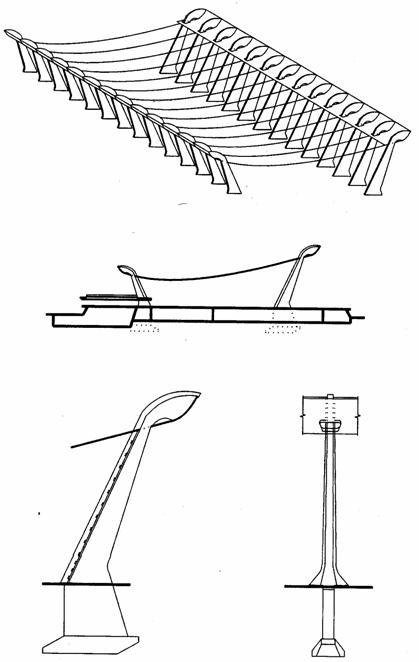
McCormick Place, Chicago (1987)
Architect: Skidmore, Owings and Merrill Engineer: Knight and Associates
The expansion of McCormick Place exhibit hall, located over existing railroad tracks, required a long-span roof to provide column-free exhibit space without interfering with the tracks. Several structure systems had been investigated before selecting a stayed roof. The roof is suspended from 12 concrete pylons, spaced 120x240ft, with 120ft overhangs on both long sides. The pylons project 60 feet above the roof. The clear interior height is 40 feet. Stay cables consist of 3.75in galvanized steel strands, coated with corrosion resistant PVC, arranged in parallel harp form at an angle of 25 degrees. The stays support steel trusses which support secondary trusses, both 15ft deep and exposed at the interior. The concrete pylons are shaped to incorporate mechanical ducts which bring conditioned air from a mezzanine below the main floor and exhaust it over the roof, without mechanical equipment exposed on the roof. The roof truss edges are tied to the podium of the main hall to provide stability for unbalanced load. The podium is supported by steel columns, spaced to accommodate the rail tracks. Combined with the deep trusses, the stays have enough redundancy that they can be removed and replaced without affecting the structure’s integrity. A glass band along the entire façade under the roof trusses and roof skylights, provide natural lighting.
1Isometric roof structure
2Cross-section of upper level with stayed roof
3Mid-span stay support detail
4Roof edge detail
AConcrete pylons, shaped to accommodate mechanical ducts
BStays, 3.75in galvanized steel strands, PVC coated
CTruss web bar
DStay connection bracket
ESteel tie secures roof to [odium
14-5 HORIZONTAL SYSTEMS Tensile Resistant
Suspended Structures
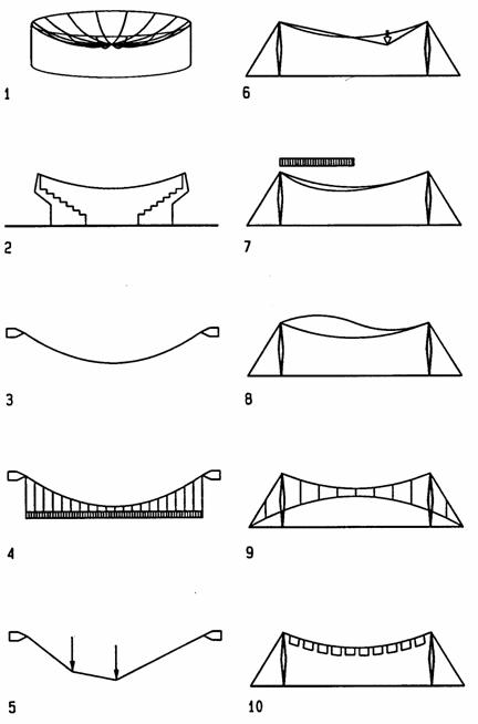
Suspended structures are used for long-span roofs. They are most effective if the curvature is compatible with spatial design objectives, and the horizontal thrust is resisted by a compression ring or by infrastructures, such as grandstands. Suspended cables effectively resist gravity load in tension, but are unstable under wind uplift and uneven loads. Under its own weight a cable assumes the funicular shape of a catenary (Latin for chain line). Under load uniformly distributed horizontally, the funicular will be parabolic; under point load the funicular is a polygon. Thus, without some means of stabilizing, cables assume different shapes for each load. Furthermore, under wind uplift suspended cables tend to flutter. Several means can be used to stabilize cables for variable loads and wind uplift. Among them are stabilizing cables, anticlastic (saddle-shaped) curvature, described later, and ballast weight. However, in seismic areas ballast weight would increase the mass and thus lateral loads.
1Suspended roof with compression ring to absorb lateral thrust
2Suspended roof with grandstands to resist lateral thrust
3Catenary funicular under cable self weight
4Parabolic funicular under horizontally distributed load
5Polygon funicular under point load
6Deformed roof under point load
7Deformed roof under uneven load (snow at one side, for example)
8Roof subject to wind uplift
9Roof with convex stabilizing cables to resist uplift and uneven loads
10Dead load to resist uplift and reduce deformation under uneven load
14-11 HORIZONTAL SYSTEMS Tensile Resistant
Dulles airport terminal, Washington, DC (1958-62)
Architect: Ero Saarinen Engineer: Ammann and Whitney
The Dulles international airport terminal near Washington, DC, has a cable roof supported by concrete pylons. The outward leaning pylons partly resist the cable thrust. Based on the dimensions of movable loading docks, designed by Saarinen, the pylons are spaced at 40 ft (12m) for a column-free concourse space of 150x600ft (46x183m), recently expanded, extruding the same structure. Given the slanted pylons, the suspension cables actually span 161 ft (49 m). Concrete edge beams span the pylons at heights that vary from 65ft (20m) along the entry to 40ft (12m) facing the runways. Suspended from the edge beams are 128 bridge strands of 1in (25mm) which support site-cast concrete roof panels. The concrete dead weight resists wind uplift and minimizes roof deformations under unbalanced roof loads. In Saarinen’s own words the Dulles roof is “a strong form between earth and sky that seems both to rise from the plain and hover over it.” It presents functional integrity and synergy of form and structure.
14-13 HORIZONTAL SYSTEMS Tensile Resistant
Recycling hall, Vienna (1981)
Architect: L. M. Lang
Engineer: Natterer and Diettrich
This recycling center features a tent-like wood structure of 560 feet (170m) diameter that soars to a height of 220 feet (67m) above ground, supported by a central concrete mast. The suspended wood roof consists of 48 radial laminated ribs that rise from outer concrete pylons with wood compression ring to the mast top. The ribs follow the funicular tension line to carry uniform roof load in pure tension, but asymmetrical loads may cause bending stress in the radial ribs that are designed as semi-rigid tension bands with some bending resistance capacity. Diagonal boards form the roofing membrane and add shear resistance to the assembly of ribs and ring beams. The cylindrical concrete support mast cantilevers from a central foundation. It was designed to resist asymmetrical erection loads and to contribute to lateral wind load resistance. The peripheral pylons are triangular concrete walls with metal brackets on top to secure the radial ribs.
1Cross section
2Roof plan
3Top of central support mast
4Typical roof assembly
ARadial laminated wood tension rib, 7.8x31-43 (20x80-110cm)
BLaminated wood ring beams, 5x15in (12x39cm)
CLaminated wood compression ring
DSteel tension ring
ESteel anchor bracket
14-16 HORIZONTAL SYSTEMS Tensile Resistant
Cable Truss
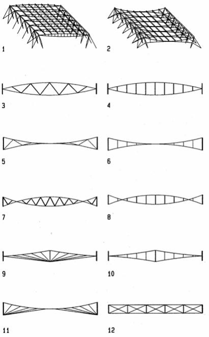
Cable trusses evolved from needs to stabilize suspension structures against wind uplift and unbalanced gravity loads, using a second set of cables with opposing curvature. The Swedish engineer Jawerth developed a cable truss with diagonal brace cables separating top supportand bottom stabilizing cables that resist wind uplift. This system was widely used in the 1960’s. Lev Zetlin and other US engineers designed cable trusses with various other configurations, including lintel shapes with compression struts separating bottom supportand top stabilizing cables. In 1969 the author and his students at UC Berkeley developed trusses with flat chord cables separated by compression struts and diagonal truss cables. Model tests, a full scale prototype, and extensive computer analysis demonstrated great stiffness of these trusses in one-way, two-way, and three-way layouts.
1Isometric of lintel trusses with bottom supportand top stabilizing cables separated by vertical compression struts
2Isometric of concave trusses with top supportingand bottom stabilizing cables separated by vertical tension struts
3Lintel truss with diagonal compression braces
4Lintel truss with vertical compression struts
5Concave truss with diagonal tension braces
6Concave truss with vertical tension struts
7Concave/lintel truss with diagonal compression braces
8Concave/lintel truss with vertical compression struts
9Concave gable truss with fan support and stabilizing cables and central compression strut
10Concave gable truss with tension struts and central compression strut
11Concave support cable and fan stabilizing cables
12Parallel chord truss, vertical compression struts and diagonal tension braces
14-17 HORIZONTAL SYSTEMS Tensile Resistant
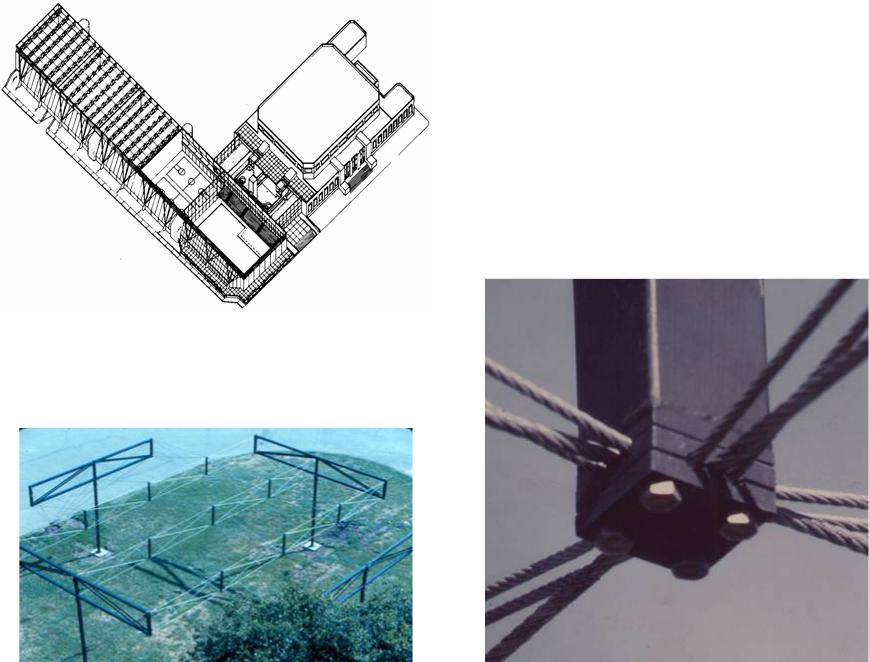
Sports center project, University of California, Berkeley (1975)
Architect: G G Schierle Engineer: T Y Lin
The Intramural sports center extension of the University of California Berkeley is a linear extrusion of four multipurpose gyms 120ft (37m) square and an Olympic swimming pool. An entrance hall facing the swimming pool links the new and existing facilities (at right in the drawing) via a linear circulation that also provides a visual link and overview of major spaces. Parallel chord cable trusses, spaced 20ft (6m), span the width of the facility. They are bilaterally braced by diagonal guy cables, designed to resist the horizontal thrust of the trusses and also provide lateral bracing for wind and seismic forces in both the length and width directions. The guy cable anchors line up with handball courts at the lower floor which absorb the horizontal force component of the guy cables. The guy cables express the lateral resisting system at the façade, much like buttresses on Gothic cathedrals.
Joint detail of prototype structure
Two-way prototype structure by students of the author at UC Berkeley (1975)
14-21 HORIZONTAL SYSTEMS Tensile Resistant
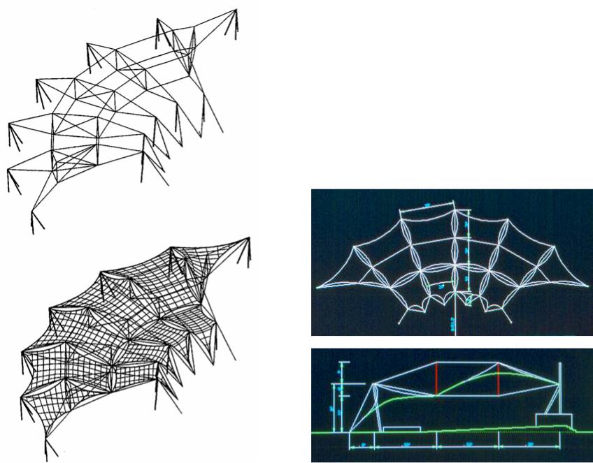
Watts Towers Crescent (1998)
Architect: G G Schierle with Joe Addo Engineer: ASI
A transparent membrane suspended from radial cable trusses is designed to provide sun shading for occasional performances at the Watts towers. The crescent-shaped roof follows the crescent-shaped seating below. The cable trusses minimize bulk for optimal view of the towers and facilitate fast erection and removal at annual events. The truss depth provides desired curvature for the anticlastic membrane panels. Two membranes provide shading for spectators and performers over the respective areas. The architectural design is shown below. The final computer drawings are shown at right.
14-22 HORIZONTAL SYSTEMS Tensile Resistant