

Architectural Structures
.pdfGarden show pavilion Hamburg (1963)
Architect: Frei Otto
This pavilion for the international Garden Show 1961 covers an area of 29/64m and has 5.5m high masts. The point shape roof was fabricated as flat fabric without patterns. The canvass stretched enough to assume the curvature between high and low points. The high points are supported by steel masts with laminated wood springs over octagonal steel ring to avoid stress peaks. Low points are anchored to the ground to resist wind uplift and act as drainage points with rain water collector basins. Membrane edge cables are anchored to the ground by guy cables.
Ice skating rink Villars, Switzerland (1959)
Architect: Frei Otto
The sunken skating area is surrounded by spectator seating and covered by a point shape canvass membrane roof of 32x64m. The roof membrane is hang from three suspension cables that span the length of the rink with steel masts at both ends. Metal dishes distribute the membrane stress at support points. Light fixtures are suspended from the same support points. Guy cables anchor membrane edge cables to the ground.
14-40 HORIZONTAL SYSTEMS Tensile Resistant
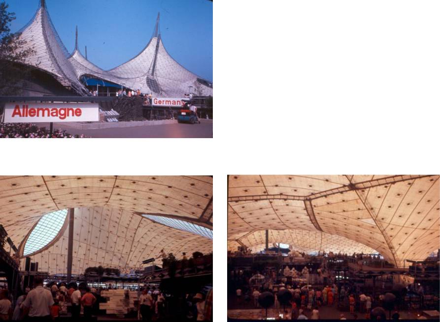
German Pavilion, Expo67, Montreal (1967)
Architect: Rolf Gutbrod and Frei Otto Engineer: Fritz Leonhard
The German Pavilion at Expo’67 in Montreal was the first price of design competition. Following the expo theme Terre des hommes, the objective was a man made landscape as free form roof of point shape membrane, suspended from eight high points on steel masts and low points for drainage. The membrane consisted of translucent fabric for natural lighting, suspended from a cable net of 60x60cm mesh size. Designed before computer programs became available, the structure was fabricated based on a 1:75 scale model that also served for structural testing. A full scale prototype was build to develop and test details and erection procedures. This prototype later housed the Institute of Lightweight Structures (IL). The structure was prefabricated in Germany and assembled on site. The cable net and masts where first erected. The fabric membrane was suspended from the net by means of turnbuckles and brackets, designed to allow adjustments between fabric and cable net.. The cable net was fabricated as a flat orthogonal net. During erection, the square meshes deformed into rhomboids to take the anticlastic curvature. High and low points where designed with eye loop cables to transfer membrane stress to mast tops. The eye lops featured skylights for natural lighting and to emphasize the support points.
14-41 HORIZONTAL SYSTEMS Tensile Resistant
Pneumatic Structures
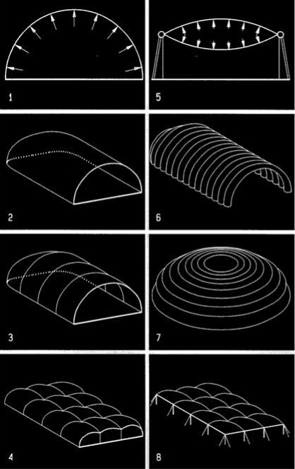
Pneumatic structures are flexible membranes that derive their stability from air pressure. They usually have synclastic curvature like domes, but anticlastic curvatures are possible as well. Two generic types of pneumatic structure are air supported (low pressure) and air inflated (high pressure) systems. The air pressure in inflated high pressure structures is 100 to 1000 times greater than in air supported low pressure structures.
Air supported structures typically have a single fabric layer enclosing a space in form of domes or similar shapes. The fabric is supported by inside air pressure. However, considering human comfort, air pressure can be only slightly higher than outside atmospheric pressure. The low air pressure makes air supported structures more vulnerable to flutter under wind load. Since the usable space is under air pressure, door openings must have air locks, usually in form of revolving doors to minimize loss of air pressure. Air supported structures require continuous air supply, usually with standby electric power generator to retain air pressure in case of power outage.
Air inflated structures are hermetically enclosed volumes that are inflated under high pressure much like a football to provide stability. They can have various tubular or cushion forms with high air pressure between two layers of fabric that provide usable space under normal air pressure. The air pressure ranges from 2 to 70 meters of water, yielding 2.8 to 100 pounds per square inch pressure, enough to resist gravity and lateral load. Without air pressure they would have no stability. Air inflated structures also require some continuous air supply to make up for pressure loss due to membrane leaks.
1Air supported dome or vault
2Air supported vault
3Air supported vault with support cables
4Air supported dome repetitions
5Air inflated cushion
6Air inflated tubular vault
7Air inflated tubular dome
8Air inflated cushion repetitions
14-42 HORIZONTAL SYSTEMS Tensile Resistant
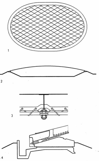
US Pavilion, Expo 70, Osaka (1970)
Architect: Davis, Brody, Chermayeff, Geismar, De Harak Engineer: David Geiger
The US Pavilion was the first large-scale pneumatic structure in 1970 with an elliptical plan of 466x272 feet (142x83 meters); yet rising only 20 feet (6 meters) from a peripheral earth berm, the structure had a very low profile. This shallow curvature was possible because the translucent roof membrane was laced to a grid of diagonal cables, spaced 20x20 feet (6x6 meter) that provided the primary support. The tension cables were supported by a concrete compression ring on top of the earth berm by means of adjustable anchor bolts. The compression ring formed a gutter to collect rain water along the periphery. Bending moments that could have been generated in the compression ring resulting of asymmetrical loads, were transferred to and resisted by the earth berm. The pavilion impressed not only by its great size but by its combination of understatement and technical innovation and refined sophistication.
1Elliptical roof plan
2Length section
3Laced membrane to cable attachment
4Concrete compression wing with gutter and adjustable cable anchors
14-43 HORIZONTAL SYSTEMS Tensile Resistant
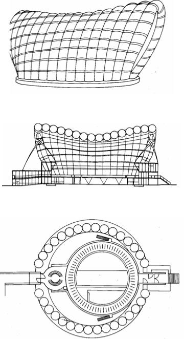
Fuji Pavilion, Expo 70, Osaka (1970)
Architect: Yutaka Murata Engineer: Mamoru Kawaguchi
The Fuji Pavilion housed an exhibit and light show of the Fuji corporation in a unique, organic form. Over a circular floor plan of 164 feet (50 meter) diameter, the pavilion featured a vaulted fabric structure composed of 16 pneumatic arched tubes. The tubes of 13 feet (4 meter) diameter were tied together by horizontal belts at 13 feet (4 meter) intervals. The tubes consisted of two vinyl fabric layers that were glued together for improved tear resistance. Given the circular floor plane, the arching tubes of equal length form cross sections that vary from semi-circular at the center to semi-elliptical at the entries on both opposite ends. To adjust the structure’s stiffness in response to various wind pressures, the tubes were connected by pipes to a multi-stage turbo blower, that provided 1,000 to 2,500 mm water pressure.
14-44 HORIZONTAL SYSTEMS Tensile Resistant
PART V |
15 |
VERTICAL SYSTEMS |
VERTICAL SYSTEMS |
|
General Background |
Vertical structures are presented in four categories, considering primary resistance to load: shear, bending, axial, and suspended (tensile). Although most structures combine several categories, one usually dominates. For example, axially stressed braced frames may also have moment resistant joints, yet the bracing provided most strength and stiffness.
Vertical structures have been a challenge since the famed tower of Babylon. Motivations to build tall structures include: a desire to reach toward heaven; to see the world from above; the prestige of being tallest, and high land costs. The tallest church tower in Ulm, Germany exemplifies the spiritual motivation. The Eiffel tower allows to see Paris from above. The towers of the Italian hill-town San Gimignano, and contemporary corporate office buildings express power and wealth; the latter are also motivated by high land cost. Traditional building materials like wood and masonry imposed height limitations overcome by new materials like steel and prestressed concrete. The Eiffel tower in Paris marks the beginning of tall steel towers. Prestressed concrete towers were pioneered 1955 by Fritz Leonhard with a television tower in Stuttgart.
15-1 VERTICAL STRUCTURES General Background
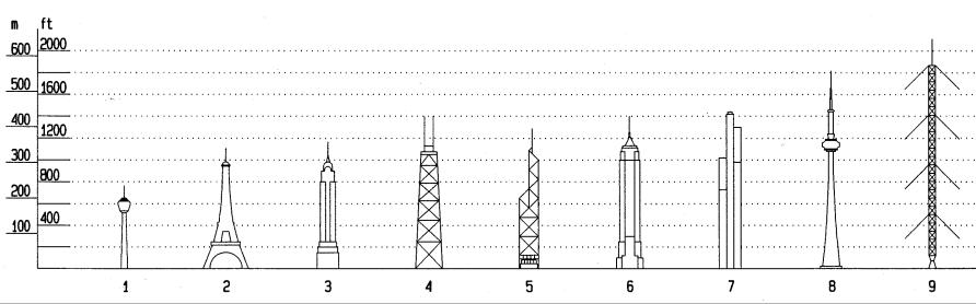
Tall Structures
1 |
SDR television tower Stuttgart |
1955 |
217 m |
712 feet |
2 |
Eiffel tower Paris |
1889 |
300 m |
984 feet |
3 |
Chrysler building New York, |
1930 |
319 m |
1047 feet |
4 |
John Hancock tower Chicago |
1968 |
344 m |
1127 feet |
5 |
Bank of China tower Hong Kong |
1988 |
369 m |
1211 feet |
6 |
Empire State building New York |
1933 |
381 m |
1250 feet |
7 |
Sears tower Chicago |
1974 |
443 m |
1453 feet |
8 |
CN tower Toronto |
1976 |
553 m |
1814 feet |
9 |
Transmission tower Warsaw |
1974 |
643 m |
2110 feet |
15-2 VERTICAL STRUCTURES General Background
Gravity load
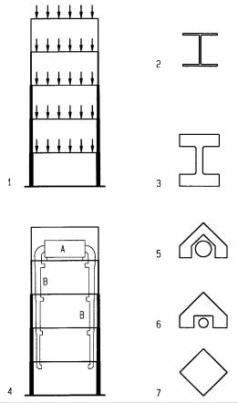
Gravity load is the combined live and dead load, acting vertically to generate compressive stress in supporting columns or walls. At every level they carry the combined loads from above. Since load accumulates from top down, members at the top carry the least, those at the bottom carry the most. Steel structures usually have the same nominal column size but of increasing unit weight, resulting in thin columns at top and bulky ones at ground level. For example W14 wide flange columns come in many weights from 43 to 730 plf (64 to 1,086 kg/m) with capacities of 272 to 4,644k (1,210 to 20,656 kN). It is also possible to use higher strength steel at lower floors. However, increase in steel strength does not yield higher stiffness since the modulus of elasticity of steel is constant regardless of strength. For concrete structures it is possible to increase concrete strength and stiffness, or to increase the cross sectional area. If a mechanical room is on the top floor it is possible to balance the decreasing need for duct sizes from top down, with need for increasing column sizes from top to bottom. Eero Saarinen designed the CBS tower New York with such a strategy but was only partly consistent since the lower floors are served from a mechanical room on the second floor.
1structure with increasing column size as load increases from top down
2Light-weight wide-flange column
3Heavy weight wide-flange column of equal nominal size as in 2 above
4Increasing column size dovetails with reducing duct size from top down
5Small column cross section and large duct size on top column
6Large column cross section and small duct size on lower floor column
7Large column on ground level where no duct space is needed
15-3 VERTICAL STRUCTURES General Background
Lateral load
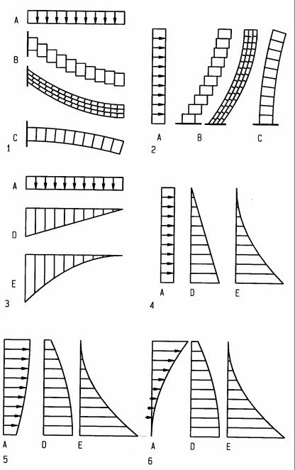
The effect of lateral load on tall structures is similar to gravity load on cantilevers, such as balconies. Tall structures act like cantilevers projecting from the ground. Lateral load generates shear and bending that may be presented in respective shear and bending diagrams as in a cantilever beam. Yet there are important differences, The shear and bending diagrams for buildings are usually global, for the entire system rather than for individual elements like beams. For example, global bending (overturn moment) causes axial tension and compression in columns, and local shear and bending in beams. Further, lateral wind and seismic loads are non-uniform. Wind force increases with height due to higher wind speed and reduced friction. Seismic forces increase with height in proportion to increasing acceleration (acceleration increases with height due to increased drift). However, shear increases from top to bottom since the structure at each floor must resist not only the force at that floor but the forces from all floors above as well. The non-uniform wind and seismic loads cause nonlinear shear distribution.
1Cantilever beam with shear and bending deformation
2Tall building with shear and bending deformation
3Shear and bending diagrams for uniform load on a cantilever beam
4Shear and bending diagrams for idealized uniform load on a building
5Vertical distribution of wind force, shear, and bending diagrams
6Vertical distribution of seismic force, shear, and bending diagrams
ALoad/force diagram
BShear deformation
CBending deformation
DShear diagram
EMoment diagram
15-4 VERTICAL STRUCTURES General Background
Lateral resistance
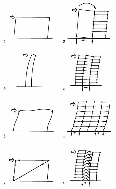
Lateral loads may be resisted by shear walls, cantilevers, moment frames, braced frames, or combinations thereof. The choice of a suitable system depends on structural and architectural objectives. Shear walls and braced frames are strong and stiff, cantilevers and moment frames are more ductile, to dissipate seismic energy. Shear walls are good for apartments or hotels that require party-walls between units. Moment frames offer better planning flexibility required for office buildings with changing tenant needs.
Shear walls resist lateral load primarily through in-plane shear. They may be of reinforced concrete or masonry, or, for low-rise, of wood studs with plywood or particle board sheathing. Short shear walls tend to overturn and must be stabilized by dead load or tie-downs.
Cantilevers are slender elements that resist load primarily in bending. Pole houses are cantilevers; but more commonly, cantilevers are of reinforced concrete or masonry, anchored to foundations, wide enough to resist overturn. Overturn cause compression on one side and tension on the other. Compression acts in addition to gravity, tension may be partly offset by gravity compression. In tall cantilevers, tension due to lateral load may be greater than gravity compression, resulting in net tension.
Moment frames consistent of posts and beams connected by moment resistant joints. They may be of steel or reinforced concrete. To resist seismic load, concrete should have ductile reinforcement that yields before brittle concrete failure. Ductile design results in greater concrete members with less reinforcing steel.
Braced frames may have diagonal-, A-, X-, or V-braces. The best bracing scheme depends on structural and architectural considerations. K-bracing tend to buckle columns and must not be used. X-bracing allows no doors and requires more joints for greater cost; but X-bracing can be of tension rods to eliminate buckling. A- and V-braces are shorter than single diagonals and result in reduced buckling. (however, beams must be designed for the full span since bracing may adversely effect the beam load). Braced frames are usually of steel but may be of reinforced concrete or wood (for low-rise).
1Long shear wall resists in-plane load in shear primarily
2Shear wall supports adjacent bays (slender walls tend to overturn)
3Cantilever resists lateral load primarily in bending
4Cantilever supporting adjacent bays
5Moment frame requires moment resisting beam-column joints to resist lateral load by beam-column interaction
6Moment frames at both ends supports intermittent bays
7Braced frame with diagonal bracing
8braced center core supports adjacent bays
15-5 VERTICAL STRUCTURES General Background