

Architectural Structures
.pdfOutput display
Output includes member force, stress, deformation, joint displacement and rotation, as well as support reactions, all as numeric tables and color graphs. Clicking any member or joint provides detailed information. Force and stress include axial, bending, shear, as well as combined axial and bending stress. Based on the output, members may be resized in proportion to stress or strain. Animation allows to visualize deformation correlated with force or stress patterns.
Bending stress
Axial stress
Shear stress
Deflection with colored stress (also available in animation mode)
10-30 DESIGN METHODS Conceptual Design
Belt truss effect
CAD-analysis provides efficient means to compare framing systems. For convenience the following example was done with constant W18 beams and W14 columns, 30’ beam spans, and 12. story heights. The results, comparing the effect of belt and top trusses on a moment frame and a braced frame are very reveling:
20-story moment frame |
|
|
Gravity load |
w = 3 klf |
|
Wind load |
P = 10 k / level |
|
Frame: |
Drift |
|
Frame only |
15.1” |
|
Top truss |
14.9” |
|
Belt truss |
14.2” |
|
Top and belt truss |
14.0” |
|
20-story braced frame |
|
|
Gravity load |
w = 3 klf |
|
Wind load |
P = 10 k / level |
|
Frame |
Drift |
|
Frame only |
17.6” |
|
Top truss |
11.4” |
|
Belt truss |
11.1” |
|
Top and belt truss |
8.6” |
|
Note:
Belt and top trusses are much more effective to reduce drift at the braced frame than at the moment frame. The combined belt and top trusses reduce drift:
•7 % at moment frame
•49 % at braced frame
Interpreting the results clarifies the stark difference and fosters intuitive understanding of different deformation modes of moment and braced frames.
10-31 DESIGN METHODS Conceptual Design
PART IV
HORIZONTAL SYSTEMS
Part III presents structure systems, divided into two categories: horizontal, and vertical/lateral. Horizontal systems include floorand roof framing systems that support gravity deadand live load and transfer it to vertical supports, such as walls and columns. As the name implies, vertical/lateral systems include walls, columns and various other framing systems that resist gravity load as well as lateral windand seismic load.
In the interest of a structured presentation, both, horizontal and vertical/lateral systems are further classified by type of resistance controlling the design. This also helps to structure the creative design process. Though many actual systems may include several modes of resistance, the controlling resistance is assumed for the classification. For example, cable stayed systems usually include bending elements like beams, in addition to cables or other tension members. However, at least at the conceptual level, their designed is controlled more by tension members than by bending. Therefore they are classified as tensile structures. Horizontal systems are presented in four chapters for structures controlled by bending, axial, form and tensile resistance. Vertical/lateral systems are presented in three chapters for structures controlled by shear-, bending-, and axial resistance.
11
HORIZONTAL SYSTEMS
Bending Resistant
Bending resistant systems include joist, beam, girder, as well as Vierendeel frame and girder, folded plate and cylindrical shell. They carry gravity load primarily in bending to a support structure. Shear is typically concurrent with bending, yet bending usually controls the design. Though bending resistant elements and systems are very common, they tend to be less efficient than other systems, because bending varies from maximum compression to maximum tension on opposite faces, with zero stress at the neutral axis. Hence only half the cross-section is actually used to full capacity. Yet, this disadvantage is often compensated by the fact that most bending members are simple extrusions, but trusses are assembled from many parts with costly connections. Like any structure system, bending elements are cost effective within a certain span range, usually up to a maximum of 120ft (40m). For longer spans the extra cost of more complex systems is justified by greater efficiency.
PART IV HORIZONTAL SYSTEMS Bending Resistant
Bending Concepts
Some concepts are important for an the intuitive understanding of bending members and their efficient design. They include the effects of span and overhang, presented in this section. Other concepts, such as optimization and the Gerber beam, are included in the following section.
Effect of span
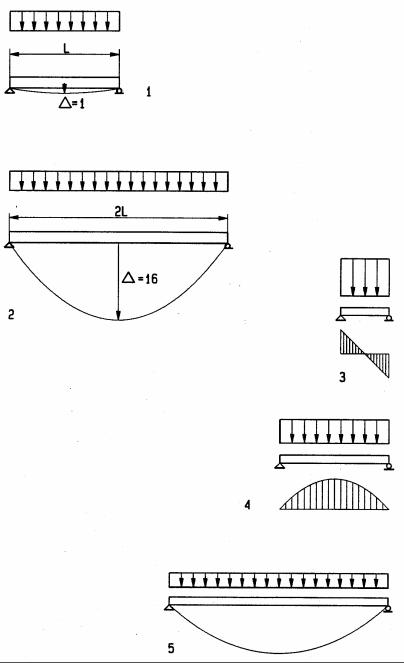
The effect of the span L for bending members may be demonstrated in the formulas for deflection, bending moment and shear for the example of a simple beam under uniform load.
∆= (5/384) wL4/ (EI) M= wL2/8
V= wL/2 where
∆= Maximum deflection E= Elastic modulus
I = Moment of Inertia L= Length of span
M= maximum bending moment V= maximum shear force
w= Uniform load per unit length
The formulas demonstrates, deflection increases with the 4th power of span, the bending moment increases with the second power, and shear increases linearly. Although this example is for a simple beam, the same principle applies to other bending members as well. For a beam of constant cross-section, if the span is doubled deflection increases 16 times, the bending four times, but shear would only double. Thus, for long bending members deflection usually governs; for medium span bending governs, yet for very short ones, shear governs
1Beam with deflection ∆ = 1
2Beam of double span with deflection ∆ = 16
3Short beam: shear governs
4Medium-span beam: bending governs
5Long-span beam: deflection governs
11-1 HORIZONTAL SYSTEMS Bending Resistant
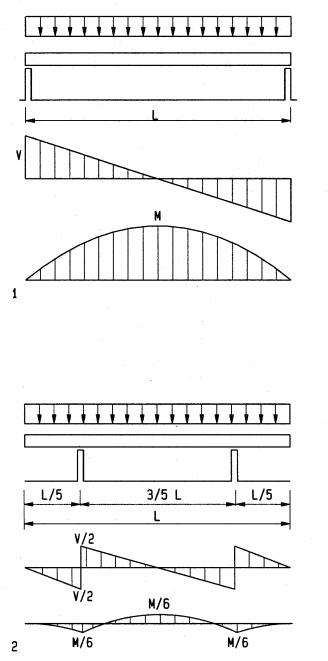
Effect of overhang
Bending moments can be greatly reduced, using the effect of overhangs. This can be describe on the example of a beam but applies also to other bending members of horizontal, span subject to gravity load as well. For a beam subject to uniform load with two overhangs, a ratio of overhangs to mid-span of 1:2.8 (or about 1/3) is optimal, with equal positive and negative bending moments. This implies an efficient use of material because if the beam has a constant size – which is most common – the beam is used to full capacity on both, overhang and span. Compared to the same beam with supports at both ends, the bending moment in a beam with two overhangs is about one sixth ! To a lesser degree, a single overhang has a similar effect. Thus, taking advantage of overhangs in a design may result in great savings and economy of resources.
1Simple beam with end supports and uniform load
2Cantilevers of about 1/3 the span equalize positive and negative bending
moments and reduces them to about one sixth, compared to a beam of equal length and load with but with simple end support
11-2 HORIZONTAL SYSTEMS Bending Resistant
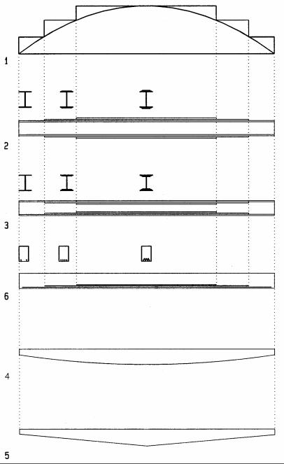
Beam optimization
Optimizing long-span girders can save scares resources. The following are a few conceptual options to optimize girders. Optimization for a real project requires careful evaluation of alternate options, considering interdisciplinary aspects along with purely structural ones.
1Moment diagram, stepped to reflect required resistance along girder
2Steel girder with plates welded on top of flanges for increased resistance
3Steel girder with plates welded below flanges for increased resistance
4Reinforced concrete girder with reinforcing bars staggered as required
5Girder of parabolic shape, following the bending moment distribution
1 Girder of tapered shape, approximating bending moment distribution
11-3 HORIZONTAL SYSTEMS Bending Resistant
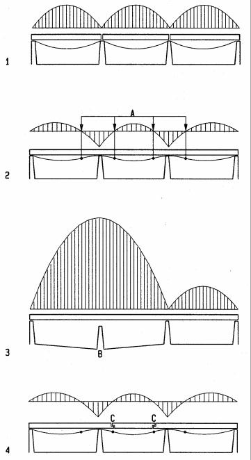
Gerber beam
The Gerber beam is named after its inventor, Gerber, a German engineering professor at Munich. The Gerber beam has hinges at inflection points to reduce bending moments, takes advantage of continuity, and allows settlements without secondary stresses. The Gerber beam was developed in response to failures, caused by unequal foundation settlements in 19th century railroad bridges.
1Simple beams over three spans
2Reduced bending moment in continuous beam
3Failure of continuous beam due to unequal foundation settlement, causing the span to double and the moment to increase four times
4Gerber beam with hinges at inflection points minimizes bending moments and avoids failure due to unequal settlement
11-4 HORIZONTAL SYSTEMS Bending Resistant
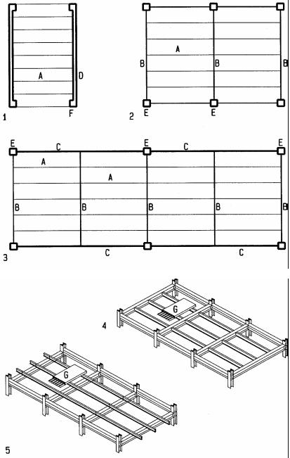
Joist, Beam, Girder
Joists, beams, and girders can be arranged in three different configurations: joists supported by columns or walls1; joists supported by beams that are supported by columns2; and joists supported by beams, that are supported by girders, that are supported by columns3. The relationship between joist, beam, and girder can be either flush or layered framing. Flush framing, with top of joists, beams, and girders flush with each other, requires less structural depth but may require additional depth for mechanical systems. Layered framing allows the integration of mechanical systems. With main ducts running between beams and secondary ducts between joists. Further, flush framing for steel requires more complex joining, with joists welded or bolted into the side of beams to support gravity load. Layered framing with joists on top of beams with simple connection to prevent displacement only
2Single layer framing: joists supported directly by walls
3Double layer framing: joists supported by beams and beams by columns
4Triple layer framing: joists supported by beams, beams by girders, and girders by columns
5Flush framing: top of joists and beams line up May require additional depth for mechanical ducts
6Layered framing: joists rest on top of beams Simpler and less costly framing
May have main ducts between beams, secondary ducts between joists A Joists
B Beam C Girders D Wall
E Column F Pilaster
GConcrete slab on corrugated steel deck
11-5 HORIZONTAL SYSTEMS Bending Resistant
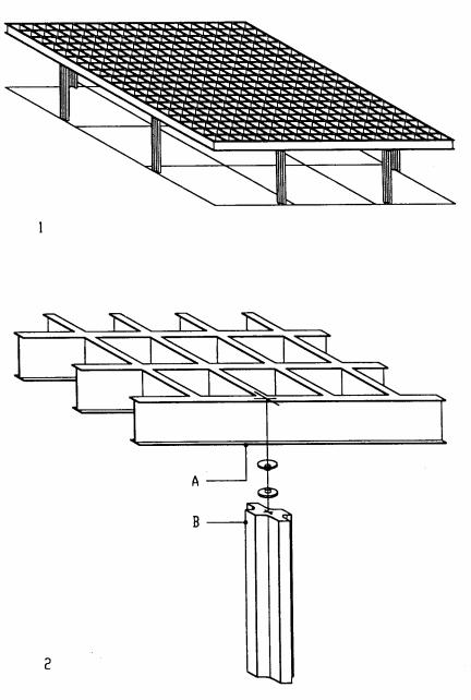
National Gallery, Berlin (1968)
Architect: Mies van der Rohe
The National Gallery was initially commissioned in 1962 for Berlin’s twentieth century art collection. In 1965 it was merged with the National-galerie and renamed accordingly. A semi-subterranean podium structure of granite-paved concrete is the base for the main structure, a steel space-frame of 64.8m (212ft) square has a clear interior height 8.4m (28ft). At the roof edge eight cross-shaped steel columns with pin joint at the roof cantilever from the podium for lateral resistance. Based on a planning module of 1.2m, the unique space-frame consists of two-way steel shapes, 1.8m deep, spaced 3.6m on center in both direction. The shallow span/depth ratio oh 33 required the roof to have a camper to cancel deformation under gravity load. The entire roof was assembled on ground from factory pre-welded units and hydraulically lifted in place on a single day.
1Steel roof framing concept
2Steel roof framing detail
ASteel edge beam
BCross-shaped steel column
11-7 HORIZONTAL SYSTEMS Bending Resistant
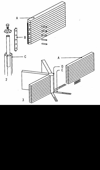
School in Gurtweil, Germany (1972)
Architect: H. Schaudt
Engineer: Ingenieurbüro für Holzbau
A grid of equilateral triangles is the base of this honeycomb of ten hexagonal classrooms. The side length of each regular hexagon is 5.4 m (18 ft). The composition of classrooms defines a free-form hall with entry from a central court. The sloping site provides space for a partial ground floor for auxiliary spaces below the classroom level.
Laminated beams spanning three ways presented a challenge to minimize the number of beam intersections. The continuous beams need moment connections. To this end, the main roof and floor structures have identical configurations but different support conditions. Six columns support each hexagonal classroom at the vertices. The classroom floors have an additional column at the center of each hexagon to support the cross point of three girders that span the six hexagon vertices. Those columns do not interfere with the auxiliary spaces below classrooms. Three beams span between the girders to form four triangular panels. Floor joists rest on the beams and support a particle board sub-floor with acoustical and thermal insulation. To provide uninterrupted classrooms, the roof structure has no column support within each hexagon. The columnfree spaces required beams with moment connections. The roof deck consists of planks with tongue-and-groove. Diagonal steel rods, 24 mm (1 in) φ, with turnbuckles, brace some peripheral columns to resist lateral wind load.
1Floor structure (roof is similar but without column at hexagon centers)
2Column supporting center of floor hexagon
3Moment resistant joint of roof beam at hexagon center without column
ALaminated girder, 12x60 cm (5x24")
BSteel insert bar with dowels ties beams to column
CHexagonal laminated column, φ21 cm (8")
DHigh-strength concrete core resists compression at top of roof beam
ESteel strap, 10x80 mm (3/8x3"), resists tension at bottom of roof beam
ETension straps, 10x80mm, at bottom of beams
11-8 HORIZONTAL SYSTEMS Bending Resistant