

Architectural Structures
.pdfJoist support
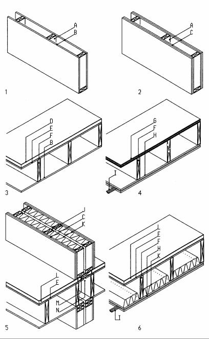
Beams may support joists two ways, flush support and top support. Flush support (beam and joist with flush top)
•Requires metal joist hangers
•Is more labor intensive to install
•Provides narrow joist support
•Has shorter joists
•Conceals beam within depth of joists
•Prevents ducts and pipes to pass between joists over beam
•Reduces story height
Top support (joist rest on top of beam)
•Needs no connecting hardware
•Is less labor intensive an simple to install
•Provides wider support and better safety
•Requires slightly longer joists to overlap over the beam
•Exposes the beam below the ceiling
•Allows ducts and pipes to pass between joist over the beam
•Increases story height
1Flush support with joist hanger
2Flush support with joist hanger on steel beam with wood ledger
3Flush support with double flange joist hanger
4Hybrid support on wood ledger on steel beam
5Top support overlapped on wood beam
6Top support overlapped on steel beam with wood ledger
20-22 MATERIAL Wood
Fire and sound rating
Some aspects of fire and sound rating have important structural implications. Fire ratings define the time a structure retains its integrity while exposed to fire. Codes require fire rating for buildings based on floor area, occupancy and type of construction. Fire rated walls may also separate large buildings into smaller areas considered separate buildings. For light-weight wood structures a layer of 5/8 in Type X gypsum board on each side of the wall provides one hour fire rating. A second layer on each side provides two-hour fire rating. Fire rating of floors requires, in addition to gypsum board on the ceiling, lightweight concrete or thick floor plywood.
Sound rating provides privacy in party walls and floors separating adjacent apartments, condominiums, or offices. The Impact Insulation Class (IIC) for floors and Sound Transmission Class (STC) for both floors and walls define sound ratings. IIC and STC ratings of 50 are the typical minimum standard for party floors and walls. However, quality construction requires IIC and STC ratings of at least 60. To offset electric outlets on both sides of a party wall by one stud space is essential for the integrity of sound rated walls; so is the elimination of plumbing pipes in party walls. A continuous sound gap in plywood floors prevents floor sound to telegraph from unit to unit. Yet the sound gap breaks the structural integrity of the floor diaphragm. A plate, bridging the gap and nailed to both sides of the plywood gap can re-establish structural continuity of the plywood diaphragm.
1One hour fire rated wall
2Two-hour fire rated wall
3One hour fire rated floor
4Two-hour fire rated floor
5Sound rated wall of about 60 STC
6Sound rated floor of about 60 IIC and 60 STC
AWall studs.
BGypsum board, 5/8" type X (fire rated)
CGypsum board, 2 layers 5/8" type X each side
DCellular concrete, 1.5"
EPlywood sub-floor, minimum 5/8"
FJoists
GPlywood sub floor, 1"
HGypsum boards, 2 layers 5/8" type X (type x is fire rated)
IResilient furring channels, spaced 24"
JDouble studs with minimum 1" sound gap
KGlass fiber insulation
LCellular concrete, 1.5" with carpet and pad floor
MPlate to transfer shear over sound gap in plywood
NSound gap in plywood to prevent sound transmission
20-25 MATERIAL Wood
23
Concrete
Material
Concrete is a versatile material that can be molded into many forms. It was first known in ancient Rome. Quarrying limestone for mortar, the Romans discovered that burning the limestone mixed with silica and alumina yields a cement stronger and more adhesive than ordinary lime mortar. The new material also could be used for underwater construction. Mixing the cement with sand and other materials, the Roman's invented the first concrete and used it widely in their construction, often filled between masonry.
The technology of concrete construction was lost with the fall of the Roman empire. Only toward the end of the eighteenth century did British inventors experiment to develop concrete again. In 1825, Joseph Aspdin patented Portland cement which he named after Portland limestone of similar color. The material was soon in wide use and the name Portland cement is still common today. It consists of lime, silica, and alumina, burned to clinkers in a furnace at about 3000º F (1650º C), and then crushed to a fine powder.
Concrete, consisting of cement, sand, and gravel mixed with water, is strong in compression, but very weak in tension and shear. Thus, concrete by itself is limited to applications subject to compressive stress only. This limit was soon recognized and by 1850 several inventors experimented with adding reinforcing steel to concrete. In 1867 the French gardener, Joseph Monier, obtained a patent for flower pots made of reinforced concrete. He went on to build water tanks and even bridges of reinforced concrete. Monier is credited to invent reinforced concrete..
As any material, concrete has advantages and disadvantages. Concrete ingredients are widely available and rather inexpensive. Concrete combines high compressive strength with good corrosion and abrasion resistance. It is incombustible and can be molded in many forms and shapes. Concrete's main disadvantage is its weakness in resisting tension and shear. Steel reinforcing needed to absorb tensile stress can be expensive. Concrete has no form by itself and requires formwork that also adds much to its cost. The heavy weight of concrete yields high seismic forces but is good to resist wind uplift. Concrete is inherently brittle with little capacity to dissipate seismic energy. However, concrete frames with ductile reinforcing can dissipate seismic energy. The inherent fire resistance of concrete is an obvious advantage in some applications.
Today, concrete serves many applications usually with reinforcing. In buildings, concrete is used for items like footings and retaining walls, paving, walls, floors, and roofs. Concrete is also used for moment resistant frames, arches, folded plates and shells. Apart from buildings, many civil engineering structures such as dams, bridges, highways, tunnels, and power plants are of concrete.
23-1 MATERIAL Concrete
Concrete properties
Normal concrete has compressive strengths of 2 to 6 ksi (14 to 41 MPa)and high strength concrete up to 19 ksi (131 MPa). Low-strength concrete is used for foundations. Concrete strength is determined by the water-cement ratio (usually 0.6) and the cement- sand-gravel ratio (usually 1-2-3). Specified compressive strength of concrete ƒ‘c, usually reached after 28 days, defines concrete strength. By the strength method (ultimate strength method) a structure is designed to 85% of the specified compressive strength ƒ‘c, with factored loads as safety factor. By the working stress method, a structure is designed to allowable stress, i.e., a fraction of the specified compressive strength ƒ‘c.
Allowable concrete stress for working stress method |
|
|
|
|
|
Compressive bending stress |
|
0.45 |
ƒ‘c |
||
Bearing stress (full area): |
|
0.25 |
ƒ‘c |
||
Bearing stress (1/3 area): |
beam |
0.375 |
ƒ‘c |
||
Shear stress without reinforcing: |
1.1 |
ƒ‘ |
c |
1/2 |
|
|
joist |
1.2 |
ƒ‘ |
1/2 |
|
|
c |
||||
|
footing and slab |
2.0 |
ƒ‘ |
1/2 |
|
|
c |
||||
Shear stress, with reinforcing: |
|
5 |
ƒ‘ |
1/2 |
|
|
|
||||
Elastic modulus (w = concrete density In pcf): |
|
w1.5 33 |
ƒ‘c1/2 |
||
|
|
|
|
c |
|
Temperature increase causes expansion of concrete defined by the thermal coefficient α=5.5x10⁻⁶ in/in/°F (3.1x10⁻⁶ m/m/°C). Hence, concrete slabs need temperature reinforcing to prevent cracks due to uneven expansion. Concrete also has creep deformation over time, mostly during the first year. Concrete shrinks about 1.3% due to loss of moisture, notably during curing. The temperature reinforcing helps to reduce shrinkage cracks as well. Density of concrete is determined by the type of aggregate. Light-weight concrete weighs about 100 pcf (1602 kg/m3). Normal concrete 145 pcf (2323 kg/m3) without reinforcing and 150 pcf (2403 kg/m3) with reinforcing.
Concrete has good fire resistance if reinforcing steel is covered sufficiently.
A 8 in (20 cm) wall has 4 hours and a 4 in (10 cm) wall 2 hours fire resistance.
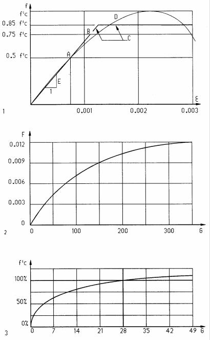
1Stress-strain curves for concrete
2Concrete creep (deflection with time)
3Concrete strength increase with time as percentage of 28-day strength
APoint defining line of E-module on curve
BElastic limit of idealized line for working stress method
CIdealized line for strength method
DActual stress-strain curve
EElastic modulus, defined as the slope from 0 to 0.5 ƒ‘c ε Unit strain, in/in (m/m)
FUnit creep strain, in/in (m/m)
GDays after pouring concrete
23-2 MATERIAL Concrete
Cement comes in bags of 1 ft3 (.028 m3), classified by ASTM-C150 as:
Type I Normal cement (for most general concrete) Type II Moderate resistance to sulfate attack Type III High early strength
Type IV Low heat (minimizes heat in mass concrete, like dams) Type V High resistance to sulfate attack
Types IA, IIA, IIIA correspond to I, II, III, but include air-entraining additives for improved workability and frost resistance.
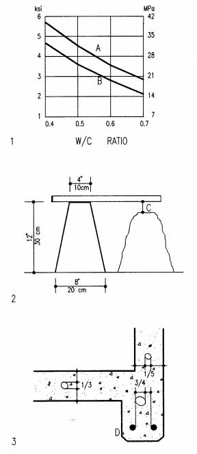
Water must be clean, free of organic material, alkali, oil, and sulfate. The water-cement ratio defines the strength and workability of concrete. Low water content yields high strength, but is difficult to work. Typical water ratios are 0.4 to 0.6, verified by a slump test. For this test, a metal cone is filled with concrete and tamped. Lifting the cone slumps the concrete to under 3 in (7 cm) for foundations and walls, and 4 in (10 cm) for columns and beams.
Aggregate should be clean and free of organic material. Fine aggregate (sand) is less than 1/4 in (6 mm). Coarse aggregate (gravel or crushed rock) is used in normal concrete. Lightweight concrete has aggregate of shale, slate, or slag. Perlite and Vermiculite are aggregates for insulating concrete.
Admixtures are substances added to concrete to modify its properties:
•Air entrained agents improve workability and frost resistance
•Accelerators reduce the curing time and increase early strength
•Retarders slow the curing and allow more time to work the concrete
•Plasticizers improve the workability of concrete
•Colors and pigments add colors to concrete
Curing of concrete is a process of hydration until it reaches its full strength. Although this process may take several months, the design strength is reached after 28 days. During the curing process the concrete should remain moist. Premature drying results in reduced strength. Exposed concrete surfaces should be repeatedly sprayed with water or covered with a protective membrane during curing. This is most important in hot or windy climates. The curing process accelerates in hot temperatures and slows down in cold temperatures. Concrete shrinks about 2 % during curing. This may cause cracks. Synthetic fibers of 1/8 to 3/4 in (3 to 20 mm) are increasingly added to improve tensile strength and reduce cracking of concrete.
1Concrete compressive strength defined by water-cement ratio
2Slump test: sheet metal cone and slumped concrete, C = slump
3Maximum aggregate sizes: 1/3 of slab, 1/5 of wall, 3/4 of bar spacing
ACompressive strength of normal concrete
BCompressive strength of air entrained concrete
CSlump is the amount the wet concrete settles
23-3 MATERIAL Concrete
Beam Reinforcement
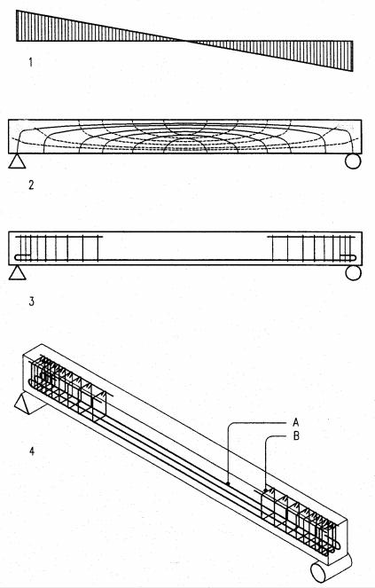
Concrete beams require reinforcement for bending and shear in correlation with the respective stress patterns. This is illustrated for a simply supported beam under uniform load and for other beams on the next page.
Bending reinforcement is placed where the bending moment causes tensile stress. A simply supported beam under uniform gravity load deforms downward to generate compression on top and tension at the bottom. Thus, bending reinforcement is placed at the bottom. Beams with negative bending require tensile reinforcement on top. This is the case in beams with moment resistant supports, cantilever beams, and beams continuing over three or more supports. Some beams may require additional bars at mid-span or over supports to resist increased bending moment. Beams of limited depth also require compressive reinforcement to make up for insufficient concrete. Some reinforcement bars have hooks at both ends to anchor them to the concrete if the bond length between steel and concrete is insufficient. Deformed bars usually don’t need hooks, given sufficient bond length. Temperature reinforcement continuous over the full length to resist stress caused by temperature variation and shrinkage during curing.
Shear reinforcement is placed where the shear stress exceeds the shear strength of concrete which is very small compared to compressive strength. Beams under uniform gravity load have maximum shear at supports which decreases to zero at mid-span. Thus, shear reinforcement in form of stirrups is closely space near the supports and spacing increases toward mid-span. Stirrups are usually vertical for convenience, though combined horizontal and vertical shear stresses generate diagonal tension which may cause diagonal cracks near the supports. Small longitudinal bars on top of a beam tie the stirrups together.
1Shear diagram: maximum shear at supports and zero at mid-span
2Isostatic or principal stress lines: diagonal tension, dotted, near support
3Side view of beam with reinforcement
4Three-D view of beam with reinforcement
ABottom steel bars resist tensile stress
BStirrups resist shear stress which, for uniform load, is maximum at the supports and zero at mid-span
23-6 MATERIAL Concrete
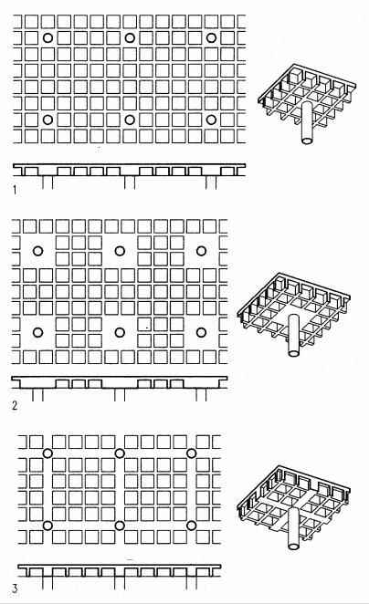
Waffle slab
Waffle slabs are two-way systems for medium spans where flat slabs or plates would be too deep and too heavy. They reduce dead weight by two-way ribs to eliminate excess weight between the ribs. The tensile steel for positive bending is placed at the bottom of ribs and the rib top and slab resist compressive stress. Since negative bending reverses the stress, waffle slabs are not efficient as cantilever with negative bending. Given the relative narrow spacing of ribs, minimum slab depth is determined not by its span/depth ratio, but by rebar size plus concrete cover. Waffle slabs need either solid panels on top of columns to resist shear stress or require intermediate beams. Waffle slabs are formed placing re-usable prefabricated pans of plastic or steel over a grid of wood boards.
Waffle slabs may be designed by the previously described Direct Design Method like a flat slab on columns but with reduced dead load due to ribs.
Waffle slab dimensions:
Span/depth ratio L/d = 16-32 (d = waffle depth) Maximum span 60’ ( m); 70’ ( m) when prestressed Slab depth 2.5” to 4.5” (6 to 11 cm)
Total depth 10” to 24” (25 to 60 cm) Rib width 5” to 8” (13 to 20 cm) Waffle size 2’ to 5’(60 to 150 cm)
1Waffle slab with a single solid panel over columns
2Waffle slab with four solid panels over columns
3Waffle slab supported by beams
23-12 MATERIAL Concrete
Prestressed concrete
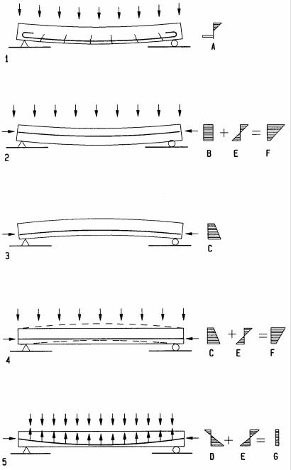
The effect of prestress on concrete is to minimize cracks, reduce depth and dead weight, or increase the span. Analogy with a non-prestressed beam clarifies this effect. In a simply supported non-prestressed beam the bottom rebars elongate in tension and concrete cracks due to tensile weakness. In prestressed concrete tendons (high-strength steel strands) replace rebars. The tendons are pulled against concrete to compress it before service load is applied. Service load increases the tension in tendons and reduces the initial concrete compression. Avoiding tensile stress in concrete avoids cracks that may cause corrosion in rebars due to moisture. Further, prestress tendons can take the form of bending moments that balances the service load to minimize deflection. This, combined with higher strength concrete of about 6000 psi (40 MPa), allows for longer span or reduced depth in beams.
Pre-tensioning and post-tensioning are two methods to prestress concrete. They are based on patents by Doehring (1886) and Jackson (1888); yet both were unsuccessful due to insufficient stress that dissipated by creep. Doehring stressed wires before casting the concrete, and Jackson used turnbuckles to stress iron rods after the concrete had cured. Subsequent experiments by others led to the first successful empirical work by Wettstein in 1921 and the first theoretical study by French engineer Eugene Freyssinet during 1920, followed by his practical development. In 1961 the US engineer T Y Lin pioneered prestress tendons that follow the bending diagram to balance bending due to load. Lin’s method controls deflections for any desired load, usually dead load and about half the live load. By his method, before live load is applied a beam (or slab) bows upward. Under full load, they deflect and under partial live load they remain flat. Diagram 5 illustrates this for a simply supported beam.
1Simply supported beam without prestress, cracked at tensile zone
2Prestress beam with concentric tendon deflects under service load
3Prestress beam with eccentric tendon pushes up without service load
4Same beam as 3 above with service load balanced at max. mid-span moment but not elsewhere since tendon eccentricity is constant
5Prestress beam with parabolic tendon to balance bending moment
ABending stress: top concrete compression and bottom steel tension
BPrestress uniform due to concentric tendon
CPrestress with greater compression near tendon at bottom
DPrestress for eccentric tendon: bottom compression and top tension (tension where tendon is outside beam’s inner third (Kern). Simply supported beam of zero end moments has concentric tendon at ends
EService load stress: top compression and bottom tension
FCombined stress from prestress and service load
GCombined stress with uniform distribution due to balanced moments
23-17 MATERIAL Concrete
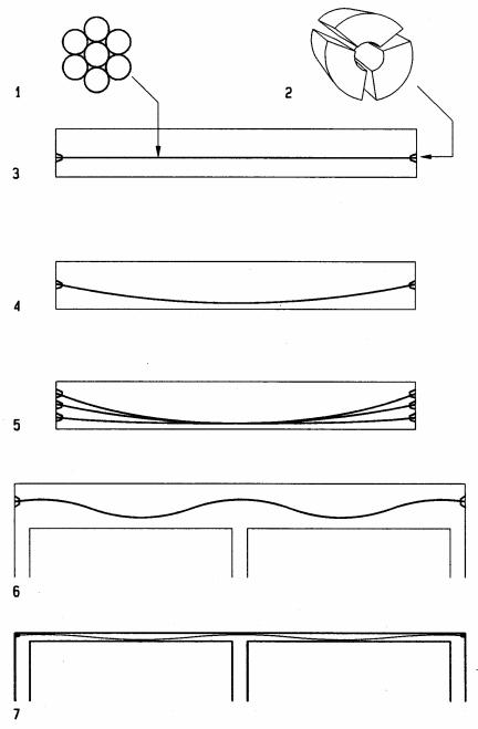
Tendons are high strength steel strands used in prestressed concrete. They have a breaking strength of 270 ksi (1860 MPa) and are composed of 7 wires, six of them laid helically around a central wire. Tendons come in sizes of 0.5 and 0.6 in (13 and 15 mm) diameter. Both sizes are used in post-tensioned concrete but only small tendons are used in pre-tensioned concrete which requires no bond length. The great strength of tendons allows initial stress levels high enough to make up for loss of stress due to creep, most notably during initial curing.
Post-tensioning begins by placing of metal or plastic tubes that house the prestress tendons prior to the pouring of concrete. Some tendons come enclosed in the tubes, but most are inserted after concrete has cured. Tubes prevent tendons to bond with the concrete to allow free movement for subsequent prestress operation. Once concrete has reached sufficient strength, the tendons are prestressed using hydraulic jacks that press against concrete to transfer prestress into it. Short members have tension applied at one end only but long members may require tension at both ends to overcome friction. Several devices are available to anchor the ends of post-tensioned tendons into concrete. One such device is a conical wedge that holds tendons by mechanical friction between the tendon and a rough surface of the device. Post-tensioning is usually done at the building site. It allows tendons to take any form desired to balance bending moments induced by service load.
1Tendon cross section.
2Conical tendon lock rests against steel sleeve (not shown) inserted into concrete and squeezes the tendon and hold it by friction
3Beam with straight eccentric tendon below neutral axis
4Parabolic tendon emulate bending moment to reduce deflection
5Multiple parabolic tendons with offset anchors
6Continuous beam with tendons emulating bending moment distribution
7Continuous slab with tendons emulating bending moment distribution
23-18 MATERIAL Concrete
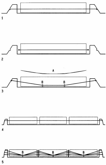
Pre-tensioning stresses tendons between abutments in a concrete precasting plant. Once concrete has sufficient strength (with the help of steam in about 24 hours) tendons are cut off at the abutments to transfer prestress into the concrete. After cut off, tendons are anchored by friction with the concrete at both ends. Since abutments are difficult to secure at construction sites, pre-tensioning is usually done in a precast plant. Similar pieces may be laid in a row and cast together requiring only two abutments per row. Pretensioning is simplest with straight tendons, but some approximate curves that emulate bending moments are possible. They require temporary tie-downs to be cut off along with tendons after curing is complete.
Pre-tensioned members must be carefully handled during transportation to avoid damage or breakage. Since the reinforcement is designed for a given load direction, any reversed load may result in overstress and possible breakage. To avoid this they must be placed on the truck in the same position as in their final installation. Also, to avoid breakage of corners, it is advisable to provide corners with chamfers.
1Beam with tendons anchored to abutments
2Beam with tendons cut off to transfer prestress into concrete after it has reached sufficient strength
3Beam with tendon tie-down to approximate bending moment curves
4Row of pre-tensioned members with tendon anchors at ends only
For members like walls and columns with possible bending in any direction, tendons may be placed at the center
5Row of pre-tensioned beams with tendon tie-down to approximate bending moments of service loads
AClose approximation of parabolic bending moment by tendon shape
BTemporary tendon tie-downs to approximate bending moments are cut off after tendons are cut from abutments
23-19 MATERIAL Concrete