

Architectural Structures
.pdfHillside construction
To avoid expensive earthquake settlement repair ……
………. adapt building to site rather than adapting site to building
9-25 DESIGN METHODS Lateral Force Design
A A B  B
B
6" MAX
12" MAX
6" MAX
6" MAX
C C |
DD |
E
E
|
PLWD. |
GYP/FIBER BD. |
|
3.5 |
1.5 |
F F |
GG 1.0 |
1.0 |
H H
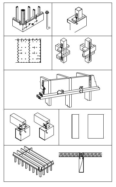
Critical wood-frame items
A |
Item |
Requirements |
|
Shear wall anchor bolts |
Resist wall slippage |
|
|
B |
Hold-down |
Resist shear wall overturning |
|
C |
Shear wall nailing |
Attach panels to framing |
|
D |
Wall-to-wall hold-down |
Resist shear wall overturning |
|
E |
Framing anchor clips |
Transfer shear from floor to floor |
F |
Beam connection |
Resist beam slippage |
G |
Shear wall width/height ratio |
Minimum 1 : 3.5 for stability |
|
Wood panels |
1:3.5 (Los Angeles, 1:2) |
|
Gypsum board |
1:2 |
H |
Joist blocking |
Transfers shear at panel edges |
9-26 DESIGN METHODS Lateral Force Design
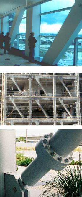
Bracing
Eccentric bracing allows to adjust stiffness, providing:
•greater stiffness than moment frame
•less stiffness than braced frame
•Short link beam provides stiffness
•Long link beam provides ductility Note:
Link beam is the distance between brace support and column Typical link beam length is about 20 percent of beam length
Visco-elastic bracing provides:
•Stiffness for normal load
•Ductility for big seismic load
9-27 DESIGN METHODS Lateral Force Design
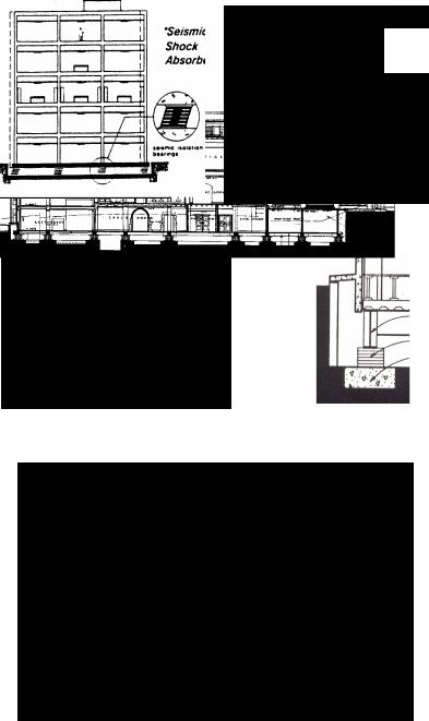
Base Isolator
Left: Conventional structure
•Large total and inter-story drift
•Accelerations increase with height
•Potential permanent deformations
•Potential equipment damage
Right: Base isolators:
•Reduce floor accelerations and drift
•Reduce damage to structure and equipment
•Are not good for high-rise structures
Left: Base isolator make-up
•Top and bottom steel plate
•Rubber sheets
•Steel sheets
•Central lead core
Right: Separate building from ground to allow drift
UCLA Kerckhoff Hall base isolator upgrade
Drawings, courtesy Widom Wein Cohen Architects, Santa Monica
9-28 DESIGN METHODS Lateral Force Design
10
Conceptual Design
Introduction
Conceptual design usually starts with approximate sizing principle elements of a structure and possible alternatives, followed by thorough analysis during design development. Approximate methods are essential to quickly develop alternate designs. They are also useful to verify final designs and computer analysis. If based on good assumptions, approximate methods can provide results of remarkable accuracy, usually within ten percent of precise results. The following conceptual design examples introduce approximate methods, sometimes referred to as back-of-the-envelop design. They are not meant to replace accurate design but as precursor of accurate design and analysis.
System Selection
Structural design starts with the selection of a system and material; often informed by similar past projects, even if not appropriate. For example, light wood structures are common for residential building where hurricanes cause frequent destruction, though heavy concrete or masonry would resist wind load much better. A rational method is proposed with the objective to select more appropriate systems. However, since design criteria may be conflicting in some cases, selection is both art and science, yet the following criteria make the selection process more objective
•Capacity limit
•Code requirements
•Cost
•Load
•Location
•Resources
•Technology
•Synergy
Capacity limit is based on limits of systems and materials. For example, beams are economical for a given span range. To exceed that range would yield a bad ratio of dead load to live load. A beam’s cross section increases with span, resulting in heavier dead load. Eventually, the beam’s dead load exceeds its capacity and it would break. Approaching that limit, the beam gets increasingly uneconomical because its dead weight leaves little reserve capacity to carry live load. The span limit can be extended by effective cross section shape. For example, steel beam cross sections are optimized in response to bending and shear stress, to allow greater spans.
Trusses have longer span capacity than beams, due to reduced self weight. They replace the bulk of beams by top and bottom chords to resist global moments, and vertical and diagonal web bars to transfer shear between compression and tension chords. Compared to beams, the greater depth of trusses provides a greater lever arm between compression and tension bars to resist global moments. Similarly, suspension cables use the sag between support and mid-span as moment resisting lever arm. Since cables have higher breaking strength and resist tension only, without buckling, they are optimal for long spans; but the high cost of end fittings makes them expensive solutions for short spans. These examples show, most systems have upper and lower span limits.
Code requirements define structures by type of construction regarding materials and systems; ranging form type I to type V for least and most restrictive, respectively, of the Uniform Building Code (UBC) for example. Each type of construction has requirements for fire resistance, maximum allowable floor area, building height, and occupancy group. Codes also have detailed requirements regarding seismic design; notable structures are categorized by ductility to absorb seismic energy and related height limits. Some code requirements are related to other criteria described in the respective section.
10-1 DESIGN METHODS Conceptual Design
Cost is often an overriding criteria in the selection of structures. in fact, cost is often defined by some of the other selection criteria. However, costs also depends on market conditions and seasonable changes. The availability of material and products, as well as economic conditions and labor strikes may greatly effect the cost of structures. For example, a labor strike in the steel industry may shift the advantage to a concrete structure, or the shortage of lumber, may give a cost advantage to light gauge steel instead of light wood framing. Sometimes, several systems are evaluated, or schematic designs are developed for them, in order to select the most cost effective alternative.
Load imposed on a structure is a major factor in selecting a system. For example, roofs in areas without snow must be designed only for a nominal load, yet roof load in mountain areas may be up to 20 times greater than the nominal load. Structures in earthquake prone areas should be lightweight and ductile, since seismic forces are basically governed by Newton’s law, force equals mass times acceleration (f=ma). In contrast, structures subject to wind load should be heavy and stiff to resist wind uplift and minimize drift. Structures in areas of daily temperature variations should be designed for thermal load as well, unless the structure is protected behind a thermal insulation skin and subjected to constant indoor temperature only.
Location may effects structure selection by the type of soil, topography, ground water level, natural hazards, such as fire, frost, or flood. Local soil conditions effect the foundation and possibly the entire structure. Soft soil may require pile foundations; a mat foundation may be chosen to balance the floating effect of high ground water. Locations with winter frost require deep foundations to prevent damage due to soil expansion in frost (usually a depth of about one meter). Hillside locations may require caisson foundations to prevent sliding, but foundations are more common on flat sites. Locations with fire hazards require non-combustible material. Raising the structure off the ground may be the answer to flooding.
Resources have a strong impact on the selection of structure materials. Availability of material was a deciding factor regarding the choice of material throughout history. The Viking build wood structures, a logical response to the vast forests of Scandinavia, yet stone temples of Egypt and Greece reflect the availability of stone and scarcity of wood. More recently, high-rise structures in the United States are usually steel structures, but the scarcity of steel in some other countries makes concrete structures more common.
Technology available at a area also effects the selection of structures. For example, light wood structures, known as platform framing, is most common for low rise residential structures in the United States, where it is widely available and very well known; but in Europe where this technology is less known, it is more expensive than more common masonry structures. Similarly, in some areas concrete technology is more familiar and available than steel technology. Concrete tends to be more common in areas of low labor cost, because concrete form-wok is labor intensive. On the other hand, prefab concrete technology is less dependent on low labor cost and more effected by market
conditions, namely continuity of demand to justify the high investments associated with prefab concrete technology.
Synergy, defined as a system that is greater than the sum of its parts is a powerful concept to enrich architecture, regarding both pragmatic as well as philosophic objectives. Pragmatic example are numerous: Wall system are appropriate for hotel and apartment projects which require spatial and sound separation; but moment frames provide better space planning flexibility as needed for office buildings. However, the core of office buildings, usually housing elevators, stairs, bathrooms, and mechanical ducts, without the need for planning flexibility, often consists of shear walls ore braced frames, effective to reduce drift under lateral loads. Long-span systems provide column-free space required for unobstructed views in auditoriums and other assembly halls; but lower cost short span systems are used for warehouses and similar facilities where columns are usually acceptable.
On a more detailed level, to incorporate mechanical systems within a long-span roof or floor structure, a Vierendeel girder may be selected instead of a truss, since the rectangular panels of a Vierendeel better facilitate ducts to pass through than triangular truss panels. A suspended cable roof may be selected for a sports arena if bleachers can be used to effectively resist the roof’s lateral thrust which is very substantial and may require costly foundations otherwise. Synergy is also a powerful concept regarding more philosophical objectives, as demonstrated throughout history, from early post and beam structures; Roman arches, domes and vaults; Gothic cathedrals; to contemporary suspension bridges or roofs. Columns can provide architectural expression as in post and beam systems, or define and organize circulation, as in a Gothic cathedral. The funicular surface of arches, domes and vaults can define a unique and spiritual space. The buttresses to resist their lateral thrust provides the unique vocabulary of Gothic cathedrals. Large retaining walls may use buttressing for rhythmic relieve, as in the great wall of Assisi, or lean backward to express increased stability as the wall of the Dalai Lama palace in Tibet.
10-2 DESIGN METHODS Conceptual Design
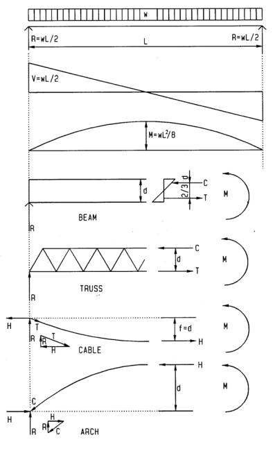
Global moment and shear
Global moments help to analyze not only a beam but also truss, cable or arch. They all resist global moments by a couple F times lever arm d:
M = F d; hence F = M / d
The force F is expressed as T (tension) and C (compression) for beam or truss, and H (horizontal reaction) for suspension cable or arch, forces are always defined by the global moment and lever arm of resisting couple. For uniform load and simple support, the maximum moment M and maximum shear V are computed as:
M = w L2 / 8
V = w L / 2
w = uniform gravity load L = span
For other load or support conditions use appropriate formulas Beam
Beams resist the global moment by a force couple, with lever arm of 2/3 the beam depth d; resisted by top compression C and bottom tension T.
Truss
Trusses resist the global moment by a force couple and truss depth d as lever arm; with compression C in top chord and tension T in bottom chord. Global shear is resisted by vertical and / or diagonal web bars. Maximum moment at mid-span causes maximum chord forces. Maximum support shear causes maximum web bar forces.
Cable
Suspension cables resist the global moment by horizontal reaction with sag f as lever arm. The horizontal reaction H, vertical reaction R, and maximum cable tension T form an equilibrium vector triangle; hence the maximum cable tension is:
T = (H2 + R2)1/2
Arch
Arches resist the global moment like a cable, but in compression instead of tension:
C = (H2+R2)1/2
However, unlike cables, arches don’t adjust their form for changing loads; hence, they assume bending under non-uniform load as product of funicular force and lever arm between funicular line and arch form (bending stress is substituted by conservative axial stress for approximate schematic design).
10-3 DESIGN METHODS Conceptual Design
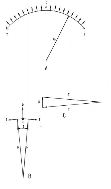
Radial pressure
Referring to diagram A, pressure per unit length acting in radial direction on a circular ring yields a ring tension, defined as:
T = R p
T = ring tension R = radius of ring
p = uniform radial pressure per unit length
Units must be compatible, i.e., if p is force per foot, R must be in feet, if p is force per meter, R must be in meters. Pressure p acting reversed toward the ring center would reverse the ring force from tension to compression.
Proof
Referring to ring segment B:
T acts perpendicular to ring radius R
p acts perpendicular to ring segment of unit length Referring to ring segment B and vector triangle C: p and T in C represent equilibrium at o in B
T / p = R / 1 (due to similar triangles), hence T = R p
10-4 DESIGN METHODS Conceptual Design
Examples
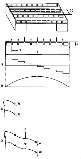
Vierendeel Girder
Assume
Steel girders spaced 20’ |
L = 100’ |
|
Allowable stress (60% of Fy = 46 ksi tubing) |
Fa = 27.6 ksi |
|
DL= |
18 psf |
|
LL = |
12 psf (20 psf reduced to 60% for tributary area > 600 sq. ft.) |
|
Σ = |
30 psf |
|
Uniform girder load |
|
|
w = 30 psf x 20’ / 1000 |
w = 0.6 klf |
|
Joint load |
|
|
P= w e = 0.6 x 10’ |
P = 6 k |
|
Vertical Reaction |
|
|
R= w L / 2 = 0.6 x 100’ / 2 |
R = 30 k |
|
END BAY CHORD |
|
|
Chord shear |
|
|
Vc= (R – P/2) / 2 = (30 – 6/2) / 2 |
Vc = 13.5 k |
|
chord bending |
|
|
Mc = Vc e/2 = 13.5 x 10’x12” / 2 |
Mc = 810 k” |
|
Moment of Inertia required |
|
|
I= Mc c/ Fa = 810x5”/27.6 ksi |
I = 147 in4 |
|
Use ST 10x10x5/16 |
I = 183 > 147, ok |
|
WEB BAR (2nd web resists bending of 2 adjacent chords) |
|
|
2nd bay chord shear |
|
|
Vc= (R-1.5 P)/2 = (30–1.5x6)/2 |
Vc = 10.5 k |
|
2nd bay chord bending |
|
|
Mc = Vc e/2 = 10.5x10’x12”/2 |
Mc = 630 k” |
|
Web bending |
|
|
Mw = Mc end bay + Mc 2nd bay = 810 + 630 |
Mw = 1,440 k” |
|
Moment of Inertia required |
|
|
I = Mw c/Fa = 1,440x5/27.6 |
I = 261 in4 |
|
Use ST 10x10x1/2 web bar |
I =271 > 261, ok |
|
MID-SPAN CHORD (small chord bending ignored) |
|
|
Mid-span global bending |
|
|
M= w L2/8= 0.6x1002/8 |
M = 750 k’ |
|
Mid-span chord force |
|
|
P= M/d= 750/6 |
P= 125 k |
|
Use ST 10 x 10 x5/16 |
297 > 125, ok |
|
10-5 |
DESIGN METHODS Conceptual Design |
|
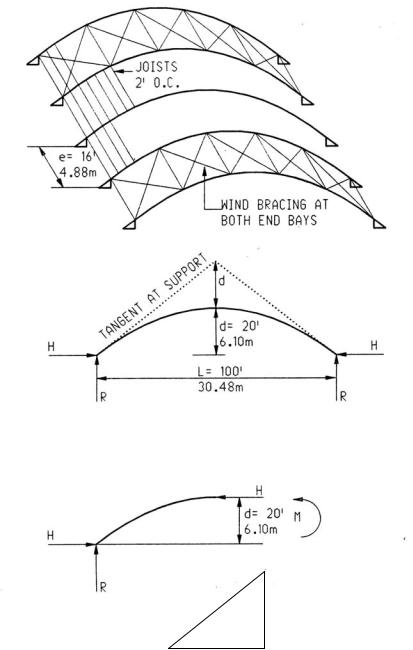
Wood Arch
Assume
Glue-lam, spaced 16’, 3-hinged for transport and to avoid settlement stress. dimensions: ¾” lams; 31/8”, 51/8”, 6¾”, 8¾” and10 ¾” wide).
Allowable buckling stress (from case studies)
LL = 12 psf (reduced to 60% of 20 psf for tributary area > 600 sq. ft.) DL = 18 psf (estimate)
Σ =
Uniform load
w = 30 psf x 16’ / 1000 = Global moment
M = w L2 / 8 = 0.48 x 1002 / 8 =
Horizontal reaction
H = M / d = 600 / 20 =
Vertical reaction
R = w L /2 = 0.48 x 100’ / 2 = Arch compression (max.)
C = (H2 + R2)1/2 = (30 2 + 24 2 )1/2 Cross section area required
A = C / Fc’ = 38 / 0.2 ksi
Glue-lam depth (try 5 1/8” wide glue-lam)
t = A / width = 190 / 5.125 = 37; use 50 lams of ¾” Check slenderness ratio
L / t = 100’ x 12” / 37.5” =
Note:
Arch slenderness of L/t = 32 is ok (the 5 1/8” arch width is braced against buckling by the roof diaphragm).
Wind bracing at end bays may consist of diagonal steel rods in combination with compression struts. The lateral thrust of arches may be resisted by concrete piers that may be tied together by grade beams to resist the lateral arch thrust.
Final design must consider non-uniform load (snow on half the arch) resulting in combined axial and bending stress; the bending moment being axial force times lever arm between funicular pressure line and arch center. The funicular line may be found graphically.
Graphic method
•Draw a vector of the computed vertical reaction
•Draw equilibrium vectors parallel to arch support tangent
•Equilibrium vectors give arch force and horizontal reaction
10-6 DESIGN METHODS Conceptual Design