

Architectural Structures
.pdfFlexure Formula
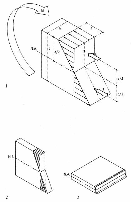
The flexure formula gives the internal bending stress caused by an external moment on a beam or other bending member of homogeneous material. It is derived here for a rectangular beam but is valid for any shape.
1Unloaded beam with hatched square
2Beam subject to bending with hatched square deformed
3Stress diagram of deformed beam subject to bending
Referring to the diagram, a beam subject to positive bending assumes a concave curvature (circular under pure bending). As illustrated by the hatched square, the top shortens and the bottom elongates, causing compressive stress on the top and tensile stress on the bottom. Assuming stress varies linearly with strain, stress distribution over the beam depth is proportional to strain deformation. Thus stress varies linearly over the depth of the beam and is zero at the neutral axis (NA). The bending stress fy at any distance y from the neutral axis is found, considering similar triangles, namely fy relates to y as f relates to c; f is the maximum bending stress at top or bottom and c the distance from the Neutral Axis, namely fy / y = f / c. Solving for fy yields
fy = y f / c
To satisfy equilibrium, the beam requires an internal resisting moment that is equal and opposite to the external bending moment. The internal resisting moment is the sum of all partial forces F rotating around the neutral axis with a lever arm of length y to balance the external moment. Each partial force F is the product of stress fy and the partial area a on which it acts, F = a fy. Substituting fy = y f / c, defined above, yields F = a y f / c. Since the internal resisting moment M is the sum of all forces F times their lever arm y to the neutral axis, M = F y = (f/c) Σ y y a = (f/c) Σ y2a, or M = I f/c, where the term Σy2a is defined as moment of inertia (I = Σy2a) for convenience. In formal calculus the summation of area a is replaced by integration of the differential area da, an infinitely small area:
I = ∫ y2da |
I = moment of inertia. |
The internal resisting moment equation M = I f/c solved for stress f yields
f = M c / I |
the flexure formula, |
which gives the bending stress f at any distance c from the neutral axis. A simpler form is used to compute the maximum fiber stress as derived before. Assuming c as maximum fiber distance from the neutral axis yields:
f = M / S |
S = I/c = section modulus |
Both the moment of inertia I and section modulus S define the strength of a cross-section regarding its geometric form.
6-14 FUNDAMENTALS: Bending
Section modulus
Rectangular beams of homogeneous material, such as wood, are common in practice. The section modulus for such beams is derived here.
1Stress block in rectangular beam under positive bending.
2Large stress block and lever-arm of a joist in typical upright position.
3Small, inefficient, stress block and lever-arm of a joist laid flat.
Referring to 1, the section modulus for a rectangular beam of homogeneous material may be derived as follows. The force couple C and T rotate about the neutral axis to provide the internal resisting moment. C and T act at the center of mass of their respective triangular stress block at d/3 from the neutral axis. The magnitude of C and T is the volume of the upper and lower stress block, respectively.
C = T = (f/2) (bd/2) = f b d/4.
The internal resisting moment is the sum of C and T times their respective lever arm, d/3, to the neutral axis. Hence
M = C d/3 + T d/3. Substituting C = T = f bd/4 yields M = 2 (f bd/4) d/3 = f bd2/6, or M = f S,
where S = bd2/6, defined as the section modulus for rectangular beams of homogeneous material.
S = bd2/6
Solving M = f S for f yields the maximum bending stress as defined before:
f = M/S
This formula is valid for homogeneous beams of any shape; but the formula S = bd2/6 is valid for rectangular beams only. For other shapes S can be computed as S = I /c as defined before for the flexure formula. The moment of inertia I for various common shapes is given in Appendix A.
Comparing a joist of 2”x12” in upright and flat position as illustrated in 2 and 3 yields an interesting observation:
S = 2x122/6 |
= 48 in3 |
for the upright joist |
S = 12x22/6 |
= 8 in3 |
for the flat joist. |
The upright joist is six times stronger than the flat joist of equal cross-section. This demonstrates the importance of correct orientation of bending members, such as beams or moment frames.
6-15 FUNDAMENTALS: Bending
Moment of inertia
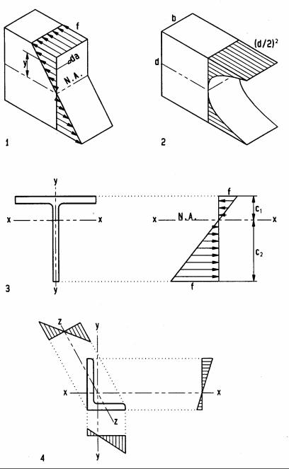
The formula for the moment of inertia I=∫y2da reveals that the resistance of any differential area da increases with its distance y from the neutral axis squared, forming a parabolic distribution. For a beam of rectangular cross-section, the resistance of top and bottom fibers with distance y = d/2 from the neutral axis is (d/2)2. Thus, the moment of inertia, as geometric resistance, is the volume of all fibers under a parabolic surface, which is 1/3 the volume of a cube of equal dimensions, or I= bd (d/2)2/3, or
I = bd3 / 12 (for rectangular beams only)
the moment of inertia of a rectangular beam of homogeneous material. A formal calculus derivation of this formula is given in Appendix A. The section modulus gives only the maximum bending stress, but the moment of inertia gives the stress at any distance c from the neutral axis as f= Mc/I. This is useful, for example, for bending elements of asymmetrical cross-section, such as T- and L-shapes.
1Bending stress distribution over beam cross-section
2Moment of inertia visualized as volume under parabolic surface
3T-bar with asymmetrical stress: max. stress at c2 from the neutral axis
4Angle bar with asymmetrical stress distribution about x, y, and z-axes: maximum resistance about x-axis and minimum resistance about z-axis
6-16 FUNDAMENTALS: Bending
Shear stress
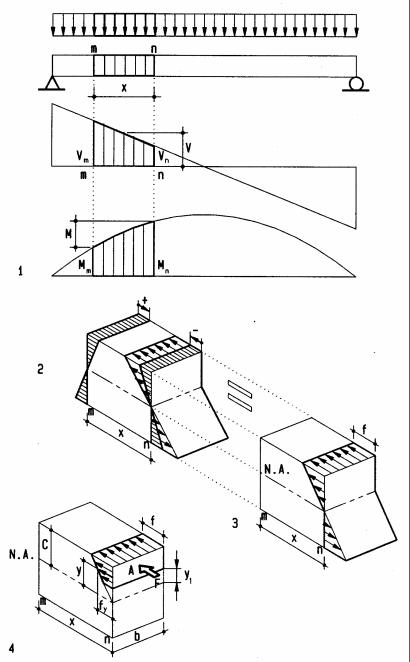
The distribution of shear stress over the cross-section of beams is derived, referring to a beam part of length x marked on diagrams. Even though horizontal and vertical shear are equal at any part of a beam, horizontal shear stress is derived here because it is much more critical in wood due to horizontal fiber direction.
1Beam, shear and bending diagrams with marked part of length x
2Beam part with bending stress pushing and pulling to cause shear
3Beam part with bending stress above an arbitrary shear plane
Let M be the differential bending moment between m and n. M is equal to the shear area between m and n (area method), thus M = V x. Substituting V x for M in the flexure formula f= M c /I yields bending stress f= V x c/I in terms of shear. The differential bending stress between m and n pushes top and bottom fibers in opposite directions, causing shear stress. At any shear plane y1 from the neutral axis of the beam the sum of shear stress above this plane yields a force F that equals average stress fy times the cross section area A above the shear plane, F = A fy. The average stress fy is found from similar triangles; fy relates to y as f relates to c, i.e., fy/y = f/c; thus fy = f y/c. Since f= V x c/I, substituting V x c/I for f yields fy = (V x c/I) y/c = V x y/I. Since F = A fy, it follows that F = A V x y/I. The horizontal shear stress v equals the force F divided by the area of the shear plane;
V = F/(x b) = A V x y/(I x b) = V A y/(I b)
The term A y is defined as Q, the first static moment of the area above the shear plane times the lever arm from its centroid to the neutral axis of the entire cross-section. Substituting Q for A y yields the working formula
v = V Q / (I b) |
(shear stress) |
v = horizontal shear stress.
Q = static moment (area above shear plane times distance from centroid of that area to the neutral axis of the entire cross-section
I = moment of Inertia of entire cross section b = width of shear plane
The formula for shear stress can also be stated as shear flow q, measured in force per unit length (pound per linear inch, kip per linear inch, or similar metric units); hence
q = V Q / I |
(shear flow) |
q = force per unit length |
|
6-18 FUNDAMENTALS: Bending
Shear stress in wood and steel beams
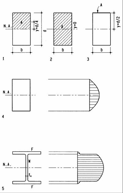
Based on the forgoing general derivation of shear stress, the formulas for shear stress in rectangular wood beams and flanged steel beams is derived here. The maximum stress in those beams is customarily defined as fv instead of v in the general shear formula.
1 |
Shear at neutral axis of rectangular beam (maximum stress), |
|
|
Q = Ay = (bd/2) d/4, or |
|
|
Q = bd2/8 |
(Note: d2 implies parabolic distribution) |
|
I = bd3/12, hence |
|
v = V Q / I b = V (bd2/8) / [(bd3/12)b] = fv, or fv = 1.5 V / (bd)
Note: this is the same formula derived for maximum shear stress before
2Shear stress at the bottom of rectangular beam. Note that y= 0 since the centroid of the area above the shear plane (bottom) coincides with the neutral axis of the entire section. Thus Q= Ay = (bd/2) 0 = 0, hence
v = V 0/(I b) = 0 = fv, thus fv = 0
Note: this confirms an intuitive interpretation that suggests zero stress since no fibers below the beam could resist shear
3Shear stress at top of rectangular beam. Note A = 0b = 0 since the depth of the shear area above the top of the beam is zero. Thus
Q = Ay = 0 d/2 = 0, hence v = V 0/(I b) = 0 = fv, thus fv = 0
Note: this, too, confirms an intuitive interpretation that suggests zero stress since no fibers above the beam top could resist shear.
4Shear stress distribution over a rectangular section is parabolic as implied by the formula Q=bd2/8 derived above.
5Shear stress in a steel beam is minimal in the flanges and parabolic over the web. The formula v = VQ/(I b) results in a small stress in the flanges since the width b of flanges is much greater than the web thickness. However, for convenience, shear stress in steel beams is computed as “average” by the simplified formula:
fv = V / Av
fv = shear stress in steel beam
V = shear force at section investigated
Av = shear area, defined as web thickness times beam depth
6-19 FUNDAMENTALS: Bending
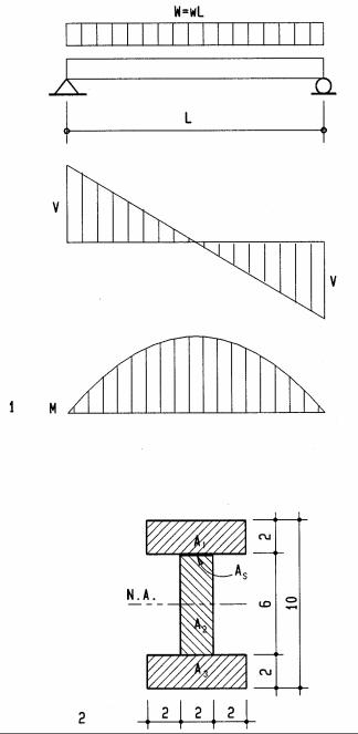
Shear stress in wood I-beam
Since this is not a rectangular beam, shear stress must be computed by the general shear formula. The maximum shear stress at the neutral axis as well as shear stress at the intersection between flange and web (shear plane As) will be computed. The latter gives the shear stress in the glued connection. To compare shearand bending stress the latter is also computed.
1Beam of L= 10 ft length, with uniform load w= 280plf (W = 2800 lbs)
2Cross-section of wood I-beam
Shear force V= W/2 = 2800/2 |
V = 1400 lbs |
Bending moment M=WL/8 = 2800(10)/8 |
M = 3500 lb’ |
For the formula v= VQ/(Ib) we must find the moment of inertia of the entire cross-section. We could use the parallel axis theorem of Appendix A. However, due to symmetry, a simplified formula is possible, finding the moment of inertia for the overall dimensions as rectangular beam minus that for two rectangles on both sides of the web.
I = (BD3– bd3)/12 = [6(10)3– 2(2)63]/12 |
I = 428 in4 |
Bending stress fb= Mc/I = 3500(12)5/428 |
fb = 491 psi |
|
491 < 1450, ok |
Note c= 10/2 = 5 (half the beam depth due to symmetry) |
|
Static moment Q of flange about the neutral axis: |
|
Q = Ay = 6(2)4 |
Q = 48 in3 |
Shear stress at flange/web intersection: |
|
v = VQ/(Ib) = 1400(48)/[428(2)] |
v = 79 psi |
Static moment Q of flange plus upper half of web about the neutral axis |
|
Q = ΣAy = 6(2)4 + 2(3)1.5 |
Q = 57 in3 |
Maximum shear stress at neutral axis: |
|
v = VQ/(Ib) = 1400(57)/[428(2)] |
v = 93 psi <95, ok |
Note: Maximum shear stress reaches almost the allowable stress limit, but bending stress is well below allowable bending stress because the beam is very short. We can try at what span the beam approaches allowable stress, assuming L= 30 ft, using the same total load W = 2800 lbs to keep shear stress constant:
M= WL/8 = 2800(30)/8 |
M = 10500 lb-ft |
fb = Mc/I = 10500(12)5/428 |
fb = 1472 psi |
|
1472 >1450, not ok |
At 30 ft span bending stress is just over the allowable stress of 1450 psi. This shows that in short beams shear governs, but in long beams bending or deflection governs.
6-20 FUNDAMENTALS: Bending
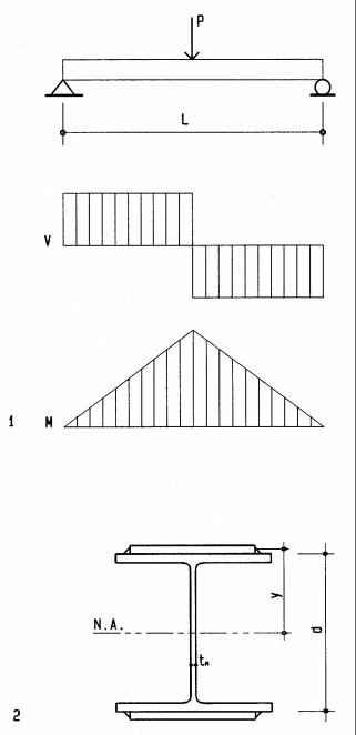
Shear stress in steel beam
This beam, supporting a column point load of 96 k over a door, is a composite beam consisting of a wide-flange base beam with 8x½ in plates welded to top and bottom flanges. The beam is analyzed with and without plates. As shown before, for steel beams shear stress is assumed to be resisted by the web only, computed as fv = V/Av. The base beam is a W10x49 [10 in (254 mm) nominal depth, 49 lbs/ft (6.77 kg/m) DL] with a moment of inertia Ixx= 272 in4 (11322 cm4) (see Appendix). Shear in the welds connecting the plates to the beam is found using the shear flow formula q = VQ/(I).
1Beam of L= 6 ft (1.83 m) span with P = 96 k point load
2Composite wide-flange beam W10x49 with 8x½ inch stiffener plates
Shear force V = P/2 = 96/2 |
V = 48 k |
Bending moment M = 48(3) |
M = 144 k’ |
Wide-flange beam |
|
Shear area of web Av = web thickness x beam depth |
|
Av = 0.34(10) |
Av = 3.4 in2 |
Shear stress fv = V/Av = 48/3.4 |
fv = 14 ksi |
|
14 < 14.5, ok |
Bending stress fb = Mc/I = 144(12)5.5/272 |
fb = 35 ksi |
|
35 >22, not ok |
Since the beam would fail in bending, a composite beam is used. |
|
Composite beam |
|
Moment of inertia I=Σ(Ioo+Ay2) (see parallel axis theorem in Appendix A) |
|
I= 272+2(8)0.53/12+2(8)0.5(5.25)2 |
I = 493 in4 |
Bending stress fb= Mc/I = 144(12)5/493 |
fb = 19 ksi |
|
19 < 22, ok |
Since the shear force remains unchanged, the web shear stress is still ok. |
|
Shear flow q in welded plate connection |
|
Q= Ay = 8(.5)5.25 = 21 in3 |
|
qtot = VQ/I = 48(21)/493 |
qtot = 2 k/in |
Since there are two welds, each resists half the total shear flow |
|
q = qtot/2 |
q = 1k/in |
Assume ¼ in weld of 3.2 k/in * strength |
1 < 3.2, ok |
* see AISC weld strength table |
|
Note: in this steel beam, bending is stress is more critical than shear stress; this is typical for steel beams, except very short ones.
6-21 FUNDAMENTALS: Bending
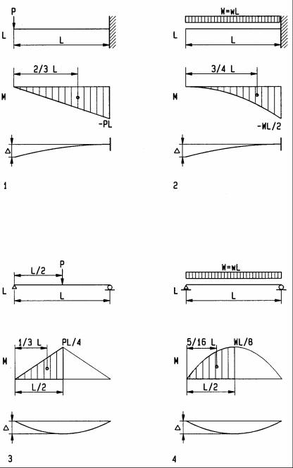
Deflection formulas
Based on the moment-area method, the following formulas for slope and deflection are derived for beams of common load and support conditions. Additional formulas are provided in Appendix A. Although downward deflection would theoretically be negative, it is customary to ignore the sign convention and define upor downward deflection by inspection. The angle θ is the slope of the tangent to the elastic curve at the free end for cantilever beams and at supports for simple beams; ∆ is the maximum deflection for all cases. As derived before, θ is the area of the bending moment diagram divided by EI, the elastic modulus and moment of inertia, respectively; ∆ equals θ times the lever-arm from the centroid of the bending moment diagram between zero and maximum deflection to the point where θ is maximum.
1 |
Cantilever beam with point load; |
θ = (PL)(L/2)/(EI), |
∆= θ 2/3 L |
|
θ= 1/2 PL2/(EI) |
|
|
|
∆= 1/3 PL3/(EI) |
|
|
2 |
Cantilever beam with uniform load; |
θ = (WL/2)(L/3)/(EI), |
∆= θ 3/4 L |
|
θ= 1/6 WL2/(EI) |
|
|
|
∆= 1/8 WL3/(EI) |
|
|
3 |
Simple beam with point load; |
θ = (PL/4)(L/4)/(EI), |
∆= θ 1/3 L |
|
θ= 1/16 PL2/(EI) |
|
|
|
∆= 1/48 PL3/(EI) |
|
|
4 |
Simple beam with uniform load; |
θ = (WL/8)(2/3 L/2)/(EI), |
∆= θ 5/16 L |
|
θ= 1/24 WL2/(EI) |
|
|
|
∆= 5/384 WL3/(EI) |
|
|
6-24 FUNDAMENTALS: Bending
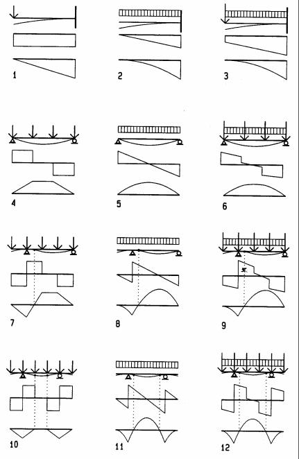
Typical beam diagrams
Deflection, shear, and bending diagrams are shown here for typical beams. The beam with deflection and load diagrams are drawn on top with shear and bending diagrams shown below. With experience, these diagrams may be drawn by visual inspection prior to computing. This is useful to verify computations and develop an intuitive sense and visualization regarding shear and bending on beams. The deflection diagram is drawn, visualizing the deflection of a thin board, flexible ruler, or similar device. It is drawn grossly exaggerated to be visible. The shear diagram is drawn at a convenient force scale left to right, starting with zero shear to the left of the beam. Downward uniform load yields downward sloping shear. Downward point loads are drawn as downward offset, and upward reactions yield upward offset. Bending diagrams are drawn, considering the area method; namely, bending at any point is equal to the area of the shear diagram up to that point. Both, shear and bending must be zero to the right of the right beam end. To satisfy this, requires a certain amount of forward thinking and, in complex cases, even working backward from right to left as well as left to right.
1Cantilever beam with point load
2Cantilever beam with uniform load
3Cantilever beam with mixed load
4Simple beam with point loads
5Simple beam with uniform load
6Simple beam with mixed load
7Beam with one overhang and point load
8Beam with one overhang and uniform load
9Beam with one overhang and mixed load
10Beam with two overhangs and point loads
11Beam with two overhangs and uniform load
12Beam with two overhangs and mixed load
6-27 FUNDAMENTALS: Bending

9
Lateral Force Design
Lateral loads, acting primarily horizontally, include:
•Wind load
•Seismic load
•Earth pressure on retaining walls (not included in this book)
Wind and earthquakes are the most devastating forces of nature:
Hurricane Andrew 1992, with gusts of 170 mph, devastated 300 square miles, left 300,000 homeless, caused about $ 25 billion damage, and damaged 100,000 homes
The 1976 Tangshan Earthquake (magnitude 7.8), obliterating the city in northeast China and killing over 240,000 people, was the most devastating earthquake of the 20th century.
Swiss Re reported 2003 world wide losses:
•60,000 people killed
•Over two thirds earthquake victims
•$70 billion economic losses
IBC table 1604.5. Importance Classification excerpt
Category |
Seismic |
Use Group |
Nature of Occupancy |
Seismic importance factor |
Snow importance factor |
Wind importance factor |
|
||||||
|
|
|
|
|
|
|
I |
I |
|
Low hazard structures: |
1 |
0.8 |
0.87 |
|
|
|
Agriculture, temporary, minor storage |
|
|
|
|
|
|
|
|
|
|
II |
I |
|
Structures not in categories I, III, IV |
1 |
1 |
1 |
III |
II |
|
Structures such as: |
1.25 |
1.1 |
1.15 |
|
|
|
Occupancy >300 people per area |
|
|
|
|
|
|
Elementary schools >250 students |
|
|
|
|
|
|
Colleges >500 students |
|
|
|
|
|
|
Occupancy >5000 |
|
|
|
|
|
|
|
|
|
|
IV |
III |
|
Essential facilities, such as: |
1.5 |
1.2 |
1.15 |
|
|
|
Hospitals, polices and fire stations |
|
|
|
|
|
|
|
|
|
|
9-1 DESIGN METHODS Lateral Force Design