

Architectural Structures
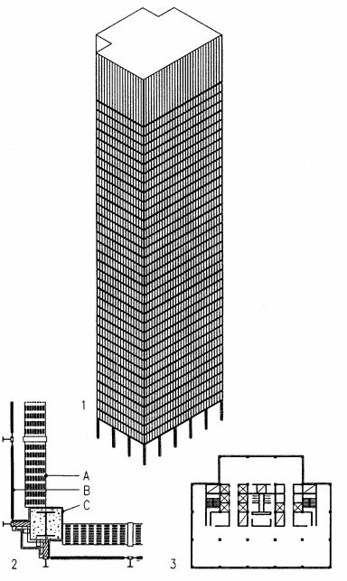
.pdf1Commerzbank Düsseldorf (1965)
Architect: Paul Schneider-Esleben
This 12-story bank building is located at the boundaries between the old and new banking district of Düsseldorf, linked by a pedestrian footbridge to an older building of the bank. The 12-story building above a 2-story podium was initially designed to allow a drive-in bank at street level. A free-standing service core supports the pedestrian bridge and makes the link to the office floors. A second stair and bathroom core is located at the far end of the building, providing undivided and flexible office space. The curtain wall façade is designed and manufactured using vehicular technology of insulating sandwich panels. The structure consists of reinforced concrete. Two rows of square cantilever columns support cantilever beams and concrete floor slabs. The interior core helps to resist lateral load in length and width directions, but the exterior core at the other end of the building resist lateral load in width direction only.
Floor plan: |
16 x 32 m (52 x 104 ft) |
Height: |
44 m (144 ft) |
Typical story height |
3 m (9.8 ft) |
Height/width ratio |
10 per cantilever |
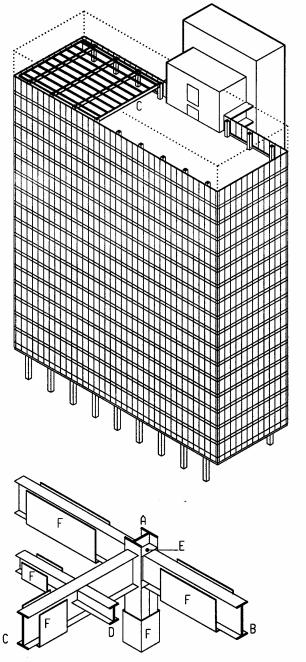
2Lend Lease House Sydney (1961)
Architect: Harry Seidler
This 15-story office tower with north-south orientation of its length axis has movable exterior blinds for sun control. They give the facade an ever-changing appearance. On sunny mid-days, they are horizontal for optimal sun protection. On cloudy days, in lowered position, they tend to darken the inside rooms. The orientation provides inspiring views to the Sydney harbor and a nearby botanical garden. A two-story showroom with mezzanine floor is located on the ground floor, above a four-story underground parking garage. The office floors feature elevators, stair and bathrooms on one end and an exit stair at the opposite end, providing flexible office floors. Mechanical equipment is in a roof penthouse. The structure consists of reinforced concrete. Two rows of wall-shape cantilever columns support cantilever slabs. The cantilever columns resist both gravity and lateral loads.
Floor plan: |
12 x 30 m (39 x 98 ft) |
Height: |
38 m (125 ft) |
Height/width ratio |
4.7 per twin cantilever |
17-5 VERTICAL SYSTEMS Bending Resistant
Moment frame
Moment frames consist of one or more portals with columns joint to beams by moment resistant connections that transmit bending deformation from columns to beam and viceversa. Beams and columns act together to resist gravity and lateral loads in synergy and redundancy. Bending resistance makes moment frames more ductile and flexible than braced frames or shear walls. The ductile behavior is good to absorb seismic energy, but increases lateral drift, a challenge for safety and comfort of occupants, and possible equipment damage.
Moment frames provide optimal planning freedom, with minimal interference of structure. Office buildings that require adaptable space for changing tenant needs, usually use moment frames. To reduce lateral drift in tall buildings, dual systems may include bracing or shear walls, usually at an interior core where planning flexibility is not required. Given the high cost of moment-resistant joints, low-rise buildings may provide only some bays with moment resistant frames. The remaining bays, with pin joints only, carry gravity load and are laterally supported by adjacent moment frames.
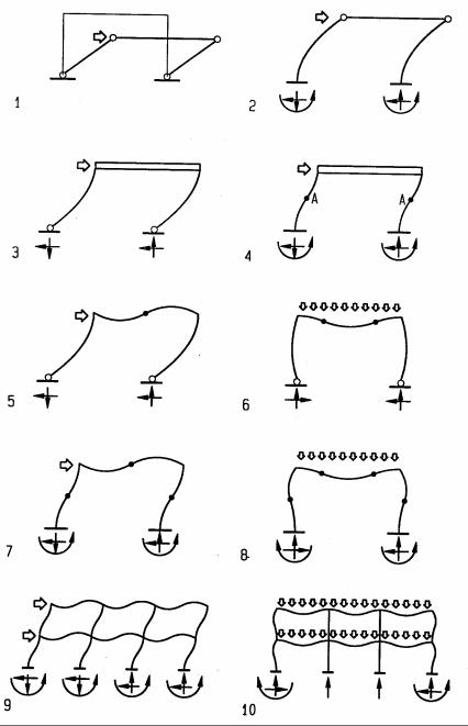
Moment frame behavior can be visualized by amplified deformations. The connection of column to beam is usually perpendicular and assumed to remain so after deformation. Under lateral load, columns with moment joints at both ends assume positive and negative bending at opposite ends, causing S-shapes with inflection points of zero bending at mid-span and end rotation that rotates the ends of a connected beam. By resisting rotation, beams help to resist lateral load. Similarly, a beam subject to bending under gravity load will rotate the columns connected to it and thus engage them in resisting the gravity load. Columns with moment-resistant joints at both ends deform less than columns with only one moment joint. Deformations under gravity and lateral loads are visualized in the diagrams, with dots showing inflection points of zero bending stress.
1portal with hinged joints unable to resist lateral load
2Moment joints at base, hinge joints at beam, large drift
3Moment joints at strong beam, hinge joints at base, large drift
4Moment joints at base and strong beam, drift reduced to half
5Hinged base, moment joints at beam, beam forms inflection point
6Gravity load, hinged base, beam moment joints, 2 beam inflection points
7Lateral load, all moment joints, inflection points at beam and columns
8Gravity load, all moment joints, inflection points at beam and columns
9Multi-bay frame deformation under lateral load
10Multi-bay frame deformation under gravity load
A Inflection point of zero bending stress
17-6 VERTICAL SYSTEMS Bending Resistant
Moment-resistant Joints
Moment-resisting joints usually consist of steel or concrete. They join members (usually column to beam) to transfer bending moments and rotations of one member to the other. The moment resistant connection makes post and beam act in unison to resist both gravity and lateral loads. In seismic regions, moment frames must be ductile to absorb seismic energy without breaking.
Steel moment joints are usually wide-flange beams connected to wide-flange columns. Generally, post and beam are joint about their strong axis. Semi-rigid joints connect the strong beam axis to the weak column axis. Moment resistant joints require stiffener plates welded between column flanges. They resist bending stress of beam flanges that tend to bend column flanges without stiffener plates. Compact columns with very thick flanges do not require such stiffener plates. Steel is a ductile material which is good to absorb seismic energy in the elastic range Yet the seismic performance of steel joints was challenged by failures during the 1994 Northridge Earthquake. The failure resulted primarily from joint welds. Research developed solutions for moment-resisting steel joints, notably dog-bone beam ends to form plastic hinges to reduce stress at the joints.
Concrete frames achieve ductile joints by proper steel reinforcing, designed to yield before the concrete crushes in brittle mode. Usually that implies 25% to 50% less steel and more concrete than used for balanced design (balanced design has just enough reinforcing to balance the concrete strength). Ductile design also requires: closely spaced tie bars near beam/column joints; column rebars to extend through beams; beam rebars to extend through columns; and column ties to continue through beams.
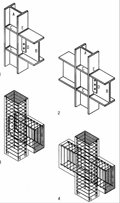
1Moment-resisting steel joint at end column
2Moment-resisting steel joint at interior column
3Moment-resisting concrete joint at end column
4Moment-resisting concrete joint at interior column
ASteel wide-flange column
BSteel wide-flange beam
CStiffener plates resist bending stress of beam flanges
DSteel bar, welded to column in shop and bolted to beam in field
EWeld, joining beam flange to column
FSteel reinforcing bars in concrete beam
GSteel ties to restrain reinforcing bars from buckling
HColumn reinforcing bars to resist compression and bending
17-7 VERTICAL SYSTEMS Bending Resistant
Steel framing
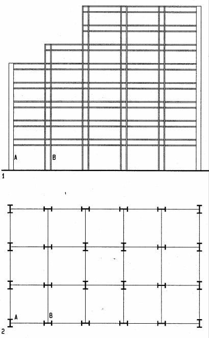
Steel framing with wide-flange profiles requires careful orientation of columns in order to achieve proper strength and stiffness to resist lateral load in both orthogonal directions. Measured by the moment of inertia, typical wide-flange columns have a stiffness ratio of about a 3:1 about the x and y-axis, respectively, yet some deep sections have stiffness ratios up to 50:1, about strong to weak axes. Therefore, column orientation for lateral resistance is an important design consideration for moment frames. Assuming equal lateral load and column size, half of the columns should be oriented in either direction. For unequal loads, column orientations should provide strength proportional to loads. For example a rectangular building has more wind load on the long than on the short facade. If wind governs lateral design, this should be considered in column orientation. Further, column orientation should provide symmetry of stiffness in both directions to prevent torsion. Torsion would occur for example if one end of a building has columns with greater stiffness than the other end. Also to better resist possible torsion from asymmetric mass distribution, columns should be placed near or at the building edge, rather than near the center of mass where they have no effective lever arm to resist torsion. Column size should also account for setbacks on upper floors, to account for asymmetric wind or seismic load resulting from such setbacks.
1Front view of moment resisting frame with setback floors on top
2Column layout in plan for moment resistance in both direction
AColumn oriented for lateral support in width direction
BColumn oriented for lateral support in length direction
17-8 VERTICAL SYSTEMS Bending Resistant
Casa Terragni, Como, Italy (1936)
Architect: Guiseppe Terragni
With 33.2x33.2x16.6m height, the building is a perfect half cube. The plan is organized around a central atrium, surrounded by circulation. Terragni used the concrete moment frame as organizing grid in a liberal manner, modified as required to meet planning needs: the 4.75m grid is reduced for circulation and increased for large spaces. Beams of variable depth express the respective spans. The front facade is recessed behind a veranda to emphasize the frame. Moment frames with shear walls have proven a failsafe solution in earthquakes prone areas: shear walls provide good stiffness under moderate load, and the moment frame provides ductility if shear walls fail in sever earthquakes.
Commonwealth (formerly Equitable) Building (1947-48)
Architect: Pietro Belluschi
The Equitable Building 1948 pioneered the clear expression of a steel moment frame, a model for many subsequent buildings. With this building Beluschi also pioneered the first double glazed aluminum curtain wall of simple elegance.. The building is a National Historic Landmark of mechanical engineering because it was the first building using heat pumps for efficient air conditioning.. It was the first skyscraper to use double-paned glass. The first building with air conditioning, completely sealed The first to use a flush curtain wall design. The first to be clad completely in aluminum. In 1982 the American Institute of Architects awarded it the building its 25 year award. The building is a compelling testimony of Beluschi’s philosophy of simplicity.
.
17-9 VERTICAL SYSTEMS Bending Resistant
Seagram building, New York (1954-58)
Architect: Mies van der Rohe, Philip Johnson, Kahn and Jakobs Engineer: Severud, Elstad, Krueger
The 38-story Seagram building is a classic icon of modem architecture. It was the result of unique cooperation between the client, Samuel Bronford, his daughter, Phyllis Lambert as planning director, and the architects. The building exemplifies Mies' philosophy of Baukunst (art and craft of building), with great attention to detail and proportion. The structure, based on a 28 ft (8.5 m) module, is expressed as colonnade at the base to signal the entrance. The skin of the mechanical floor on top provides a visual cap. Most of the structure is concealed behind the curtain wall which eliminates thermal stress and strain due to outside temperature variations, an important factor in tall structures. The recessed rear gives the tower its classic proportions of five to three for front and side, respectively. The steel moment frame structure is embedded in concrete for fire protection and added stiffness. The core walls have diagonal bracing up to the 29th floor for additional wind bracing. Concrete shear walls up to the 17th floor provide additional stiffness.
Floor plan: |
84 x 140 feet (26 x 43 m) without extrusion |
Height: |
525 feet (160m) |
Typical story height: |
13.6 feet (4.15m) |
Height/width ratio |
6.3 without extrusion |
1Axon view of tower
2Comer detail of structure and skin
3Typical plan with recessed comers to express 3 to 5 proportion
AAir conditioning duct as parapet
BGlare reducing pink glass appears without color from inside
CBronze cover of steel column embedded in concrete
17-10 VERTICAL SYSTEMS Bending Resistant
Crown Zellerbach building, San Francisco (1959)
Architect: SOM and Hertzka and Knowles Engineer: H. J. Brunnier
The 20-story Crown Zellerbach headquarters building covers about one third of a triangular site on Market Street, the main street of San Francisco. The building features a large office wing flanked by an external core for stairs, elevators, bathrooms, and mechanical ducts. The exterior core gives the office wing a column-free floor area for optimal space planning flexibility. A planning module of 5.5 feet (1.6 m) provided for good size office spaces.
The structure is a moment resistant steel frame with wide-flange girders spanning 63 feet (19 m) across the width of the building, supported by wide-flange columns, spaced 22 feet (6.7 m) on center. Spandrel beams connect the columns in the longitudinal direction. Steel joists, spaced 7 feet (2.1 m), support concrete slabs on cellular metal decks. The joists cantilever at each end of the building. All columns are oriented with their strong axis to provide moment resistance in the width direction, giving the building much greater strength and stiffness in width than in length direction. Since the building is much longer than wide, the column orientation is good for wind load which is greater on the long faced; but it is less effective for seismic load which is greater in length direction. Also the eccentric service tower causes seismic torsion. The fire exits on both side of the service tower are too close together for fire safety and would not be allowed by current code. The building is supported by a mat foundation, 8 feet (2.4 m) deep, extending the full width and length of the building. The foundation rests on firm soil 45 feet (13.7 m) below grade under a 2-story parking garage. The steel structure is protected by fire proofing that consists of stucco applied to metal lath wrapped around beams and columns.
Floor plan: |
201x69 ft (61x21m) without exterior core |
Height: |
320 ft (96m) |
Typical story height: |
13.67 ft (4m) |
Height/width ratio |
4.6 without exterior core |
AColumn spaced 22ft (6.7 m)
BSpandrel beam
CGirder spanning the full width of the building
DJoist spaced 7ft (2.1 m)
EStiffener plate for moment connection
FFire proofing on metal lath
17-11 VERTICAL SYSTEMS Bending Resistant
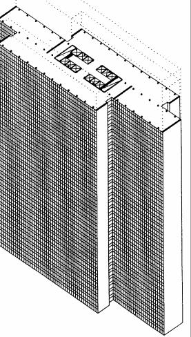
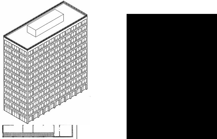
Thyssen tower, Düsseldorf (1957-60)
Architect: Hentrich and Petchnigg Enginer: Kuno Boll
The Thyssen tower’s unique plan of three slabs is a composition with efficient circulation and good delighting for all offices that are never more than 7m (23 ft) from a window. The floor area of offices is 62,7% of the gross floor area. Located at the center of town, the long axis is oriented north-south with a park to the North. The central block includes the service core and, as tallest block, houses mechanical and elevator equipment in the top floors of this 25-story tower. Parking for 280 cars is in the underground garage, rapped around the building. The long facades feature glass curtain walls; the narrow end facades are glad in stainless steel. The steel frame structure is embedded in concrete for fire protection and to provide additional stiffness. The columns consist of steel pipes produced by the building owner. The structural module is 7x4.2 m (23x14 ft), with some variation between central and outer slabs. Braced end walls provide some additional stiffness to resist wind load on the long building sides. The exterior composition of the building, expressing the internal organization, has earned the nickname “Drei-Scheiben Haus” (Three-slab-house). The pristine design, combining American know-how with European sophistication stands as an icon of the modern movement in Europe.
Floor plan: |
21x80 m (70x226 feet) |
Height: |
94 m (308 feet) |
Typical story height: |
12.2 feet (3.7 m) |
Height/width ratio |
4.48 |
17-12 VERTICAL SYSTEMS Bending Resistant
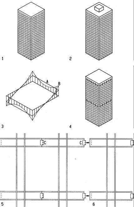
Framed Tube
Framed tubes are a variation of moment frames, wrapping the building with a “wall” of closely spaced columns and short spandrel beams. To place the lateral resistance system on the façade rather then at the interior gives it a broader base for greater stability as well as improved rotational resistance. In addition, the lateral resisting system on the façade allows smaller columns on the interior to carry gravity load only. Further, designing floors and roof to span the full width of a building can make the interior completely column free for optimal flexibility. A major challenge of framed tubes is the high cost of numerous moment resistant joints between closely spaced columns and beams. To minimize this adverse cost factor, designers often use prefab methods to weld the joints in the fabrication hop rather than on the job site. This process also improves quality control and reliability.
1Framed tube without interior core
2Framed tube with interior core
3Global stress diagram of framed tube
4Framed tube with belt and top truss for additional stiffness
5Prefab frame with joints located at beam inflection point of zero bending
6Prefab element ready for assembly
AReduced shear resistance (shear lag) at hollow interior
BPeak axial force from overturn moment
CPin joint at inflection point of zero beam bending stress
17-13 VERTICAL SYSTEMS Bending Resistant
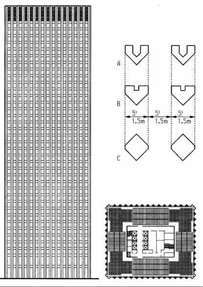
CBS Tower New York (1961-650
Architect: Eero Saarinnen
Engineer: Paul Weidlinger
The 38-story CBS tower is a stark vertical extrusion of the rectangular floor plan. Columns forming a framed tube are expressed as triangular extrusions on the upper floors and diamond shaped on the ground floor. The triangular columns include niches for mechanical ducts and pipes. The niches decrease from top to bottom with the decreasing duct sizes that run down from the mechanical room on the top floor. The decreasing niches result in increasing net column size that coincides with increasing load as it accumulates from top down. Concrete floors span between the walls of a central core and the framed tube, providing a column-free donut-shape floor space for flexible use. The four sides facing the core feature one-way rib slabs, but the four corners have two-way waffle slabs, designed to make the transition from one direction to the other. Glad in black granite the closely spaced triangular columns express a stark verticality, perforated with regular windows on all but the top and ground floors. The top mechanical floor has ventilation louvers instead of windows, the ground floors have taller windows and doors. The articulation of top and bottom of the façade emphasizes the most prominent part of the building, a strategy often use for the design of tall buildings.
Floor plan: |
155x125 feet (47x38m) |
Height: |
494 feet (151m) |
Typical story height: |
12 feet (3.66m) |
Floor-to-ceiling height: |
8.75 feet (2.67m) |
Height/width ratio |
3.9 |
AColumn profile at top floor
BColumn profile at lower floors
CColumn profile at ground floor
17-14 VERTICAL SYSTEMS Bending Resistant