

Architectural Structures
.pdfWorld Trade Center, New York (1977 (demolished by terrorists 9-11-2001)
Architect: Minoru Yamasaki and E. Roth Engineer: Skilling, Helle, Jackson, Robertson
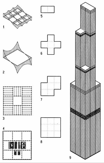
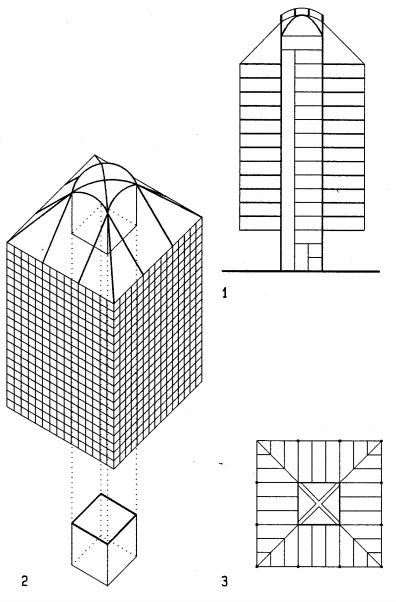
The World Trade center of two 110-story towers and related smaller structures housed 50,000 employees and up to 80,000 visitors daily. Both towers, in diagonal juxtaposition, were vertical extrusions of square plans, with very closely spaced steel columns. Each tower had two-story mechanical spaces on top, near the bottom, and two distributed at 1/3 intervals, with elevator sky-lobbies two floors above each. Each tower had 100 passenger and four service elevators. Each sky-lobby was reached by 11 or 12 elevators from ground floor; with five express elevators non-stop to the 107th and 110th floors. Since elevators are stacked, 56 shafts needed, take 13% floor area on each floor. The framed tube structure consisted of 56 box steel columns on each façade, joint at each floor by spandrel beams with moment resistant connections. This giant Vierendeel frame was assembled from prefab elements of three two-story columns with beam and column joints at mid-span and mid-height where inflection points of zero bending occur under lateral load. Combined with rigid floor diaphragms, the towers formed torsionresistant framed tubes that cantilever from a five-story underground structure that houses train and subway stations as well as parking for 2,000 cars. Although the framed tube column’s overall dimensions are constant, their wall thickness increases from top to bottom in response to increasing loads. Floor truss joists span from the framed tube to columns around the central core. Mechanical ducts run between truss joists for reduced story height. The core columns are designed to carry gravity load only. The framed tube resisted both lateral and gravity load.
Floor plan (square): |
208x208 feet (63.4x63.4 m) |
Height: |
1361 feet (415m) |
Typical story height: |
12 feet (3.66m) |
Floor-to-ceiling height |
8.6 feet (2.62m) |
Height/width ratio |
6.5 |
1Axon of tower
2Typical floor framing plan
3Typical prefab two-story façade assembly
4Typical framed tube column size and spacing
17-15 VERTICAL SYSTEMS Bending Resistant
Bundled Tube
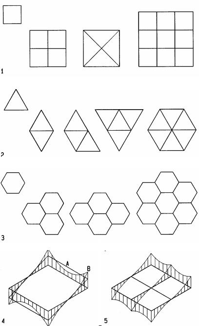
Bundled tube structures are composed of tubes framed by closely spaced columns joined to beams to form moment frames. The bundled tubes resulting from the rows of columns add lateral resistance to the structure, transferring shear between exterior columns subject to tension and compression under lateral load. This shear transfer makes it possible for the exterior columns to act in synergetic unison, whereas independent columns would act alone to provide much less lateral resistance. Bundled tubes transfer shear not only through exterior frame “walls” but also through interior cell “walls.” To reduce shear lag.
An alternative to framed bundled tube are braced bundled tube systems. However, though they provide greater stiffness, the braces disrupt spatial flow between interior columns. Regarding plan geometry, bundled tubes may have bundles of square, rectangular, or triangular polygons that are repeatable. However, hexagonal polygons would be less efficient
1Square tube modules
2Triangular tube modules
3Hexagonal tubes would be less effective to reduce shear lag
4Framed tube shear lag
5Bundled tube with reduced shear lag
AShear lag between connecting shear walls
BPeak resistance at shear wall
17-16 VERTICAL SYSTEMS Bending Resistant
Sears tower, Chicago (1973)
Architect/ Engineer: Skidmore, Owings and Merrill
With 110 stories, the Sears Tower was the tallest building in the world for many years and occupies an entire city block on the southwest of Chicago’s loop. The tower starts at ground level with nine square modules of 75 feet (22.9m) each. The nine modules gradually reduce to a twin module on top in response to needed office space and also to reduce wind resistance and overturn moments. The large areas of the lower floors are occupied by Sears, the smaller floors at higher levels serve smaller rental needs. Elevators serve the building in three zones of 30 to 40 stories separated by sky-lobbies that are reached by double deck elevators express elevators. The building façade is glad in black aluminum and tinted glass. The structure is anchored to a five-story underground structure. Nine bundled tubes are separated by rows of columns, spaced 15 feet (4.6m) on center. The columns, welded to beams, form moment resisting portals to transfer global shear under lateral load from compressed to tensed side of the structure, to reduce lateral drift. This shear transfer between exterior walls reduces “shear lag” and gives the bundled tube greater strength and stiffness to resist lateral loads. The bundled tube concept conceived facilitates the setbacks as the floors get smaller toward the top. Belt trusses at three levels in conjunction with mechanical floors reduce lateral deflection by about 15 percent and help distribute uneven gravity load caused by floor setbacks. The horizontal floor framing consists of trusses that span 75 feet (23m) between columns and support concrete slabs on metal deck. The one-way floor trusses of 40 inch (1m) depth change direction every 6th floor to redistribute the gravity load to all columns. Trusses consist of top and bottom T-bars, connected by twin angle web bars. They allow mechanical ducts between top and bottom chords. The small truss depth was possible, using composite action; shear studs engage the concrete slab in compression for increased resistance.
Floor plan at ground: |
225 x 225 feet (69 x 69m) |
Height: |
1,450 feet (442m) |
Typical story height: |
13 feet (3.96m) |
Height/width ratio |
6.4 |
1Tower axon
2Base floor plan
3Floor framing
4Stress diagram of single framed tube with shear lag between walls
5Stress diagram of bundled tube with reduced shear lag
6Floor plan at ground floor
7Floor plan starting at 51st floor
8Floor plan starting at 66th floor
9Floor plan of top floors
17-17 VERTICAL SYSTEMS Bending Resistant
19
Vertical Systems
Suspended
Vertical systems, suspended, also referred to as suspended high-rise structures, are different from suspension structures like suspension bridges, which are draped from two suspension points; suspended high-rise structures hang usually about vertically from top. A rational for suspended high-rise structures is to free the ground floor from obstructions. Other architectural and structural reasons are described on the next page.
Regarding Lateral load, the challenge of suspended high-rise is usually a narrow footprint and slender aspect ratio. Thus their behavior is comparable to a tree, where the drunk resists load primarily in bending and large roots are required to resist overturning. Properly designed, the narrow aspect ratio can enhance ductility to make the structure behave like a flower in the wind to reduce seismic forces.
19-1 |
VERTICAL SYSTEMS Suspended |
Suspension rational
At first glance suspended high-rise structures seem irrational, given the load-path detour: gravity load travels to the top and then down to the foundation. However, as described below, there are advantage, both architectural and structural, that justify this detour. Understanding the pros and cons and their careful evaluation are essential for design.
Challenges
•Load path detour: load travels up to the top, then down to foundation
•Combined hanger / column deflection yields large differential deflection
Architectural rational
•Less columns at ground floor provides planning flexibility and unobstructed view
•Facilitates top down future expansion with less operation interference
•Small hangers instead of large columns improve flexibility and view
Structural rational
•Eliminates buckling in hangers, replacing compression with tension
•High-strength hangers replace large compression columns
•Floors may be built on ground and raised after completion
•Concentration of compression to a few large columns minimizes buckling
Design options
•Multiple towers with joint footing to improve overturning resistance
•Multiple stacks to limit differential deflection
•Adjust hangers for DL and partial LL to reduce deflection
•Prestress hangers to reduce deflection to half
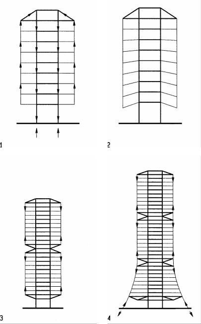
1Gravity load path
Load travels to top, then down to foundation
2Differential deflection is cumulative
Shortening of columns and elongation of hangers are additive
3Prestress can reduce deflection to half
Top resists half the load through increase of prestress Bottom resists half the load through decrease of prestress
4Ground anchors for improved stability (assuming hangers as ground anchors are ok)
19-2 |
VERTICAL SYSTEMS Suspended |
Design options
Suspended high-rise structures may be designed in various configurations with distinct limitations and implications regarding behavior. The following description provides guidelines for rational design, starting with the introduction of a terminology, followed by implications of various design options:
•Single towers (one vertical support)
•Multiple towers (several vertical supports)
•Single stacks (one set of floors)
•Multiple stacks (several sets of floors)
The effect of these options are described and illustrated as follows:
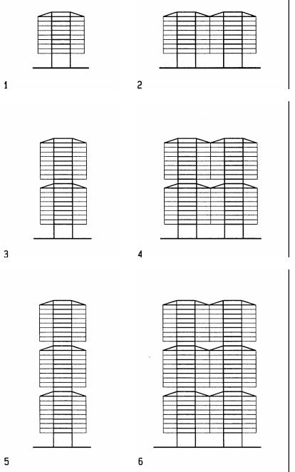
1Single tower / single stack
Single towers require large footing like a tree to resist overturning
2Multi towers
Multiple towers with joint footing increase stability
3Twin stacks
Twin stacks reduce the length of hangers an thus differential deflection Max. ten stories per stack limits differential deflection to < 2 inch (50 mm)
4Twin stacks / towers
Twin stacks reduce the length of hangers an thus differential deflection Twin towers with joint footing increase stability
5Triple stacks
Three or more stacks limit hanger length and thus differential deflection
6Triple stacks / twin towers
Three or more stacks limit hanger length and thus differential deflection Two or more towers with joint footing increase stability
Limits
An important limit for suspended high-rise structures are the limited number of floors per stack. More than ten floors per stack would cause unacceptable differential deflections. Conventional columns in compression are subject to about equal strain under load. Suspended high-rise structures are subject to greater differential deflection since hangers elongate but columns shorten under gravity load. Without buckling, the high tensile stress of hangers causes greater strain which further increases differential deflection.
19-3 |
VERTICAL SYSTEMS Suspended |
Case studies
Westcoast Transmission Tower, Vancouver (1969)
Architect: Rhone and Iredale Engineer: Bogue Babicki
The 12-story tower, initially designed and built as Westcoast Transmission headquarters, has become an architectural icon of Vancouver. With support of the City of Vancouver, the historically significant building was converted in 2005 to 180 unique residential suites in studio, one and two bedroom configurations. The suspension concept was selected to provide an unobstructed view to the beautiful bay of Vancouver. According to the Bogue Babicki, the suspension option was also more economical than a conventional alternative they had considered. The suspended structure, stating 30 feet (9 m) above grade provided unobstructed views at ground level to the beautiful bay of Vancouver. The tower is supported by a site-cast concrete core, 36 feet (11 m) square. The floors are suspended by 12 cables. Each cable consists of two 2 7/8” (73 mm)diameter strands. The sloping guy cables have two additional 2 ½” (64 mm) diameter strands (the 45 degree slope increased their vector force by 1.414).
Size: |
|
108x108 feet (33 x33 m) |
Core size: |
36x 36 feet (11x11 m)) |
|
Height |
12 stories, 224’ (68 m) |
|
Typical story height: |
12 feet (3.65 m) |
|
Core height/width ratio: |
6.2 |
|
1 |
Section |
|
2 |
Exploded axon |
|
3 |
Floor framing |
|
19-4 |
VERTICAL SYSTEMS Suspended |
BMW Headquarters Munich (1972)
Architect: Karl Schwanzer
Engineer: Helmut Bomhard
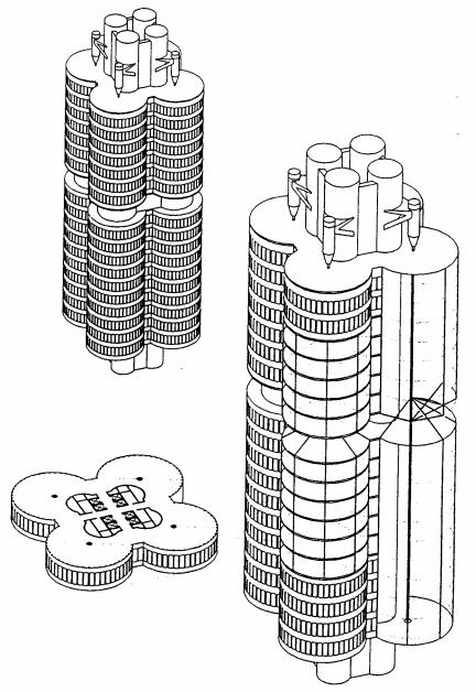
The Viennese architect Karl Schwanzer won the international design competition for the BMW tower with his idea to represent the automobile company in form of a four-cylinder engine. Four cylinders are suspended from an assembly of four semi-cylindrical concrete cores by means of hangers, suspended from a concrete cores of stairs, elevators, etc. The core extends as four cylinders on top of the floor stacks. Each floor is supported by a hanger at its center and stabilized by the core. To keep differential deflection within acceptable limits, the tower is partitioned into two stacks of eleven and seven office floors of the lower and upper stacks, respectively. Eight elevators, stairs and services are located in the core. Except for the four central hangers, the office space around the core is free from columns to provide highly flexible office areas. Construction of the tower started with the central core in conventional method; but then proceeded from top down. Post-tensioned concrete floor plates, cast on the ground, where lifted up by hydraulic means; starting with the top floor, followed by successive floors downward. Silver gladding exterior conveys a sophisticated high-tech image, true to the BMW philosophy.
Size: |
52,30 m (172 feet ) diameter |
Core size |
24.4 m (80 feet) |
Height: |
18 suspended stories, 101 m (331 feet) |
Typical Story height: |
3.82 m (10.8 feet) |
Core height/width ratio: |
4.1 |
19-5 |
VERTICAL SYSTEMS Suspended |
Standard Bank Center, Johannesburg (1968)
Architect: Hentrich and Petschnigg
Engineer: Ove Arup and Partners
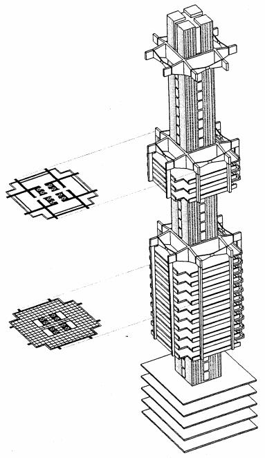
The Standard Bank Center is located in the financial center of Johannesburg. Given the dense surroundings, the design objective was to access the center via an open plaza with the least amount of bulk and obstructions. The response to this objective was a suspended structure. The central support core only at ground level, kept the plaza level open for free and spacious access. The suspension system also facilitated construction at the dense urban surrounding. After the central core was built, floors were suspended from three cantilevers. To limit differential deflection, the building is organized into three stacks of nine office floors each, suspended from concrete cantilever beams of 18 feet (5.4 m) depth. The cantilever beams are attached to the outside face of the concrete core by shear connection. The cantilever floors house the mechanical equipment and transformer stations. Basement floors for computer rooms and parking provide stability for the central core.
Floor size: |
112x112 feet (34.29x34.28 m) |
Core size: |
48x48 feet (14.63x14.63 m) |
Building height: |
27 stories, 456 feet (139 m) |
Core height: |
520 feet (158.5 m) |
Core height/width ratio: |
10.8 |
19-6 |
VERTICAL SYSTEMS Suspended |
Hon Kong and Shanghai Bank (1986)
Architect: Norman Foster Engineer: Ove Arup
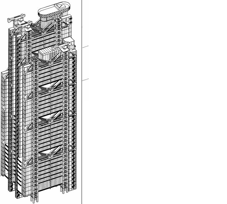
The design of the Hong Kong and Shanghai Bank emerged from a competition among seven invited architects. Foster's winning scheme is a suspension system intended to provide large public space at ground level without interior columns. The large floor area of 55x70m (180'x230') is supported by 8 Vierendeel towers, each consisting of four round columns spaced 5.1x4.8 m (17'x16’) and connected at each level with tapered beams. The floors are suspended from twin suspension trusses which span the towers and cantilever from them on both sides to support service modules and exit stairs. A large floor area of 33.6x55 m (110'x180') between the towers are disrupted by only eight hangers, an additional benefit of the suspension scheme, besides the open ground floor. The space between two-story high suspension trusses serves as focal point of each stack of floors, as reception, conference and dining areas and lead to open recreation terraces with dramatic views of Hong Kong.
The maximum mast pipe diameter is 1400 mm (55”0 and 100 mm (3.9”) thick The maximum hanger pipe diameter is 400 mm (16”) and 60 mm (2.4”) thick
|
|
|
19-7 |
VERTICAL SYSTEMS Suspended |
|