

Architectural Structures
.pdfBraced /moment frame
Combined braced/moment frames are used to reduce drift under lateral load. Moment frames have the greatest drift at the building base, but braced frames have the greatest drift on top. Combining the two systems reduces drift at both base and top. The objectives to reduce drift are:
• To prevent occupant discomfort
• To reduce the risk of failure of cladding and curtain walls
• To reduce secondary stress caused by P-∆ effects
(the P-∆ effect generates bending moments caused by column gravity load P and the lateral drift ∆ as lever arm)
1 Bending resistance of moment frame portal under lateral load 2 Axial resistance of braced frame portal under lateral load
3 Lateral drift of moment frame is maximum at base 4 Lateral drift of braced frame is maximum on top 5 Reduced drift of combined braced/moment frame
5
15-6 VERTICAL STRUCTURES General Background

Structure systems
The vertical-lateral framing systems of wall, cantilever, braced frame, and moment resisting frame, shown from left to right, may be optimized for height and use, including combinations of systems. The importance to select an efficient system increases with building height in order to achieve a low weight per floor area ratio for the structure. The late engineer Fazlur Kahn of Skidmore Owings and Merrill recommended the following systems for various heights:
Concrete moment resisting frame |
20 stories |
Steel moment resisting frame |
30 stories |
Concrete shear wall |
35 stories |
Braced moment resisting frame |
40 stories |
Belt truss |
60 stories |
Framed concrete tube |
60 stories |
Framed steel tube |
80 stories |
Braced tube |
100 stories |
Bundled tube |
110 stories |
Truss tube without interior columns |
120 stories |
1Cellular shear walls
2Exterior shear walls
3Curved shear walls
4Cantilever core with cantilever floors
5Cantilever round core with cantilever floors
6Cantilever core with suspended floors
7Moment resistant frame
8Moment frame with two shear cores
9Moment frame with single shear core
10Braced core
11Braced exterior bays
12Braced core with outrigger trusses
15-7 VERTICAL STRUCTURES General Background

Tubular systems incorporate lateral resistance into the skin by either some form of bracing or narrowly spaced columns with moment resisting beam-column connections. For very tall buildings, bundled tubes increase lateral resistance with interior cell “walls” to reduce shear lag between exterior skin bracing. The Sears tower in Chicago has a framed bundled tube structure.
1 Framed tube
2 Braced tube
3 Bundled tube, framed
4 Bundled tube, braced
1
3
15-8 VERTICAL STRUCTURES General Background
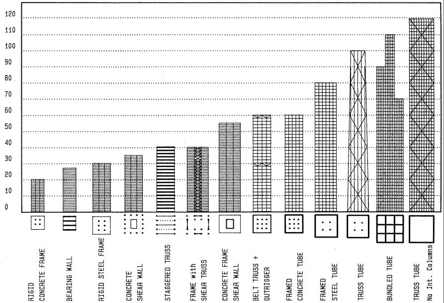
Structure systems vs. height
The diagram is based on a study by the late Fazlur Kahn regarding optimal structure system for buildings of various heights, defined by number of stories.
15-9 VERTICAL STRUCTURES General Background

Structure weights
The amount of structural steel required per floor area is a common measure of efficiency for steel structures. Comparing various systems demonstrates the importance of selecting a suitable system. As shown in the diagram, considering gravity load alone, the structural weight would increase only slightly with height. The effect of lateral load, however, accelerates the increase dramatically and at a non-linear rate.
1Structural steel weight related to building height (by Fazlur Kahn)
2Weight of structural steel per floor area of actual buildings
ANumber of stories
BWeight of structural steel in psf (pounds per square foot)
CWeight of structural steel in N/m2
DWeight of structural steel considering floor framing only
EWeight of structural steel considering gravity load only
FWeight of structural steel for total structure optimized
GWeight of structural steel for total structure not optimized
HEmpire State building New York
IChrysler building New York
JWorld Trade center New York
KSears tower Chicago
LPan Am building New York
MUnited Nations building New York
NUS Steel building Pittsburgh
OJohn Hangkock building Chicago
PFirst Interstate building Los Angeles
QSeagram building New York
RAlcoa building Pittsburgh
SAlcoa building San Francisco
TBechtel building San Francisco
UBurlington House New York
VIDS Center Minneapolis
WKoenig residence Los Angeles
15-10 VERTICAL STRUCTURES General Background
Beam-column interface
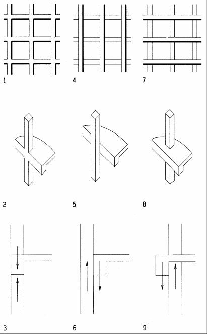
The type of interface between spandrel beam and column on a facade is important considering architectural and structural implications. Assuming moment resisting connections, the best structural solution is to frame the beam directly into the column for effective moment transfer without torsion. If shown on the facade, this expresses most clearly a moment resisting frame. Beams may run behind the column to express verticality, or in front of the column to express horizontally; yet both cases generate torsion in the beam and bending in the column due to eccentricity.
1Visual expression of frame
2Axon of beam framed directly into column
3Section of beam framed directly into column
4Visual expression of columns
5Axon of beam running behind column
6Section of beam running behind column yielding a moment couple
7Visual expression of beam
8Axon of beam running in front of column
9Section of beam running in front of column yielding a moment couple
15-12 VERTICAL STRUCTURES General Background
17
VERTICAL SYSTEMS
Bending Resistant
Bending resistant structures include cantilever, moment frame, framed tube, and bundled tube structures. They resist lateral load by combed axial and bending stresses. Since bending stress varies from tension to compression with zero stress at the neutral axis, only half the cross section is effectively engaged. This makes them less stiff than shear walls or braced frames, but it provides greater ductility to absorb seismic energy in the elastic range, much like a flower in the wind. On the other hand, bending resistance implies large deformations that may cause damage to non-structural items. Bending resistant structures are sometimes combined with other systems, such as braced frames or shear walls, for greater stiffness under moderate load; but moment frames provide ductility under severe load, after the bracing or shear walls may fail.
17-1 VERTICAL SYSTEMS Bending Resistant

Cantilever
Cantilever structures consist of towers that rise from the foundation. They resist gravity load in compression and lateral load in bending and shear, similar to moment frames. Cantilevers are subject to global bending of the entire tower, whereas moment frames are subject to localized bending of columns and beams joint by moment resistant joints. The global bending of cantilever towers increases from minimum on top to maximum at the base; whereas the local bending of beams and columns in moment frames varies at each level from positive to negative.
Cantilever towers may be very slender walls, hollow boxes, or solid columns. But compared to shear walls which resist lateral load primarily in shear, cantilevers resist primarily in bending. The most common materials are reinforced concrete and wood poles of pole houses. Floors may also cantilever from the towers. Cantilevers need large foundations to resist overturn moments. Cantilever systems of multiple towers may have joint foundations that tie the towers together for better stability.
1Single tower cantilever with cantilever floors
2Single tower cantilever under lateral load
3Twin tower cantilever with joined footing for improved stability
4Twin tower cantilever under lateral load
5Single tower cantilever with suspended floors
6Single tower suspension cantilever under lateral load
17-2 VERTICAL SYSTEMS Bending Resistant

Pirelli tower, Milan (1956-58)
Architect: Ponti, Fornaroli, Rosselli, Valtolina, Dell Orto Engineer: Arturo Danusso, Pier Luigi Nervi
Facing Milan’s central station across a major urban plaza, the 32-story Pirelli tower rises prominently above the surrounding cityscape. A central corridor, giving access to offices, narrows toward both ends in response to reduced traffic. The reinforced concrete structure features two twin towers in the midsection for lateral resistance in width direction and triangular tubes at both ends for bilateral resistance. The towers and tubes also support gravity load. The gravity load of the towers improves their lateral stability against overturning. The central towers are tapered from top to base, reflecting the increasing global moment and gravity load. The towers are connected across the central corridors at each level by strong beams that tie them together for increased stability. In plan, the central towers are fan-shaped to improve buckling and bending resistance. The tubular end towers of triangular plan house exit stairs, service elevators, and ducts. Concrete rib slabs supported by beams that span between the towers provide columnfree office space of 79 and 43 ft (24 and 13 m). The plan and structure give the tower its unique appearance, a powerful synergy of form and structure.
Floor plan: |
18 x 68 m (59 x 223 ft) |
Height: |
127 m (417 ft)) |
Typical story height: |
3.9 m (12.8 feet) |
Height/width ratio |
7 |
17-3 VERTICAL SYSTEMS Bending Resistant

Hypo Bank, Munich (1980)
Architect: Bea and Walter Betz
The design objective for the Hypo Bank headquarter was to create a landmark for Munich and a unique architectural statement for the bank. Built 1980, the 22 story bank has 114m height. The structure consist of four tubular concrete towers that support a platform which supports 15 floors above and 6 floors suspended below. The suspended floors had been built from top down simultaneous with upper floors being built upwards. Four towers combined with a platform form a mega-frame to resist gravity and lateral loads. The four towers include exit stairs in prestressed concrete tubes of 7m diameter and 50 to 60 cm wall thickness. A fifth tower of 12.5m diameter, houses eight elevators and mechanical equipment. The support platform consist of prestressed site-cast concrete of 50cm thick concrete slabs on top and bottom, joined by 1.5m rib walls that are tied around the towers. The formwork for the platform was assembled on ground and lifted 45 m by 12 hydraulic jacks.
The office space consists of three triangular units, joined by a T-shaped center. Two-way beams for office floors are supported by columns above the platform and suspended below. Three sub-grade levels include parking, security control, and loading stations.
Floor plan: |
7 m ( 23 ft) diameter towers |
Height: |
114 m (374 ft) |
Height/width ratio |
16 per tower |
1Typical upper floor supported by columns above the platform
2Story-high platform forms a mega frame with four towers
3Typical lower floor suspended from the platform
4Isometric view of building
5Roof plan
6Typical office floor framing
7Support platform framing
8Typical floor plan layout
17-4 VERTICAL SYSTEMS Bending Resistant