

Architectural Structures
.pdfBraced frames
Braced frames resist gravity load in bending and axial compression, and lateral load in axial compression and tension by triangulation, much like trusses. The triangulation results in greater stiffness, an advantage to resist wind load, but increases seismic forces, a disadvantage to resist earthquakes. Triangulation may take several configurations, single diagonals, A-bracing, V-bracing, X-bracing, etc., considering both architectural and structural criteria. For example, location of doors may be effected by bracing and impossible with X-bracing. Structurally, a single diagonal brace is the longest, which increases buckling tendency under compression. Also the number of costly joints varies: two for single diagonals, three for A- and V-braces, and five joints for X-braces. The effect of bracing to resist load is visualized through amplified deformation as follows:
1Single diagonal portal under gravity and lateral loads
2A-braced portal under gravity and lateral load
3V-braced portal under gravity and lateral load
4X-braced portal under gravity and lateral load
5Braced frame building without and with lateral load
Note:
deformations and forces reverse under reversed load
3-14 BACKGROUND Basic Concepts
Part II |
4 |
Mechanics
Mechanics, as defined for the study of structures, is the behavior of physical systems under the action of forces; this includes both statics and dynamics.
Dynamics is the branch of mechanics that deals with the motion of a system of material particles under the influence of forces. Dynamic equilibrium, also known as kinetic equilibrium, is the condition of a mechanical system when the kinetic reaction of all forces acting on it are in dynamic equilibrium.
Statics is the branch of mechanics that deals with forces and force systems that act on bodies in equilibrium as described in the following.
Statics
Statics is the branch of mechanics that deals with forces and force systems that act on bodies in equilibrium. Since buildings are typically designed to be at rest (in equilibrium), the subject of this book is primarily focused on statics. Even though loads like earthquakes are dynamic they are usually treated as equivalent static forces.
4-1 MECHANICS Statics
Force and Moment
Force is an action on a body that tends to:
•change the shape of an object or
•move an object or
•change the motion of an object
US units: |
# (pound), k (kip) |
SI units: |
N (Newton), kN (kilo Newton) |
Moment is a force acting about a point at a distance called lever arm M =P L (Force x lever arm)
The lever arm is measured normal (perpendicular) to the force. Moments tend to:
•rotate an object or
•bend an object (bending moment)
US units: |
#’ (pound-feet), k’ (kip-feet), #” (pound-inch), k” (kip-inch) |
SI units: |
N-m (Newton-meter), kN-m (kilo-Newton-meter) |
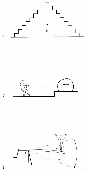
1Gravity force (compresses the pyramid)
2Pulling force (moves the boulder)
3Moment = force times lever arm (M = P L)
A Point about which the force rotates
LLever arm
MMoment
PForce
4-2 MECHANICS Statics
Static Equilibrium
For any body to be in static equilibrium, all forces and moments acting on it must be in equilibrium, i.e. their sum must equal zero. This powerful concept is used for static analysis and defined by the following three equation of statics:
ΣH = 0 (all horizontal forces must equal zero)
ΣV = 0 (all vertical forces must equal zero)
ΣM = 0 (all moments must equal zero)
The equilibrium equations are illustrated as follows:
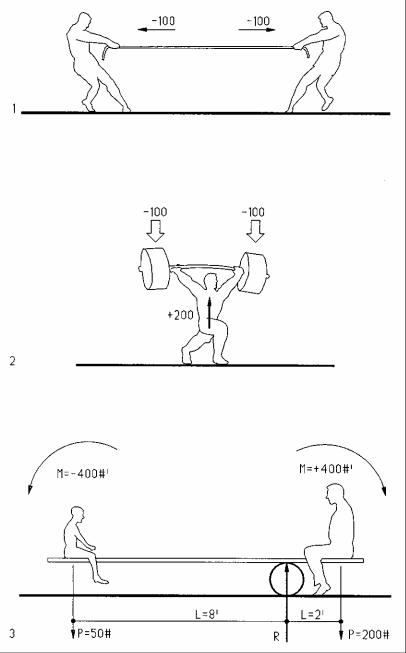
1Horizontal equilibrium: pulling left and right with equal forces, mathematically defined as
ΣH = 0 = + 100 – 100 = 0
2Vertical equilibrium: pushing up with a force equal to a weight, mathematically defined as:
ΣV = 0 = – 2 x 100 + 200 = 0
3Moment equilibrium: balancing both sides of a balance board, mathematically defined as:
ΣM = 0 = – 50# (8’) + 200# (2’) = - 400 + 400 = 0
Much of this book is based on the three equilibrium equations.
4-3 MECHANICS Statics
Supports
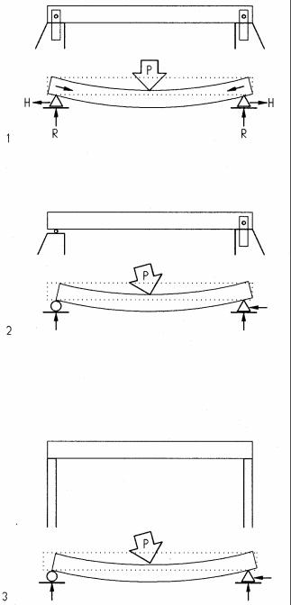
For convenience, support types are described for beams, but apply to other horizontal elements, like trusses, as well. The type of support affects analysis and design, as well as performance. Given the three equations of statics defined above, ΣH=0, ΣV=0, and ΣM=0, beams with three unknown reactions are considered determinate (as described below) and can be analyzed by the three static equations. Beams with more than three unknown reactions are considered indeterminate and cannot be analyzed by the three static equations alone. A beam with two pin supports (1 has four unknown reactions, one horizontal and one vertical reaction at each support. Under load, in addition to bending, this beam would deform like a suspended cable in tension, making the analysis more complex and not possible with static equations.
By contrast, a beam with one pin and one roller support (2) has only three unknown reactions, one horizontal and two vertical. In bridge structures such supports are quite common. To simplify analysis, in building structures this type of support may be assumed, since supporting walls or columns usually are flexible enough to simulate the same behavior as one pin and one roller support. The diagrams at left show for each support on top the physical conditions and below the symbolic abstraction.
1Beam with fixed supports at both ends subject to bending and tension
2Simple beam with one pin and one roller support subject to bending only
3Beam with flexible supports, behaves like a simple beam
Simple beams, supported by one pin and one roller, are very common and easy to analyze. Designations of rollerand pin supports are used to describe the structural behavior assumed for analysis, but do not always reflect the actual physical support. For example, a pin support is not an actual pin but a support that resists horizontal and vertical movement but allows rotation. Roller supports may consist of Teflon or similar material of low friction that allows horizontal movement like a roller.
4-4 MECHANICS Statics
Support symbols
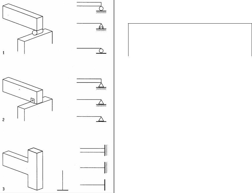
The diagrams show common types of support at left and related symbols at right. In addition to the pin and roller support described above, they also include fixed-end support (as used in steel and concrete moment frames, for example).
Support types
|
|
|
Degrees of freedom |
|
|
|
Support type |
Horizontal |
|
Vertical |
Rotation |
|
|
movement |
|
movement |
|
1 |
Roller |
Free |
|
Fixed |
Free |
2 |
Pin |
Fixed |
|
Fixed |
Free |
3 |
Rigid |
Fixed |
|
Fixed |
Fixed |
4-5 MECHANICS Statics
a b
Ra Rb
Reactions
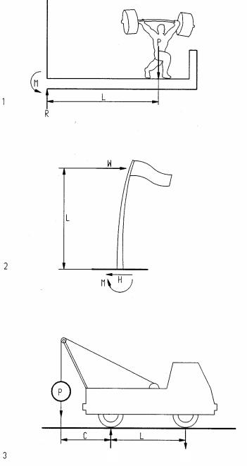
Support reactions for asymmetrical loads and/or supports are computed using the equations of statics, ΣH=0, ΣV=0, and ΣM=0. The following examples illustrate the use of the three equations to find reactions.
1Weight lifter on balcony
Assume:
P = 400#, L = 6’
Σ V = 0 ↑ + |
|
R – P = 0 |
|
R = P |
R = 400 # |
Σ M = 0, + |
|
P L – M = 0 |
|
M = P L = 400 x 6 |
M =2,400 #’ |
2.Flag pole
Assume:
H = 80# (wind load on flag) L = 20’
Σ H = 0 → + |
|
W – H = 0 |
|
H = W |
H = 80 # |
Σ M = 0 + |
|
W L + M = 0 |
|
M = - W L = - 80 x 20 |
M = -1,600 #’ |
Note: |
|
The negative moment implies, the positive moment arrow must be reversed
3 |
Tow truck |
|
|
|
Assume: |
|
|
|
P = 2k, C = 7’, |
L = 10’ |
|
|
Σ Ma = 0 + |
|
|
|
Rb L - P C = 0 |
|
|
|
Rb = P C / L = 2 x 7 / 10 |
Rb = 1.4k |
|
|
Σ Mb = 0 + |
|
|
|
Ra L - P (C+L) = 0 |
|
|
|
Ra = P (C+L) /L = 2 (7+10) / 10 |
Ra = +3.4k |
|
|
Check Σ V = 0 |
|
|
|
Σ V = 0 = +3.4 –1.4 –2 |
ΣV = 0 |
|
|
Note: |
|
|
|
The lever arm is always perpendicular to load |
|
|
|
Rb pointing downward is provided by the truck weight |
|
|
4-6 |
MECHANICS |
Statics |
|
W=960
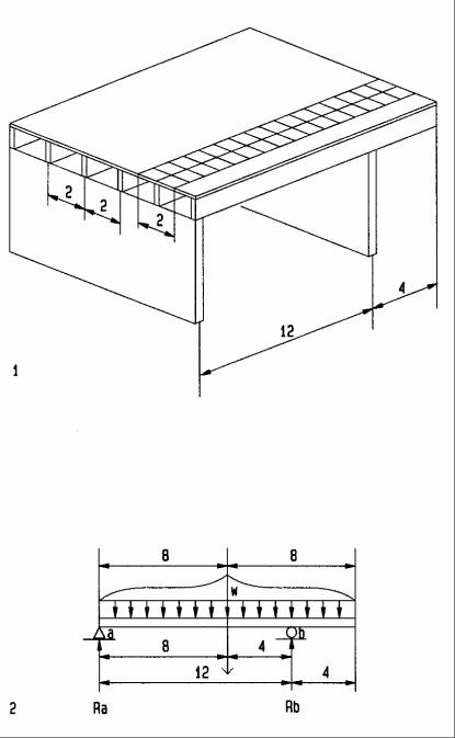
Beam reactions
To find reactions for asymmetrical beams:
•Draw an abstract beam diagram to illustrate computations
•Use Σ M = 0 at one support to find reaction at other support
•Verify results for vertical equilibrium
1Floor framing
2Abstract beam diagram Assume:
DL = 10 psf LL = 20 psf
Σ = 30 psf
Uniform beam load: |
|
w = 30 psf x 2’ |
w = 60 plf |
For convenience, substitute total beam load W for uniform load w at its centroid |
|
Total beam load |
|
W = w L = 60 (12+4) |
W = 960 # |
Support reactions: |
|
Σ M b = 0 + |
|
12 Ra – 4 W = 0 |
|
Ra = 4 x 960 / 12 |
Ra = 320 # |
Σ Ma = 0 + |
|
8 W – 12 Rb= 0 |
|
12 Rb = 8 x 960 |
|
Rb = 8 x 960 / 12 |
Rb = 640 # |
Check Σ V = 0 ↑+ |
|
Ra + Rb – W= 320 + 640 – 960 = 0 |
Σ V = 0 |
Alternate method (use uniform load directly) |
|
Support reactions: |
|
Σ M b = 0 + |
|
12 Ra – 4 x 60 plf x 16’ = 0 |
|
Ra = 4 x 60 x 16 / 12 |
Ra = 320 # |
Σ M a = 0 + |
|
8 x 60 x 16 – 12 Rb= 0 |
|
12 Rb = 8 x 60 x 16 |
|
Rb = 8 x 60 x 16 / 12 |
Rb = 640 # |
Check Σ V = 0 ↑+ |
|
Ra + Rb – W= 320 + 640 – 960 = 0 |
Σ V = 0 |
4-7 MECHANICS Statics
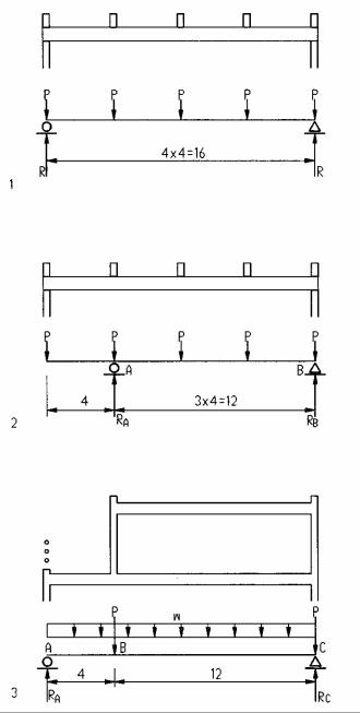
1 |
Simple beam with point loads |
|
|
Assume: P = 1.2k |
|
|
R = 5 P / 2 = 5 x 1.2 / 2 |
R = 3 k |
2Beam with overhang and point loads
Assume: P = 2k
|
|
|
Σ M b = 0 + |
|
|
|
|||
|
|
|
12 Ra - 2x16 - 2x12 - 2x8 - 2x4 = 0 |
|
|
|
|
Ra = (32 + 24 + 16 + 8) / 12 |
Ra = 6.67 k |
|
||||
|
|
|
Σ Ma = 0 + |
|
|
|
|
-12 Rb - 2x4 + 2x4 + 2x8 + 2x12 = 0 |
|
|
|
|
Rb = (2 x 8 + 2 x 12) / 12 |
Rb = 3.33 k |
|
|
|
Check Σ V = 0 ↑+ |
|
|
|
|
6.67 + 3.33 – 5 x 2 |
Σ V = 0 |
3Beam with uniform load and point load (wall) Assume: w = 100 plf, P = 800#
Σ M c = 0 + |
|
|
16 Ra – 100x16x8 – 800x12 = 0 |
Ra = 1,400 |
# |
Ra = (100x16x8 + 800x12) / 16 |
||
Σ Ma = 0 + |
|
|
-16 Rc + 100x16x8 + 800 x 4 +800 x16 = 0 |
|
|
Rc = (100x16x8 + 800x4 +800 x16) / 16 |
Rc = 1800 |
# |
Check Σ V = 0 ↑ + |
|
|
1400+1800-100x16-800-800 |
Σ V = 0 |
|
4-8 MECHANICS Statics
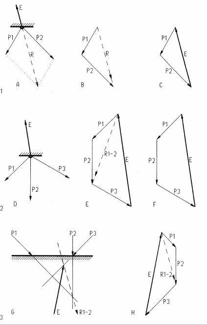
Vector Analysis
First used by Leonardo da Vinci, graphic vector analysis is a powerful method to analyze and visualize the flow of forces through a structure. However, the use of this method is restricted to statically determinate systems. In addition to forces, vectors may represent displacement, velocity, etc. Though only two-dimensional forces are described here, vectors may represent forces in three-dimensional space as well. Vectors are defined by magnitude, line of action, and direction, represented by a straight line with an arrow and defined as follows:
Magnitude is the vector length in a force scale, like 1” =10 k or 1 cm=50 kN Line of Action is the vector slope and location in space
Direction is defined by an arrow pointing in the direction of action
1Two force vectors P1 and P2 acting on a body pull in a certain direction. The resultant R is a force with the same results as P1 and P2 combined, pulling in the same general direction. The resultant is found by drawing a force parallelogram [A] or a force triangle [B]. Lines in the vector triangle must be parallel to corresponding lines in the vector plan [A]. The line of action of the resultant is at the intersection of P1 / P2 in the vector plan [A]. Since most structures must be at rest it is more useful to find the equilibriant E that puts a set of forces in equilibrium [C]. The equilibriant is equal in magnitude but opposite in direction to the resultant. The equilibriant closes a force triangle with all vectors connected head-to-tail. The line of action of the equilibriant is also at the intersection of P1/P2 in the vector plan [A].
2The equilibriant of three forces [D] is found, combining interim resultant R1-2 of forces P1 and P2 with P3 [E]. This process may be repeated for any number of forces. The interim resultants help to clarify the process but are not required [F]. The line of action of the equilibriant is located at the intersection of all forces in the vector plan [D]. Finding the equilibriant for any number of forces may be stated as follows:
The equilibriant closes a force polygon with all forces connected head-to-tail, and puts them in equilibrium in the force plan.
3The equilibriant of forces without a common cross-point [G] is found in stages: First the interim resultant R1-2 of P1 and P2 is found [H] and located at the intersection of P1/P2 in the vector plan [G]. P3 is then combined with R1-2 to find the equilibriant for all three forces, located at the intersection of R1-2 with P3 in the vector plan. The process is repeated for any number of forces.
4-13 MECHANICS Statics