

- •VOLUME 5
- •CONTRIBUTOR LIST
- •PREFACE
- •LIST OF ARTICLES
- •ABBREVIATIONS AND ACRONYMS
- •CONVERSION FACTORS AND UNIT SYMBOLS
- •NANOPARTICLES
- •NEONATAL MONITORING
- •NERVE CONDUCTION STUDIES.
- •NEUROLOGICAL MONITORS
- •NEUROMUSCULAR STIMULATION.
- •NEUTRON ACTIVATION ANALYSIS
- •NEUTRON BEAM THERAPY
- •NEUROSTIMULATION.
- •NONIONIZING RADIATION, BIOLOGICAL EFFECTS OF
- •NUCLEAR MAGNETIC RESONANCE SPECTROSCOPY
- •NUCLEAR MEDICINE INSTRUMENTATION
- •NUCLEAR MEDICINE, COMPUTERS IN
- •NUTRITION, PARENTERAL
- •NYSTAGMOGRAPHY.
- •OCULAR FUNDUS REFLECTOMETRY
- •OCULAR MOTILITY RECORDING AND NYSTAGMUS
- •OCULOGRAPHY.
- •OFFICE AUTOMATION SYSTEMS
- •OPTICAL FIBERS IN MEDICINE.
- •OPTICAL SENSORS
- •OPTICAL TWEEZERS
- •ORAL CONTRACEPTIVES.
- •ORTHOPEDIC DEVICES MATERIALS AND DESIGN OF
- •ORTHOPEDICS PROSTHESIS FIXATION FOR
- •ORTHOTICS.
- •OSTEOPOROSIS.
- •OVULATION, DETECTION OF.
- •OXYGEN ANALYZERS
- •OXYGEN SENSORS
- •OXYGEN TOXICITY.
- •PACEMAKERS
- •PAIN SYNDROMES.
- •PANCREAS, ARTIFICIAL
- •PARENTERAL NUTRITION.
- •PERINATAL MONITORING.
- •PERIPHERAL VASCULAR NONINVASIVE MEASUREMENTS
- •PET SCAN.
- •PHANTOM MATERIALS IN RADIOLOGY
- •PHARMACOKINETICS AND PHARMACODYNAMICS
- •PHONOCARDIOGRAPHY
- •PHOTOTHERAPY.
- •PHOTOGRAPHY, MEDICAL
- •PHYSIOLOGICAL SYSTEMS MODELING
- •PICTURE ARCHIVING AND COMMUNICATION SYSTEMS
- •PIEZOELECTRIC SENSORS
- •PLETHYSMOGRAPHY.
- •PNEUMATIC ANTISHOCK GARMENT.
- •PNEUMOTACHOMETERS
- •POLYMERASE CHAIN REACTION
- •POLYMERIC MATERIALS
- •POLYMERS.
- •PRODUCT LIABILITY.
- •PROSTHESES, VISUAL.
- •PROSTHESIS FIXATION, ORTHOPEDIC.
- •POROUS MATERIALS FOR BIOLOGICAL APPLICATIONS
- •POSITRON EMISSION TOMOGRAPHY
- •PROSTATE SEED IMPLANTS
- •PTCA.
- •PULMONARY MECHANICS.
- •PULMONARY PHYSIOLOGY
- •PUMPS, INFUSION.
- •QUALITY CONTROL, X-RAY.
- •QUALITY-OF-LIFE MEASURES, CLINICAL SIGNIFICANCE OF
- •RADIATION DETECTORS.
- •RADIATION DOSIMETRY FOR ONCOLOGY
- •RADIATION DOSIMETRY, THREE-DIMENSIONAL
- •RADIATION, EFFECTS OF.
- •RADIATION PROTECTION INSTRUMENTATION
- •RADIATION THERAPY, INTENSITY MODULATED
- •RADIATION THERAPY SIMULATOR
- •RADIATION THERAPY TREATMENT PLANNING, MONTE CARLO CALCULATIONS IN
- •RADIATION THERAPY, QUALITY ASSURANCE IN
- •RADIATION, ULTRAVIOLET.
- •RADIOACTIVE DECAY.
- •RADIOACTIVE SEED IMPLANTATION.
- •RADIOIMMUNODETECTION.
- •RADIOISOTOPE IMAGING EQUIPMENT.
- •RADIOLOGY INFORMATION SYSTEMS
- •RADIOLOGY, PHANTOM MATERIALS.
- •RADIOMETRY.
- •RADIONUCLIDE PRODUCTION AND RADIOACTIVE DECAY
- •RADIOPHARMACEUTICAL DOSIMETRY
- •RADIOSURGERY, STEREOTACTIC
- •RADIOTHERAPY ACCESSORIES
an IMRT moniker by the vendor, but this product does not meet the NCI–CWG–IMRT definition of IMRT. Research interest in the subject continues to grow. A literature search of ‘‘inverse treatment planning’’ found 39 publications in 1998, 48 in 2000, and 108 in 2002, so we can expect optimization algorithms to continue to be tested and improved.
The rapid acceptance of IMRT as a delivery technique is unprecedented in radiation therapy. A mere 6 years after Brahme postulated the concept in 1988, Carol had produced a commercial system that was used clinically. Within a decade after that event, not only do vendors supply additional technology for their accelerators to treat IMRT, but also a new vendor has emerged with a dramatically new machine to treat only IMRT. Image guided systems are being adapted to take advantage of the power to shape radiation fields easily and precisely with IMRT. This technology should continue to expand.
BIBLIOGRAPHY
1.NCI–CWG–IMRT, Intensity-modulated radiotherapy: Current status and issues of interest. Int J Radiat Oncol Biol Phys 2001;51:880–914.
2.Brahme A, Roos JE, Lax I. Solution of an integral equation encountered in rotation therapy. Phys Med Biol 1982;27: 1221–1229.
3.Cormack AM, Cormack RA. A problem in rotation therapy with x-rays: Dose distributions with an axis of symmetry. Int J Radiat Oncol Biol Phys 1987;13:1921–1925.
4.Brahme A. Optimization of stationary and moving beam radiation therapy techniques. Radiother Oncol 1988;12:129–140.
5.Powers WE et al. A new system of field shaping for externalbeam radiation therapy. Radiology 1973;108:407–411.
6.Sofia JW. Computer controlled, multileaf collimator for rotational radiation therapy. AJR Am J Roentgenol 1979;133: 956–957.
7.Boyer A et al. Basic applications of multileaf collimator; AAPM Report No. 72. Madison (WI): Medical Physics Publishing; 2001.
8.Bortfeld T, Burkelbach J, Boesecke R, Schlegel W. Methods of image reconstruction from projections applied to conformation radiotherapy. Phys Med Biol 1990;35:1423–1434.
9.Webb S. Optimization by simulated annealing of three-dimen- sional conformal treatment planning for radiation fields defined by a multileaf collimator. Phys Med Biol 1991;36: 1201– 1226.
10.Bortfeld T et al. Realization and verification of three-dimen- sional conformal radiotherapy with modulated fields. Int J Radiat Oncol Biol Phys 1994;30:899–908.
11.Kallman P, Lind B, Eklof A, Brahme A. Shaping of arbitrary dose distributions by dynamic multileaf collimation. Phys Med Biol 1988;33:1291–1300.
12.Stein J, Bortfeld T, Dorschel B, Schlegel W. Dynamic x-ray compensation for conformal radiotherapy by means of multi-leaf collimation. Radiother Oncol 1994;32:163–173.
13.Svensson R, Kallman P, Brahme A. An analytical solution for the dynamic control of multileaf collimators. Phys Med Biol 1994;39:37–61.
14.Spirou SV, Chui CS. Generation of arbitrary intensity profiles by dynamic jaws or multileaf collimators. Med Phys 1994;21: 1031–1041.
15.Carol MP. Integrated 3-D conformal multivane intensity modulation delivery system for radiotherapy. Hounsell AR, Wilkinson JM, Williams PC, editors. Proceedings of the 11th International Conference on the Use of Computers in Radiation Therapy. Madison (WI): Medical Physics Publishing; 1994.
RADIATION THERAPY SIMULATOR |
525 |
16.Butler EB, Woo SY, Grant 3rd W, Nizin PS. Clinical realization of 3d conformal intensity modulated radiotherapy. Int J Radiat Oncol Biol Phys 1995;32:1547–1548.
17.Yu CX. Intensity-modulated arc therapy with dynamic multileaf collimation: An alternative to tomotherapy. Phys Med Biol 1995;40:1435–1449.
18.Yu C, Shepard D. Treatment planning for stereotactic radiosurgery with photon beams. Technol Cancer Res Treat 2003;2:93–104.
19.Mackie TR, et al. Tomotherapy: A new concept for the delivery of dynamic conformal radiotherapy. Med Phys 1993;20:1709–1719.
20.Webb S. Optimisation of conformal radiotherapy dose distributions by simulated annealing. Phys Med Biol 1989;34: 1349–1370.
21.Mohan R, et al. Clinically relevant optimization of 3-d conformal treatments. Med Phys 1992;19:933–944.
See also COMPUTED TOMOGRAPHY; RADIOTHERAPY, THREE-DIMENSIONAL CONFORMAL.
RADIATION THERAPY SIMULATOR
DANIEL A. LOW
SASA MUTIC
Washington University School of
Medicine
St. Louis, Missouri
INTRODUCTION
Radiation therapy, or radiation oncology, is one of the primary modalities (along with surgery and chemotherapy) for the treatment of cancer patients. Its origins can be traced to the early 1900s and today radiation therapy facilities can be found in most major medical centers and many free standing practices. This medical specialty and its success depend strongly on the technology used for cancer diagnosis and planning, delivery, and verification of patient treatments. Therefore, the amount of efforts and resources invested in the improvement of radiation therapy related technologies is significant. One of the cornerstones of modern radiation therapy practices are volumetric patient images, computed tomography (CT), magnetic resonance (MR) imaging, nuclear medicine imaging (positron emission tomography (PET) and single positron emission tomography (SPECT)), and ultrasound (US). Medical images are used for cancer detection, disease staging, treatment planning, for verification of treatment delivery, and for evaluation of treatment outcomes and patient follow up. Imaging devices that are used to image cancer patients for radiation therapy treatment planning are called Radiation Therapy Simulators. The distinguishing characteristics of radiation therapy simulators, in addition to their basic imaging properties, are that these devices need to have the following characteristics; (1) the modality allows patients to be imaged in their treatment position, (2) that the acquired images have high spatial accuracy, and (3) that the dataset be able to provide image datasets that are of sufficient quality to be used for validating the radiation beam shape and anatomic location. While these may seem like relatively straightforward
526 RADIATION THERAPY SIMULATOR
requirements, the design and implementation of radiation therapy simulators can be technically challenging. The main source of technical difficulties stems from the fact that the design of the medical imaging devices on which the simulators are based has historically been driven by the needs of diagnostic radiology that have less concern for patient positioning or for the spatial accuracy of the image datasets. For diagnostic scanning, patients often assume a comfortable position with their arms on the side or on abdomen–chest. Diagnostic physicians typically need to determine the presence of anatomic or functional anomalies, so a quantified determination of the size, shape, or location of internal organs or tumors relative to the imaging modality hardware is not a primary consideration.
For radiation therapy imaging, the patient extremities (arms and legs) are often positioned away from the torso to provide access by the radiation treatment beams. Patients are also imaged in immobilization devices that are subsequently used during treatment. Additionally, image spatial accuracy and the geometry of images is extremely important in order to precisely deliver the radiation to the tumors while avoiding radiation sensitive organs. Radiation therapy simulator design is based on an imaging device that was originally developed for diagnostic imaging, and then the device is modified to accommodate patient imaging in the radiotherapy treatment position and to improve image spatial accuracy and geometry to satisfy the needs of radiation therapy treatment planning. This approach is slowly changing and more devices are being designed exclusively for radiation therapy or major features of diagnostic imaging equipment are designed with radiation therapy in mind. This change in manufacturer attitude is reflected in description of radiation therapy simulators in the rest of this article.
The majority of simulation history in radiation therapy is based on conventional simulators (1–6). However, the modern practice of radiation therapy is dominated by CT simulators. Shortly after the introduction of clinical
CT scanners in the early 1970s, it was realized that this imaging modality has much to offer in a radiation oncology setting. The CT images provide volumetric information not only about target volumes, but about critical structures as well. Using CT images for radiation therapy treatment, planning has improved dose delivery to target volumes while reducing dose to critical organs. The CT images also provide relative electron density information for hetero- geneity-based dose calculations. A major weakness of CT imaging is a relatively limited soft-tissue contrast. This limitation can be overcome by using CT images in conjunction with MR studies for treatment planning. The PET images can be used to add physiological information. Ultrasound has also been useful for imaging in brachytherapy. Multimodality imaging-based treatment planning and target and normal structure delineation offer an opportunity to better define the anatomic extent of target volumes and to define their biologic properties.
Tatcher (7) proposed treatment simulation with CT scanners. This short article described the feasibility of CT simulator and indicated potential economical benefits. In 1983, Goitein and Abrams (8,9) further described multidimensional treatment planning based on CT images. Sherouse et al. (10,11) went on to describe a CT image based virtual simulation process that they referred to as a ‘‘software analog to a conventional simulation’’. This series of manuscripts described software tools and addressed technical issues that affect today’s CT-simulation process. The manuscripts pointed out the need for fast computers, specialized software, but also for improved patient immobilization and setup reproducibility.
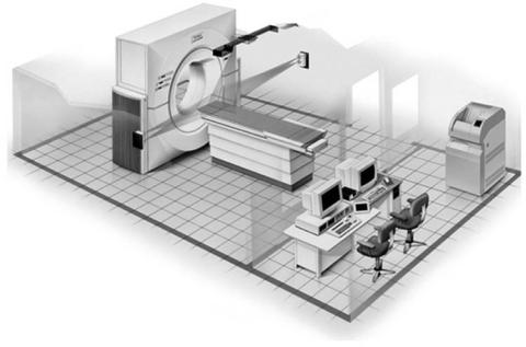
The radiation oncology community eagerly embraced the concept of virtual simulation and in early 1990s commercial software packages became available. These systems consisted of a diagnostic CT scanner, external laser positioning system, and a virtual simulation software work station. One of the early commercial CT simulation packages is shown in Fig. 1.
Figure 1. The CT-simulator room layout. (Image courtesy of Philips Medical Systems, Cleveland, Ohio.)

RADIATION THERAPY SIMULATOR |
527 |
CT simulator
CT Scanner |
Virtual |
Dose |
|
simulation |
calculation |
|
|
|
|
||
|
|
|
Figure 2. Place of CT simulation in radio- |
|
Treatment planning system |
therapy treatment planning process. (Reprinted |
|
|
with permission from Ref. 12.) |
||
The CT simulators have matured to a point where they are one of the cornerstones of modern radiation oncology facilities. Today’s systems incorporate specially designed large bore CT scanners, multislice CT scanners, high quality laser positioning systems, and sophisticated virtual simulation packages. Many systems incorporate dose calculation capabilities and treatment plan analysis and evaluation tools.
Additional virtual simulation software features and functions along with increased efficiency and flexibility have enabled CT simulators to replace conventional simulators in many facilities. This trend seems to be further fueled by the increased demand for imaging studies for conformal three-dimensional (3D) and intensity modulated radiation therapy (IMRT) treatment planning where conventional simulators are of limited value. Figure 2 shows the place of CT simulation in the treatment planning process.
Both MR and PET–CT simulators are recent developments in radiation therapy simulation and are designed to complement CT simulation process and shortcomings of CT imaging. Magnetic resonance imaging offers superior soft tissue contrast and PET provides information about biological tissue properties. Computed tomography has relatively poor soft tissue contrast and provides rather limited information about functional tissue characteristics. Both MR and PET imaging in radiation therapy imaging greatly enhance our ability to accurately define anatomical and biological properties of tumors and normal tissues.
The implementation of simulation and treatment planning process varies greatly between radiation oncology departments. This diversity is in part driven by significant technical differences between simulation and treatment planning systems offered by different manufacturers. The discussion of radiotherapy simulators provided here describes general characteristic of processes and technology used for radiation therapy treatment planning. For more specific details, readers are referred to suggested readings list.
TECHNOLOGY OVERVIEW
In the late 1990s, the imaging equipment manufacturers began designing major devices (CT, MR, and PET scanners) specifically for radiation therapy or with radiation therapy needs in mind. This paradigm change resulted in a multitude of imaging devices available for radiation
therapy simulation. Not only are there new devices (CT, MR, PET), but conventional simulators are being improved as well in order to be able to compete with other imaging modalities.
CONVENTIONAL SIMULATOR
The radiation therapy simulator has been an integral component of the treatment planning process for > 30 years. Conventional simulators are a combination of diagnostic X-ray machine and certain components of a radiation therapy linear accelerator (1–6). A conventional simulator, as seen in Fig. 3, consists of a diagnostic X-ray unit and fluoroscopic imaging system (X-ray tube, filters, collimation, image intensifier, video camera, generator, etc. (13), patient support assembly (a model of the treatment table), laser patient positioning and marking system, and simulation and connectivity software. The treatment table and the gantry are designed to mimic the geometric functions of a linear accelerator. The gantry head is designed to accommodate the common beam modification devices (blocks, wedges, compensating filters), in a geometry that mimics the linear accelerator. The simulator provides transmission radiographs with radiation portaldefining collimator settings outlined by delineator wires. By using primarily bony landmarks, the physician delineates the radiation portal outlines.
Imaging chain: One of the major improvements in conventional simulator design was the replacement of image intensifiers and video camera systems by amorphous silicon detectors. The new imagers produce high spatial and contrast resolution images which approach film quality, Fig. 4. More importantly, these images are distortion-free, a feature that is important for accurate geometric representation of patient anatomy. The introduction of high quality digital imagers in conventional simulation further facilitates the concept of film-less radiation oncology departments.
Simulation software: Conventional simulation software has also undergone many improvements. Modern simulators use the Digital Image Communications in Medicine (DICOM) standard (14) for data import capabilities. Treatment field parameters can be imported directly from the treatment planning computer for verification on the simulator. The software can then automatically set the simulator parameters according to the treatment plan. This facilitates efficient and accurate verification of patient
528 RADIATION THERAPY SIMULATOR
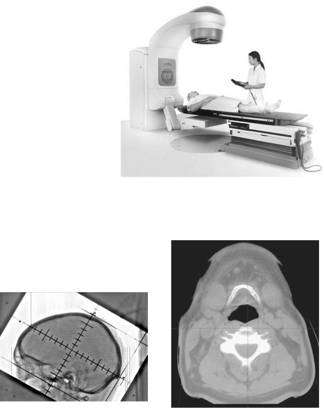
Figure 3. Modern version of a conventional simulator. (Image courtesy of Varian Medical Systems, Palo Alto, California, copyright #2002.)
treatment setup on the conventional simulator. These simulators also have DICOM export capabilities that improves the reliability of treatment setup parameter transfer directly to a record and verify system or to a treatment planning computer. The ability to import and capture digital images enables conventional simulators to have tools for automatic correlation of treatment planning and verification fields.
Another potential improvement for conventional simulators is the capability of providing cone-beam CT (15,16). Because newer simulators are equipped with digital imaging hardware, two-dimensional (2D) projection image datasets
are acquired while the gantry is rotating. The projection data is used to reconstruct a high spatial resolution CT image dataset. This capability will significantly improve imaging capabilities and usefulness of these devices. Figure 5 shows a cone beam CT image from a conventional simulator.
Figure 4. Digital image of a head from a modern conventional simulator equipped with an amorphous silicon imager. (Image courtesy of Varian Medical Systems, Palo Alto, California, copyright # 2002.)
Figure 5. ConebeamCT image of a headacquiredona conventional simulator. (Image courtesy of Varian Medical Systems, Palo Alto, California, copyright # 2002.)
While it is often mentioned that conventional simulators can be completely replaced with CT simulators, new features and usefulness of conventional simulators are slowing down this process. Conventional simulator continues to be an important component of radiotherapy process even though its use for treatment planning of many tumor sites has been significantly reduced.
CT Simulator
Computed tomography simulator (10,11,17–26) consists of a CT scanner, laser patient positioning–marking system, virtual simulation–3D treatment planning software, and different hardcopy output devices, Fig. 1.
The CT scanner is used to acquire volumetric CT scan of a patient that represents the virtual patient and the simulation software recreates the functions of a conventional simulator. In recent years, the three most significant changes in CT-simulation technology have been the introduction of a larger gantry bore opening (Large Bore CT) (27), multislice image acquisition (Multislice CT) (28), and addition of CT-simulation software directly on the CT scanner control console. These innovations improve the efficiency and accuracy of the CT-simulation process. They also improve the patient experience by allowing patients to be positioned in more comfortable positions while reducing the simulation procedure time.
Large Bore CT: Large bore CT scanners (defined here as having > 70 cm diameter bores) were specifically designed with radiation therapy needs in mind. One of the requirements in treatment of several cancer sites (breast, lung, vulva, etc.) is for extremities to be positioned away from the torso. When acquiring a CT scan with a patient in such treatment position, extremities often cannot fit through a conventional 70 cm diameter scanner bore opening. In such situations, patient positioning needs to be modified to acquire the scan. This can result in less than optimal treatment position (patient may be less comfortable and therefore the daily setup reproducibility may be compromised) or in a mismatch between the imaging and treatment positions. The first large bore CT simulator was introduced in 2000, and several additional models with enlarged bore opening have been introduced since then.
Large bore scanners also have increased the available scan field of view (SFOV), which determines the largest dimension of an object that can be fully included in the CT image. It is typically 48–50 cm in diameter on most conventional 70 cm bore opening scanners. For treatment planning purposes it is necessary to have the full extent of the patient’s skin on the CT image. Lateral patient separation can often be > 48–50 cm and the skin is then not visible on CT images. Increased SFOV available on large bore scanners solves this problem. There are, however, differences in implementation of extended SFOV and validity of quantitative CT values (quantitative CT) at larger image sizes. The CT numbers for some scanners are accurate only for smaller SFOVs and the values toward the periphery of large SFOV images are not reliable. This can be a concern for some dose calculation algorithms because inaccurate CT numbers can lead to dose calculation errors. The impact of CT number accuracy for increased SFOV
RADIATION THERAPY SIMULATOR |
529 |
images on dose calculation accuracy should be evaluated during scanner commissioning.
Multislice CT: In 1992, Elscint introduced a scanner that had a dual row of detectors and could simultaneously acquire two images (slices). Since then, multislice CT has gained wide spread acceptance and scanners that can acquire up to 64 slices are now available from all major vendors. The basic design behind the multislice CT technology is that multiple rows of detectors are used to create several images for one rotation of the X-ray tube around the patient.
One of the obstacles for radiation therapy scanning with single-slice scanners is the limited tube heat loading capability. Often, fewer images are taken, slice thickness is increased, the image quality is decreased (reduced mAs), or scan pitch is increased to reduce the amount of heat produced during the scan and to allow for the entire scan to be acquired in a single acquisition. Due to the longer length of imaged volume per tube rotation (multiple slices acquired simultaneously), the tube heat loading for a particular patient volume is reduced when using a multislice scanner relative to a single-slice scanner and multislice scanners are generally not associated with tube heat loading concerns. Faster acquisition times and decreased tube loading of multislice scanners, which allow longer volumes to be scanned in a single acquisition, can provide an advantage over single-slice systems for treatment planning purposes. Multislice technology can be especially beneficial for imaging of the thorax where breathing artifacts can be minimized with faster scanning. Multislice technology also facilitates dynamic CT scanning, often referred to as 4D CT (29,30). This application of multislice CT in radiation therapy is yet to be fully explored.
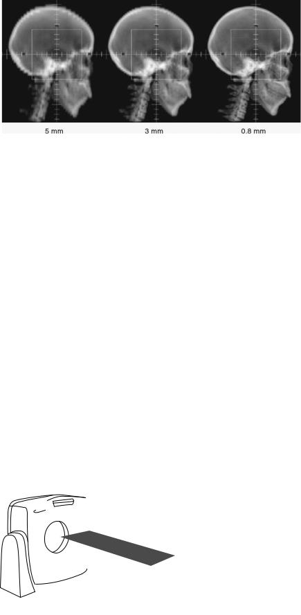
Multislice scanners are also capable of acquiring thinner slices that can result in better quality digitally reconstructed radiographs, used for treatment portal validation, and more accurate target delineation because of the improved spatial resolution with thinner slices, (Fig. 6).
CT simulator tabletop: This section and discussion about simulator tabletops applies equally to all simulators used in radiation therapy (conventional, MRI, CT, and PET) and treatment machines. Tabletops used for patient support in radiation therapy during imaging or treatment should facilitate easy, efficient, reproducible, and accurate patient. It is not only important that a tabletop improves patient positioning on a single device (i.e., treatment machine), but the repositioning of a patient from one imaging or treatment device to another also has to be considered. A great improvement in this process is if all tabletops involved in patient simulation and treatment have a common design. They do not have to be identical, but they should have the same dimensions (primarily width), flex and sag under patient weight, and they should allow registration (indexing) of patient immobilization devices to the tabletop. Figure 7 demonstrates this concept. The CT simulator tabletop has the same width as the linear accelerator used for patient treatment and both allow registration of patient immobilization system to the treatment couch. The ability to register the immobilization device and the patient to a treatment table is extremely important and improves immobilization, set-up
530 RADIATION THERAPY SIMULATOR
Figure 6. The CT slice thickness DRRs are 5, 3, and 0.8 mm. Thinner slice thickness images reveal much more relevant anatomical detail.
reproducibility, accuracy, and efficiency. The patient is always positioned in the same place on the treatment machine and patient daily setup can be facilitated using the treatment couch positions. If the patient is registered to the treatment couch, the coordinates of the couch used for patient treatment can become a part of parameters that are set and tracked in the linear accelerator record and verify system.
Patient marking lasers: A laser system is necessary to provide reference marks on patient skin or on the immobilization device. Figure 1 shows a laser system for a CT simulator:
Wall lasers: Vertical and horizontal, mounted to the side of the gantry. These lasers can be fixed or movable.
Sagittal laser: Ceiling or wall mounted single laser, preferably movable. Scanner couch can move up/down and in/out, but cannot move left/right, therefore the sagittal laser should move left–right to allow marking away from patient mid line.
Scanner lasers: Internally mounted, vertical and horizontal lasers on either side of the gantry and an overhead sagittal laser.
MR Simulator
The MR images for radiotherapy treatment planning are usually acquired in diagnostic radiology departments
because few radiation oncology departments have a dedicated MR scanner. Furthermore, currently the majority of radiotherapy MR studies are limited to brain imaging. The MR scanner has a superior soft tissue contrast compared to CT imaging and there are several benefits that MR can offer for target delineation based on this advantage. There have been several reports describing use of MR scanners for imaging and treatment simulation in radiotherapy (31–35). Some of these reports have suggested that MR studies can be used without a corresponding CT scan for radiotherapy treatment planning. Indeed, if spatial distortions (the geometry of imaged objects is not always reproduced correctly), which is the largest concern with MR imaging, can be removed or minimized MR studies can be used as the primary imaging modality for several treatment sites. Superior soft tissue contrast provided by MR can also be an advantage for treatment planning of certain extracranial tumor sites like prostate, for example (36,37).
Conventional MR scanners are not well suited for extracranial imaging for treatment planning. The main difficulty is placement of patient in treatment position with immobilization device in the scanner. The small diameter and long length of conventional MR scanner openings significantly limits patient positioning options for imaging. Open MR scanners do not share these difficulties and patients can be scanned in conventional
Figure 7. Similarity in design of simulator and treatment machine tabletops allows efficient and accurate reproducibility of patient positioning. (Image courtesy of MED-TEC, Inc, Orange City, Iowa.)

RADIATION THERAPY SIMULATOR |
531 |
treatment positions. At least one manufacturer offers an open MR scanner that has been modified to serve as a radiotherapy simulator, Fig. 8. The scanner table is equipped with a flat top and external patient alignment lasers. The geometry of the scanner is then similar to the CT simulator. Another manufacturer offers a 70 cm diameter gantry opening conventional MRI scanner. The depth of the scanner opening is 125 cm. The dimensions of this scanner are very similar to a conventional CT scanner and in fact the scanner could be mistaken for a CT scanner. The ergonomics of this scanner are also well suited for radiotherapy simulation.
One of the major challenges with MR imaging for radiotherapy treatment planning are geometric distortions in acquired images. The MR scanners are often equipped with correction algorithms that will minimize geometrical distortions. These corrections do not affect the entire image and only the center portion of the image (center 20–35 cm diameter) is adequately correct (within 2 mm). Therefore, the representation of patient’s skin and peripheral anatomy for larger body sections may be inaccurate. The effect of these inaccuracies must be evaluated if dose distributions will be calculated directly on MR images.
PET–CT Simulator
The PET images for radiotherapy planning can come from a standalone PET scanner or a combined PET–CT unit. Combined PET–CT scanners are being installed in radiation oncology departments and are used for PET scanning, but also these machines can be used for CT scanning only without PET acquisition. Due to this purpose, these scanners can be classified as CT simulators, though PET–CT simulator term may be more appropriate. Combined PET– CT scanners offer several advantages for radiotherapy
Figure 8. A MR simulator. (Image courtesy of Philips Medical Systems, Cleveland, Ohio.)
imaging and are generally preferred over stand-alone units.
The first combined PET–CT prototype was introduced in 1998 at the University of Pittsburgh (38), since then all major manufacturers have produced several commercial models. The key description of PET–CT scanners is that a PET and a CT scanner are combined in the same housing. Meaning that there are two gantries (PET and CT) combined in one housing sharing a common couch. Image reconstruction and scanner operation is increasingly performed from one control console.
Combined PET–CT scanner design varies among different vendors with respect to PET detectors, image quality and resolution, speed, image field of view; number of CT slices, scanner couch design, gantry bore opening, and other considerations. Currently, the commercially available scanners have a 70 cm gantry opening for the CT portion, though large bore CT scanners will likely become part of PET–CT scanners in the future. The PET gantry opening ranges in diameter from 60 to 70 cm, meaning that some of the commercial scanners have a nonuniform gantry opening as the patient travels from the CT portion of the scanner to the PET side. More importantly, the scanners with the smaller gantry opening on the PET side will pose the same difficulties for radiotherapy scanning as stand-alone PET scanners. Again, the size of patient immobilization devices and patient scan–treatment position will have to be adapted to the size of the gantry opening.
The combined PET/CT technology offers two major benefits for radiotherapy planning. First, because the images are acquired on the same scanner, providing that the patient does not move between the two studies, the patient anatomy will have the same coordinates in both studies. These images have been registered using hardware rather than software registration. The second benefit of the
532 RADIATION THERAPY SIMULATOR
combined PET–CT units is that CT images are used to measure attenuation correction factors (ACFs) for the PET emission data, obviating the need for a time-consuming PET transmission scan (39,40). The use of CT images to generate PET ACFs reduces the scan time up to 40% and also provides essentially noiseless ACFs compared with those from standard PET transmission measurements (41). Shorter scan times can benefit radiotherapy patients who are scanned in treatment position that often can be uncomfortable and difficult to tolerate for prolonged amounts of time. One of the concerns with ACFs generated from CT images is mismatch or misalignment between CT and PET images due to respiration motion. The PET images are acquired during many cycles of free breathing and CT images are acquired as a snapshot in time at full inspiration, partial inspiration, or some form of shallow breathing. The breathing motion will cause mismatch in anatomy between PET and CT images in the base of lung and through the diaphragm region. This mismatch can result in artifacts in these areas that may influence diagnosis and radiotherapy target definition in this region. There are various gating methods that can be used during image acquisition to minimize the motion component and essentially acquire true, motionless, images of patient anatomy. Gated or 4D CT (with time being the fourth dimension) can be used to generate more reliable ACFs and also for radiotherapy treatment planning where gated delivery methods are being used.
Virtual Simulation Software
As with all software programs, user-friendly, fast, and well functioning virtual (CT) simulation software with useful features and tools will be a determining factor for success of a virtual simulation program. Commercially available programs far surpass in-house written software and are the most efficient approach to virtual simulation. Several features are very important when considering virtual simulation/3D treatment planning software:
Contouring and localization of structures: Contouring and localization of structures is often mentioned as one of the most time consuming tasks in the treatment planning process. The virtual simulation software should allow fast user-friendly contouring process with help of semiautomatic or automatic contouring tools. An array of editing tools (erase, rotate, translate, stretch, undo) should be available. An ability to add margins in three dimensions and to automatically draw treatment portals around target volumes should be available. An underlining emphasis should be functionality and efficiency.
Image processing and display: Virtual simulation workstation must be capable of processing large volumetric sets of images and displaying them in different views as quickly as possible (near real-time image manipulation and display is desired). The quality of reconstructed images is just as important as the quality of the original study set. The reconstructed images (DRRs and multiplanar reconstruction) are used for target volume definition and treatment verification and have a direct impact on accuracy of patient treatments.
Simulator geometry: A prerequisite of virtual simulation software is the ability to mimic functions of a conventional simulator and of a medical linear accelerator. The software has to be able to show gantry, couch, collimator, and jaw motion, SSD changes, beam divergence, and so on. The software should facilitate design of treatment portals with blocks and multileaf collimators.
DISCUSSION
As radiotherapy treatment planning and delivery technology and techniques change, so does the treatment simulation. The most significant change in the recent past has been the wide adoption of CT simulation to support conformal radiotherapy and 3D treatment planning. A CT simulation has gone from a concept practiced at few academic centers to several available sophisticated commercial systems located in hundreds of radiation oncology departments around the world. The concept has been embraced by the radiation community as a whole. The acceptance of virtual simulation comes from improved outcomes and increased efficiency associated with conformal radiation therapy. Image-based treatment planning is necessary to properly treat a multitude of cancers and CT simulation is a key component in this process. Due to demand for CT images, CT scanners are commonly found in radiation oncology departments. As CT technology and computer power continue to improve so will the simulation process, and it may no longer be based on CT alone. The PET–CT combined units are commercially available and could prove to be very useful for radiation oncology needs. Several authors have described MR simulators where the MR scanner has taken the place of the CT scanner. It is difficult to predict what will happen over the next 10 years, but it is safe to say that image based treatment planning will continue to evolve.
One great opportunity for an overall improvement of radiation oncology is the better understanding of tumors through biological imaging. Biological imaging has been shown to better characterize the extent of disease than anatomical imaging and also to better characterize individual tumor properties. Enhanced understanding of individual tumors can improve selection of the most appropriate therapy and better definition of target volumes. Improved target volumes can utilize the full potential of IMRT delivery. Biological imaging can also allow evaluation of tumor response and possibly modifications in therapy plan if the initial therapy is deemed not effective.
Future developments in radiotherapy treatment planning simulation process will involve the integration of biological imaging. It is likely that this process will be similar to the way that CT scanning was implemented in radiotherapy. The imaging equipment is initially located in diagnostic radiology facilities and as the demand increases the imaging is gradually moved directly to radiation oncology.
BIBLIOGRAPHY
1.Bomford CK, et al. Treatment Simulators. BJR 1989; (Suppl. 23).
2.Connors SG, Battista JJ, Bertin RJ., On the technical specifications of radiotherapy simulators. Med Phys 1984;11:341– 343.
3.Greene D, Nelson KA, Gibb R., The use of a linear accelerator ‘‘simulator’’ in radiotherapy. BJR 1964;37:394–397.
4.McCullough EC., Radiotherapy treatment simulators, in Advances in radiation oncology physics: dosimetry, treatment planning, and brachytherapy. In: Purdy JA, ed. Woodbury (NY): American Institute of Physics; 1992. pp 491–499.
5.McCullough EC, Earle JD., Selection, acceptance testing and quality control of radiotherapy simulators. Radiology 1979; 131:221–230.
6.Van Dyk J, Munro PN. Simulators. In: Van Dyk J, Editor. The modern technology in radiation oncology. Wisconsin Medical Physics Publishing; 1999. pp 95–129.
7.Tatcher M., Treatment simulators and computer assisted tomography. BJR 1977;50:294.
8.Goitein M, Abrams M. Multi-dimensional treatment planning: I. Delineation of anatomy. Int J Rad Oncol, Biol, Phys 1983;9(6): 777–787.
9.Goitein M, et al. Multi-dimensional treatment planning: II. Beam’s eye-view, back projection, and projection through CT sections. Inter J Rad Oncol, Biol, Phys 1983;9(6):789– 797.
10.Sherouse G, et al. Virtual Simulation: Concept and Implementation. In: Bruinvis IAD, et al. ed. Ninth Int Conf Use of Computers in Radiation Therapy. North-Holland Publishing Co.; 1987. pp 433–436.
11.Sherouse GW, Bourland JD, Reynolds K. Virtual simulation in the clinical setting: some practical considerations. Int J Radiat Oncol Biol Phys 1990;19:1059–1065.
12.Mutic S, et al. Quality assurance for CT simulators and the CT simulation process: Report of the AAPM Radiation Therapy Committee Task Group No. 66. Med Phys 2003;30: 2762–2792.
13.Bushberg JT, et al. Fluoroscopy, in The Essential Physics of Medical-Imaging. 2nd ed. Baltimore: Lippincott Williams & Wilkins; 2002.
14.(NEMA), N.E.M.A. Digital Imaging Communications in Medicine (DICOM). 1998.
15.Jaffray DA, et al. A radiographic and tomographic imaging system integrated into a medical linear accelerator for localization of bone and soft-tissue targets. Int J Rad Oncol, Biol, Phys 1999;45:773–789.
16.Jaffray DA, et al. Flat-panel cone-beam computed tomography for image-guided radiation therapy. Int J Rad Oncol, Biol, Phys 2002;53:1337–1349.
17.Kushima T, Kono M. New development of integrated CT simulation system for radiation therapy planning. Kobe J Med Sci 1993;39(5–6):197–213.
18.Nagata Y, et al. CT simulator: a new 3-D planning and simulating system for radiotherapy: Part 2. Clinical application [see comments]. Int J Rad Oncol, Biol, Phys 1990;18(3): 505–513.
19.Nishidai T, et al. CT simulator: a new 3-D planning and simulating system for radiotherapy: Part 1. Description of system [see comments]. Int J Rad Oncol, Biol, Phys 1990;18(3): 499–504.
20.Butker EK, et al. Practical Implementation of CT-Simulation: The Emory Experience. In: Purdy JA, Starkschall G, eds. A Practical Guide to 3-D Planning and Conformal Radiation Therapy. Middleton (WI): Advanced Medical Publishing; 1999. pp 58–59.
21.Coia LR, Schultheiss TE, Hanks G, eds. A Practical Guide to CT Simulation. Madison (WI): Advanced Medical Publishing; 1995.
RADIATION THERAPY SIMULATOR |
533 |
22.Conway J, Robinson MH. CT virtual simulation. Br J Radiol 1997;70:S106–S118.
23.Galvin JM. Is CT simulation the wave of the future? [letter; comment]. Med Phys 1993;20(5):1565–1567.
24.Heidtman CM. Clinical applications of a CT-simulator: precision treatment planning and portal marking in breast cancer. Med Dosimetry 1990;15(3):113–117.
25.Jani SK, ed. CT Simulation for Radiotherapy. Madison (WI): Medical Physics Publishing; 1993.
26.Van Dyk J, Taylor JS. CT-Simulators. In: Van Dyk J, ed. The Modern Technology for Radiation Oncology: A Compendium for Medical Physicist and Radiation Oncologists. Madison (WI): Medical Physics Publishing; 1999. pp 131–168.
27.Garcia-Ramirez JL, et al. Performance evaluation of an 85 cm bore X-ray computed tomography scanner designed for radiation oncology and comparison with current diagnostic CT scanners. Int J Rad Oncol, Biol, Phys 2002;52:1123–1131.
28.Klingenbeck_Regn K, et al. Subsecond multi-slice computed tomography: basics and applications. Eur J Radiol 1999;31(2): 110–124.
29.Keall P. 4-dimensional computed tomography imaging and treatment planning. Sem Rad Oncol 2004;14:81–90.
30.Low DA, et al. A method for the reconstruction of 4-dimen- sional synchronized CT-scans acquired during free breathing. Med Phys 2003;30:1254–1263.
31.Mah D, Steckner M, Palacio E. Characteristics and quality assurance of dedicated open 0.23 T MRI for radiation therapy simulation. Med Phys 2002;29:2541–2547.
32.Potter R, Heil B, Schneider L. Sagittal and coronal planes from MRI for treatment planning in tumors of brain, head and neck: MRI assisted simulation. Radiother Oncol 1992;23: 127–130.
33.Okamoto Y, Kodama A, Kono M. Development and clinical application of MR simulation system for radiotherapy planning with reference to intracranial and head and neck regions. Nippon Igaku hoshasen Gakkai Zasshi 1997;57(4): 203–210.
34.Schubert K, et al. Possibility of an open magnetic resonance scanner integration in therapy simulation and three-dimen- sional radiotherapy planning. Strahlenther Onkol 1999; 175(5):255–231.
35.Beavis AW, Gibbs P, Dealey RA. Radiotherapy treatment planning of brain tumors using MRI alone. BJR 1998; 71:544–548.
36.Chen L, et al. MRI based treatment planning for radiotherapy: dosimetric verification of prostate IMRT. Int J Rad Oncol, Biol, Phys 2004;60:636–647.
37.Lee YK, Bollet M, Charles-Edwards G. Radiotherapy treatment planning of prostate cancer using magnetic resonance imaging alone. Radiother Oncol 2003;66(2):203–216.
38.Beyer T, et al. A combined PET/CT scanner for clinical oncology. J Nuclear Med 2000;41:1369–1379.
39.Bailey DL. Data acquisition and performance characterization in PET. In: Valk PE, et al. eds. Positron emission tomography: Basic science and clinical practice. London: Springer-Verlag; 2003. pp 69–90.
40.Bailey DL, Karp JS, Surti S. Physics and Instrumentation in PET. In: Valk PE, et al. eds. Positron Emission Tomography: Basic Science and Clinical Practice. London: Springer-Verlag; 2003. pp 41–67.
41.Townsend DW, et al. PET/CT today and tomorrow. J Nucl Med 2004;45(Supl 1):4s–14s.
See also RADIATION DOSIMETRY FOR ONCOLOGY; RADIOTHERAPY TREATMENT PLANNING, OPTIMIZATION OF; X-RAY EQUIPMENT DESIGN; X-RAY QUALITY CONTROL PROGRAM.