

90 NUCLEAR MEDICINE INSTRUMENTATION
BIBLIOGRAPHY
Cited References
1.Becker E, Fisk CL, Khetrapal CL. The development of NMR. Vol 1: 2-158. In: Grant DM, Harris RK, editors. Encyclopedia of NMR. Chichester (UK): John Wiley & Sons, Inc.; 1996.
2.Ridgen JS. Quantum states and precession: The two discoveries of NMR. Rev Mod Phys 1986;58:433–488.
3.Arnold JT, Dharmati SS, Packard ME. Chemical effects of nuclear induction signals from organic compounds. J Chem Phys 1951;19:507.
4.Shoolery JN. The development of experimental and analytical high resolution NMR. Progr NMR Spectrosc 1995;28:37–52.
5.Cohen JS, et al. A history of biological applications of NMR spectroscopy. Progr NMR Spectrosc 1995;28:53–85.
6.Hahn EL. Spin echoes. Phys Rev 1950;80:580–594.
7.Frahm J, Merboldt KD, Ha¨nicke W. Localized proton spectroscopy using stimulated echoes. J Magn Reson 1987;72:502–508.
8.Bottomley PA. Spatial localization in NMR spectroscopy in vivo. Ann NY Acad Sci 1987;508:333–348.
9.Brown TR, Kincaid BM, Ugurbil K. NMR chemical shift imaging inthreedimensions.ProcNatlAcadSciUSA1982;79:3523–3526.
10.Kwock L. Localized MR Spectroscopy — Basic Principles. Neuroimaging Clin N Am 1998;8:713–731.
11.den Hollander JA, Luyten PR, Marie¨n AJH. 1H NMR Spectroscopy and spectroscopic imaging of the human brain. In: Diehl P, et al., editors. NMR — Basic Principles and Progress. Vol.
27.Berlin: Springer-Verlag; 1991.
12.Decorps M, Bourgeois D. Localized spectroscopy using static magnetic field gradients: comparison of techniques. In: Diehl P, et al., editors. NMR — Basic Principles and Progress. Vol.
27.Berlin: Springer-Verlag; 1991.
13.van Zijl PCM Moonen CTW. Solvent suppression strategies for in vivo magnetic resonance spectroscopy. In: Diehl P, et al., editors. NMR — Basic Principles and Progress. Vol. 26. Berlin: Springer-Verlag; 1991.
14.Kreis R. Quantitative localized 1H MR spectroscopy for clinical use. Progr NMR Spectr 1997;31:155–195.
15.American Chemical Society, Naming and Indexing of Chemical Substances for Chemical Abstracts, Appendix IV. Chemical Abstracts Service, Chemical Abstracts Index Guide, Columbus: American Chemical Society; 2002.
16.Baslow MH. N-acetylasparate in the vertebrate brain: metabolism and function. Neurochemical Res 2003;28:941–953.
17.Govindaraju V, Young K, Maudsley AA. Proton NMR chemical shifts and coupling constants for brain metabolites. NMR in Biomed 2000;13:129–153.
18.Blu¨ ml S, Ross B. Magnetic resonance spectroscopy of the human brain. In: Windhorst U, Johansson H, editors. Modern Techniques in Neuroscience Research. Berlin: SpringerVerlag; 1999.
19.Ross B, Bluml S. Magnetic resonance spectroscopy of the human brain. Anat Rec (New Anat) 2001;265:54–84.
20.Smith JK, Castillo M, Kwock L. MR spectroscopy of brain tumors. Magn Reson Imaging Clin N Am 2003;11:415–429.
21.Smith ICP, Stewart LC. Magnetic resonance spectroscopy in medicine: clinical impact. Progr NMR Spectrosc 2002;40:1–34.
Reading List
Bernstein MA, King KF, Zhou XJ. Handbook of MRI Pulse Sequences. Burlington (MA): Elsevier Academic Press; 2004. This is a ‘‘geek’s delight’’. A detailed, step-by-step presentation and discussion of problems and solutions encountered in routine MRI practice today. A must-read for anyone seriously interested in learning MRI beyond the popular level.
deGraaf R. In Vivo NMR Spectroscopy: Principles and Techniques. Chichester (UK): John Wiley & Sons Inc.; 1999. This book covers both theoretical and practical aspects of MRS and is widely considered to be one of the best textbooks available on the subject. The book is particularly well suited for people involved in MR research outside a clinical medical environment, since it focuses on physics and engineering aspects of the methodology. Students, beware: it is very expensive ($350 for 530 pages), so it is best to seek it out at the library.
Ernst RR, Bodenhausen G, Wokaun A. Principles of NMR in One and Two Dimensions. Oxford (UK): Clarendon Press; 1987. Fundamental monograph on modern theory of NMR spectroscopy. Very comprehensive coverage, but definitely not for beginners.
Fukushima E, Roeder SBW. Experimental Pulse NMR: A Nuts and Bolts Approach. Reading (MA): Addison-Wesley; 1982. The best introduction to practical NMR. The book is out of print, but libraries still carry it and it is relatively easy to purchase second-hand, since it has been hugely popular among graduate students starting up in the NMR field at a graduate level.
Goldman M. Quantum Description of High Resolution NMR in Liquids. Oxford (UK): Clarendon Press; 1988. Very methodical and thorough coverage of HR NMR Spectroscopy in liquids, but sometimes unconventional formalism requires an extra effort on the part of the reader to really understand all aspects of discussed subject matter.
Grant DM, Harris RK, editors. Encyclopedia of NMR. Chichester (UK): John Wiley & Sons Inc.; 1996. This is a monumental piece of work (eight volumes and one update volume thus far) that rightly deserves the title of the most comprehensive review of the field to date.
Martin ML, Martin GJ, Delpuech J-J. Practical NMR Spectroscopy. London (UK): Heyden & Son, Ltd.; 1980. This book is out of print, but copies are available at libraries. It is one of the best ‘‘hands-on’’, practical texts on HR NMR spectroscopy. Covers practical hints on hardware, experiment setup, sample preparation, various techniques of spectral editing, and so on.
Slichter CP. Principles of Magnetic Resonance. Berlin: SpringerVerlag; 1990. Considered bymany asthe ‘‘the Bible’’ofMRtheory. It is an advanced textbook that is meant to provide the beginner a necessary background to get started in the field of MR.
Young IR, editor. Methods in Biomedical MRI and Spectroscopy. Chichester (UK): John Wiley & Sons Inc.; 2000. This twovolume set contains most entries that have been originally included in the Encyclopedia of NMR, but they have been expanded and updated by the original contributors.
See also COMPUTED TOMOGRAPHY; MAGNETIC RESONANCE IMAGING;
POSITRON EMISSION TOMOGRAPHY; ULTRASONIC IMAGING.
NUCLEAR MEDICINE INSTRUMENTATION
LAWRENCE E. WILLIAMS
City of Hope
Duarte, California
INTRODUCTION
Nuclear medicine exists as a clinical specialty due to two basic reasons involving signal detection. Of primary importance is the high sensitivity of tissue measurements. In principle, a single labeled molecule or nanostructure may be detected upon the decay of its attached radiolabel. A second reason is the possibility of using radiolabeled

NUCLEAR MEDICINE INSTRUMENTATION |
91 |
materials of interest to study the physiology of animals and eventually patients. While imaging is the primary application of nuclear techniques, targeting implies an associated therapeutic strategy. All three traditional forms of radioactive emission, alpha (a), beta (b and bþ), and gamma radiation (g) are available to the investigator. Negative betas are identical to the electrons found external to the atomic nucleus and are the antiparticle to bþ (positron). Penetration distances in soft tissue for a and b rays range from mm and up to several millimeters, respectively, and so limit imaging use to organ samples or perhaps very small intact animals. Both of these particles are, however, employed in radiation therapy.
It is the photon emitter that is most valuable as an imaging label since it can be used In vivo on relatively large animals and patients. One exception to this general rule is the application of positron emitters (bþ) in imaging. Notice that a bþ annihilates with a local atomic electron to form two or three photons of high energy. Thus, the positron emitter is effectively giving off quanta of a detectable type although up to several millimeters away from the site of the original decay. Because of momentum conservation, emission of two annihilation photons is essentially back-to-back; that is, at 1808 separation, so as to define a line in space. This fact allows positron emitters to be an almost ideal label for 3D imaging.
Labeling Strategies
Radioactive labels may be used, in principle, to locate and quantitatively measure pharmaceuticals within excised samples, intact animals, and patients. Several strategies of labeling are possible. The radioactive tag may be used directly in the atomic form, such as 123I as a test species replacing the stable isotope 127I for evaluation of the patient’s thyroid physiology. A secondary method is to replace a stable atom in a biological molecule by a radioactive isotopic form as 14C in lieu of stable 12C in a sugar. Finally, as is most common, the label is simply attached by chemical means to a molecule or engineered structure of interest. One can tag an antibody with radioactive 131I or use 111In inside a 50 nm phospholipid vesicle to track their respective movements inside the body of a patient. Because of protein engineering and nanotechnology, such radiolabeled manmade structures are of growing importance. Table 1 gives an outline of the three types of labeling and examples of associated clinical studies.
Applications of nuclear tagging can literally go far beyond clinical assays. When the 1976 Viking landers came down on the surface of Mars, a test for living organisms was performed using various 14C labeled nutrients. An assay
was then performed on a scoop of Martian soil mixed with the radiotracers using a radiation detector sampling emitted gases. It was thought that 14C-methane would prove metabolism (i.e., life). While a weak positive signal was detected in the reaction chamber, these results have yet to be verified by other test procedures. Methane has, however, been found as an atmospheric gas by more recent exploratory spacecraft.
Limitations of Radioactive Labels
In the last two types (II and III) of labeling, radionuclides can become separated from the molecule or structure of interest. This disassociation may occur during preparation and/or delivery of the pharmaceutical or later In vivo. Responsible processes include reversible binding of the radionuclide, enzymatic action, or even competition with stable isotopes of the same element. Nuclear medicine specialists must recognize such limitations in any resultant analyses: a subtlety often overlooked in a report or document.
A second important logical issue associated with nuclear imaging is tissue identification and anatomic localization. Nuclear imaging physicians are very analogous to astronomers in that entities may be observable, but indeterminate as to type or location. Relatively strong (hot) sources appearing against a weak background in a nuclear image may be coming from a number of tissues. The physician may not, in fact, be able to identify what structure or organ is being observed. Hybrid imaging devices combining nuclear and anatomic imagers such as computed tomography, (CT) are being implemented to correct for this ambiguity and are discussed below.
Lack of specific radiopharmaceuticals has been the greatest limitation to the growth of nuclear medicine. Many tracer agents owe their discovery to accidental events or the presence of a traditional metabolic marker for a given tissue type. Yet, these historical entities may target to several different organs In vivo and thus lead to ambiguous images. More recently, molecular engineering, computer modeling and the generation of specific antibodies to tissue and tumor antigens have improved production of novel and highly specific agents. The most specific of these entities is the monoclonal antibody binding to a particular sequence of amino acids in the target antigen’s structure.
Therapy Applications
Detection and imaging via tracers are not the only clinical tasks performed in nuclear medicine. Of increasing importance is the provision of radiation therapy when there is preexisting imaging evidence of radiopharmaceutical
Table 1. Methods and Examples of the Three Types of Nuclear Medicine Labeling
Method |
Label Example |
Clinical Study |
Detector Device |
|
|
|
|
|
|
I. |
Substitution of |
123I for 127I (stable) |
Thyroid uptake |
Single probe or gamma |
|
radioactive atom for |
|
|
camera |
|
common stable atom |
|
|
|
II. |
Insertion of radioactive |
14C for 12C in glucose |
Glucose metabolism |
Liquid Scintillator (LS) |
|
atom in a molecule |
111In attached to an |
|
detecting exhalation of 14CO2 |
III. Attachment of |
Planar or SPECT image |
Gamma camera |
||
|
radioisotope to a structure |
liposome |
of cancer patient |
|
|
|
|
|
|
92 NUCLEAR MEDICINE INSTRUMENTATION
targeting to the lesion(s) in question. The oldest such treatment is the use of 131I as a therapy agent for thyroid
cancers including both follicular and papillary types. Here, the radionuclide emits imaging photons and moderate energy beta radiation so that localization can be demonstrated simultaneously with the treatment phase of the study. In some applications, the therapy ligand is intentionally a pure beta emitter so as to limit radiation exposure to the medical staff and patient’s family. In this case, no gamma photons are available to the imaging devices. The therapist must use the coadministration of a surrogate
tracer to track the position of the pure beta therapy agent. An example is the use of 111In-antibodies to cancer
antigens to track the eventual location of the same antibody labeled with the pure beta emitter 90Y.
RADIONUCLIDE PRODUCTION
Reactor Production of Radionuclides
Production of radionuclides that are useful in nuclear medicine relies on several different methodologies. The most common nuclear medicine radiolabel, 99mTc, is produced as a decay product of its parent 99Mo. Production of 99Mo is generally done via nuclear fission occurring inside a nuclear reactor. Radioactive 99Mo is taken into the radiopharmacy where it is attached to an alumina (Al2O3) column. By washing physiological saline through this generator device, the user may elute the technetium that is chemically dissimilar from the 99Mo, and so comes free of the column. Possible breakthrough or leakage of Mo is measured upon each so-called ‘‘milking’’ procedure to assure the pharmacist that the eluted material is indeed technetium. While other generator systems are available, obtaining specific radionuclides generally requires provision of the appropriate reaction using a suitable accelerator.
Cyclotron Production of Radionuclides
A more general way to produce radioactive species of a given type is via a designated nuclear reaction. For example, while many isotopes of iodine can be found in fission reactor residues, their chemical identity makes separation a difficult problem. For that reason, 123I has been obtained with the nuclear transmutation:
Proton þ 124Te ! 123I þ 2 neutrons
More than one reaction can occur given the same initial conditions. In the above case, production of 124I is possible when only one neutron is generated by the bombarding proton in an isotopically pure 124Te target. This contamination is intrinsically present in any 123I product resulting from the bombardment. Since 124I has a 100 h half-life that is much longer than that of 123I (13 h), the relative amount of this impurity increases with time and may become difficult to correct for in resultant gamma camera images.
While a variety of particle accelerators may be used, the most common device to produce a given radionuclide by a specific reaction is the industrial or clinical cyclotron. This is a circular accelerator invented by Lawrence and
Livingston in which large electromagnets hold the proton (or other charged particle) beam in a circular orbit of increasing radius as its energy is enhanced twice per cycle with radio frequency (rf) radiation. Circulation of the beam is permitted over extended acceleration times as the volume between the magnetic poles is kept in a relative high vacuum condition.
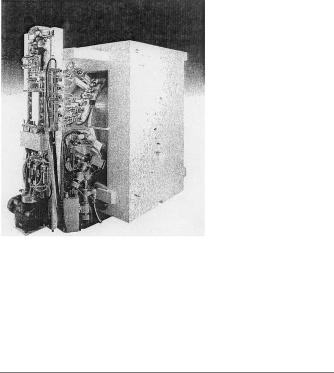
Straight-line machines, such as tandem Van de Graaff units and linear accelerators (linacs), in which the beam moves in a geometric line from low energy ion source to the reaction site, have some disadvantages compared to a cyclotron design. In linear devices, length is generally proportional to the desired energy so as to make the machine difficult to house: particularly in a clinical setting. The clinical cyclotron is small enough to fit within a medium-sized room as shown in Fig. 1. Second, the high voltage needed to accelerate the proton or other ion may be difficult to maintain over the length of the straightline device. Electric breakdowns not only interrupt accelerator operation, they may also damage the internal electrodes.
In order that the appropriate nuclear reaction is possible, the proton beam must strike an isotopically purified target. This may occur within the cyclotron or in a separate chamber external to the accelerator. The latter method is preferred as it permits easier access to the resultant product and rapid switching of one target with another as the reactions are varied. External target locations also reduce the radiation level inside the accelerator. In the 123I example shown above, the target is a foil of highly purified Te metal; this is an isotope that is 5% abundant in natural tellurium.
Unlike linear machines, beam extraction into the target chamber can be problematic for a cyclotron since the ion being accelerated is moving in a stable circular orbit. Traditionally, extraction was done using an electrode. A more effective way to extract protons from the vacuum chamber is to initially attach two electrons to each proton to form an H ion. This molecular species is accelerated until it reaches the correct reaction energy and a corresponding outer orbit. At this point, the circulating negative hydrogen ion is allowed to hit a so-called stripper foil that removes both electrons and converts the ion back to an ordinary proton (Hþ). The proton is not geometrically stable at that radius and field and is magnetically led out of the cyclotron’s vacuum chamber and into the target chamber for the desired reaction.
In addition to longer lived radionuclides, such as 123I, 67Ga, and 201Tl, cyclotrons are conventionally used to manufacture short-lived radionuclides for positron emission tomography (PET) imaging. The latter include 11C (20 min half-life), 13N (10 min), and 15O (2 min). Commercially, the most common product is 18F (110 min) for use in fluorodeoxyglucose (FDG) as described below. Because of the several minute half-lives of the first three of these labels, it is necessary that the cyclotron is available on-site within the nuclear pharmacy. With 18F production, the accelerator may be more remote; perhaps as far as an hour’s drive from the clinical site so that fluorine decay does not appreciably reduce the delivered activity.
NUCLEAR MEDICINE INSTRUMENTATION |
93 |
Figure 1. Medical cyclotron.
SYSTEMATICS OF RADIATION DETECTION
Detection Methods for Ionizing Radiation
Ionizing radiation is detected using electrons liberated within a sensitive volume of a detector material. All three classical states of matter, gas, liquid, and solid have been used as an ionization medium. Table 2 lists examples of each state and the devices associated with it. Most materials have ionization energies on the order of 30 eV per electron–ion pair. In solid-state semiconductors, such as Si or Ge, electron–hole pairs can be formed using 3 eV. This lower value means that semiconductors can provide many more ( 10 ) ionization events for a given photon or electron energy. Such an increased number of events in
turn yields improved statistical certainty that the particle has activated the counter. High thermal noise levels and elevated costs of large arrays of semiconductors have limited their use clinically.
Spectrometry
Signals of various sizes can arise in the detection process. Radionuclide counting depends on selection of the appropriate signal in a milieu of background radiation and other sample decays. For example, the technologist may have to count several beta emitters simultaneously or to detect a given gamma ray energy among many other emissions. Figure 2 shows a gamma spectrum from 137Cs; both
Table 2. Detector Materials used to Measure Ionizing Radiation
|
|
Energy per |
|
|
State of Matter |
Material |
Ionization, eV |
Device |
Application |
|
|
|
|
|
Gas |
Argon |
32 |
Dose calibrator |
Photon activity assay |
|
Air |
32 |
Ion chamber |
Exposure level measurement |
Liquid |
Scintillation fluid (toluene) |
30 |
Liquid counter |
Beta assay in biological samples |
Solid |
NaI (Tl) |
30 |
Gamma camera or probe |
Photon counting |
|
Si (Li) |
3 |
Solid-state probe |
Photon and beta counting |
|
LiF (Tl) |
30 |
TLD (Thermoluminescent |
Radiation safety |
|
|
|
dosimeter) |
|
|
|
|
|
|

94 NUCLEAR MEDICINE INSTRUMENTATION
Figure 2. Energy spectrum of 137Cs as measured by a NaI(Tl) probe.
Compton scattering and photoelectric effect (PE) are observed in this probe made of NaI (Tl).
In the PE, all of the photon energy is given over to an electron–ion pair in the absorbing material. Compton scatter may go on inside the patient prior to the photon coming into any detection system. In such cases, the direction and energy of the quantum may be changed so that an unwanted source may contribute to the counting process. Photon energy analysis is used to guard against such events in imaging; if the energy is seen to be reduced from that of the expected value, an electronic discriminator circuit rejects the ionization event. This pulse height analysis (PHA) is common to all nuclear detector systems and is described for imaging devices below.
ONE-DIMENSIONAL NUCLEAR MEDICINE DETECTORS
Well Counters
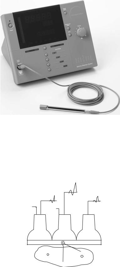
The most primitive instrument for photon detection is the counter or probe. In this case, a NaI(Tl) crystal is generally used to form a single large scintillation detector. In the scintillation process, the ionization event within the crystal is converted to visible light with a decay time on the order of 2 ms or less. Note that NaI is hygroscopic so that isolation of the crystal from the atmosphere is required. A reflective cap of Al is generally used as part of this hermetic seal. Resultant scintillation light is amplified by photomultiplier (PM) tubes to yield an electric signal proportional to the total amount of visible light. Well counters have the crystal in a hollow (cup) shape with the sample within the cup to maximize geometric sensitivity. Shielding is provided by an external layer of lead so as to reduce background counts. This is particularly important in a laboratory or clinical context. A mobile combination of well counter and probe system is shown in Fig. 3. Applications include sample assay using a standard source to give absolute values to the amount of detected activity. Counting experiments may involve patient tissue specimens obtained from the surgeon or animal organs obtained during measurement of biodistributions. Radiation protection is an additional application, whereby surface swab samples are counted to see if contamination is removable and possibly being spread around a lab or clinical area.
A second type of well counter, using high pressure Argon gas as the detector, is the dose calibrator. This device is
Figure 3. Well counter and probe mounted on a mobile chassis.
used in all nuclear pharmacies and clinics to measure the amount of radioactivity (mCi or MBq) in the syringe prior to administration via injection into a patient’s vein. A curie is defined as 3.7 1010 decays per second and a bequerel is one decay per second. Standards are used to calibrate the device at the relevant energy of the radiopharmaceutical. Since the walls of the counter stop alpha and beta radiation, a dose calibrator generally may be used only for the photon component of the decay radiation. One exception is the assay of very high energy beta emitters, such as 90Y or 32P. In these cases, the betas give off a continuous spectrum of X rays of appreciable energy while they are decelerated before coming to rest. Such brake radiation (bremsstrahlung in German) may be detected quantitatively to calculate the amount of high energy beta emitter present in the syringe. Lower energy beta emitters, however, present difficulty in quantitative assays and generally require a different strategy for detection.
Liquid scintillation (LS) counters are a third form of well counter. Here, the beta emitter is dissolved into a liquid hydrocarbon that has been doped so as to produce scintillations suitable for PM detection. These devices have wide application in the quantitative assay of low energy beta emitters used for In vitro biological research. Radionu-
clides of interest include 3H (Ebeta max ¼ 18 keV), 14C (155 keV) and 35S (167 keV). Energies cited refer to the
kinetic energy of the betas. These labels are generally used in type II labeling as shown in Table 1. Multiple samples are sequentially measured for a fixed counting interval by lowering the tube containing mixed scintillator and radioactive material into a darkened space viewed by one and probably two PM tubes. The sample is dissolved in a liquid (usually toluene), which is activated with small amounts of fluors, such as PPO (2,5-diphenyloxazole) and POPOP (4- bis-2,5-phenyloxazolyl) benzene as solutes so as to provide visible light upon being struck by the electrons released during decay. Standards are included in the experimental
High voltage
PM tube
NaI
Signal
Pb
Figure 4. Operating principle of the clinical probe. Note that the observed field of view increases with distance from the opening of the collimator.
run to give absolute values for the activity. Efficiencies may approach 90% or more for moderately energetic betas. Reduction (quenching) of the light output due to solvent impurities and biological molecules within the sample can significantly affect the results and are accounted for by using standards.
The addition of fluors may not be needed to count very high energy beta particles. If the beta speed exceeds that of light in the solvent (Eb max > 0.26 MeV in water), a photon shock wave is produced in the medium. Termed Cerenkov radiation, the emitted light is analogous to that of the acoustic wave or sonic boom produced by an aircraft exceeding the speed of sound. An observer may use Cerenkov light, which includes a continuum of visible and ultraviolet (uv) photons, to directly quantitate beta activity in the sample.
Probes
Clinical probes contain a planar crystal, usually a right circular cylinder, placed at the end of a long, shielded tube called a collimator. The central field of view is typically on the order of a circle 10 cm in diameter. The collimator is another right circular cylinder so that the total field observed increases with distance from the opening. Since the patient has a relative small thickness, on the order of 30 cm or less, this expanding view is not detrimental to the resultant clinical counting experiments. Such static NaI (Tl) devices are routinely used in measurements of thyroid uptake of radioactive 123I as described above. Figure 4 contains a cross-section through a typical probe. With a single probe giving a result of activity for a relatively small, fixed field of view, it is necessary that sets of several probes be employed for measurement in an extended or spatially variable organ.
Conformal arrays have been used to yield information on regional cerebral blood flow (rCBF) in patients. Sets of 10 or more detectors have been arranged around the patient’s skull so as to measure regional accumulation of perfusion tracers, such as 133Xe in the brain. Because of the low gamma energy (81 keV) of 133Xe, a given probe essentially views only physically adjacent tissues in rCBF counting. Such arrays led to the discovery that regional brain– blood flow varied with the mental task that the patient was performing during the time of observation. In this application, it is necessary that the intervening scalp blood flow be subtracted from the time–activity curves for each region. Tomographic methods such as PET do not suffer from this
NUCLEAR MEDICINE INSTRUMENTATION |
95 |
limitation. The PET flow measurements have confirmed the probe rCBF results and generalized them to other aspects of brain blood flow and metabolism during conscious and subconscious thought processes.
A more recent probe application is the detection and uptake measurement of so-called sentinel lymph nodes in melanoma, breast, and other cancer patients. These sites are defined as the first draining node associated with the lesion. They are located following a near-primary injection of a 99mTc-labeled cluster of sulfur colloid particles. Particle sizes up to 1 103 nm may be used. Of necessity for spatial resolution, the hand-held probe has a greatly reduced field of view, on the order of a few millimeters, and may be driven by battery power for convenience in the operating room (OR). Because of size limitations at incision sites, such probes may be of the solid-state type, whereby the ionizing event is converted to an electronic signal directly without the necessity of PM tube signal amplification. At present, CdTe and CsI(Tl) detectors have been incorporated into clinical probe systems. In the latter case, a photodiode is used in lieu of a PM tube to provide miniaturization of the device. An example of a surgical probe is shown in Fig. 5. For use in the OR, the device is usually gas sterilized, and then placed into a plastic sleeve before being put into an operating field.
Similar probe applications can involve radiolabeled antibody proteins used to locate small metastatic lesions in cancer patient after removal of their primary tumor. This has been termed radioimmune-guided surgery (RIGS). By measuring the gamma activity per gram of excised tissue, the radiation oncologist may estimate the radiation dose achievable with that patient’s disease if radioimmunotherapy (RIT) were eventually utilized. In the case of RIT, a beta label is attached to the antibody in lieu of the gamma label used in localization if the radionuclide label does not emit both types of ionizing radiation. Probe-guided biopsy allows direct treatment planning for the RIT procedure that may follow.
Probes are also available for positron detection in the OR. This measurement assures the surgeon that the resection has taken out all of the suspect tissue that has been previously located using a FDG imaging study and a PET scanner. Because of the presence of both annihilation 511 keV photons and positrons, some correction mechanism is necessary for these instruments. A dedicated microprocessor attached to the detector system will provide this information if the probe has separate sensitive elements for positrons plus photons and for photons alone so that a subtraction may be done in real time.
TWO-DIMENSIONAL DETECTORS
Rectilinear Scanners
Because of the limited field of view of single probes, it was once considered clinically relevant for such devices to be mounted on a motor-driver chassis so as to pass in raster fashion over an entire organ. The trajectory of the probe in this context is the same as a gardener mowing the lawn. A simple thyroid probe in this application would prove problematic since it is focused at infinity; that is, observes all
96 NUCLEAR MEDICINE INSTRUMENTATION
Figure 5. Operating room probe. Miniaturization is dictated by the need to minimize the incision site at the sentinel lymph node. With robotic developments, even smaller designs will be necessary.
tissues from one side of the patient through to the opposite side. It can be used on the thyroid since no other organ taking up radioiodine usually lies within the neck region. In order to generally restrict the depth of the field of view, focused (converging) collimation was developed for rasterdriven rectilinear scanner systems so that only emitters at a fixed distance were detected with relatively high efficiency. Dynamic studies, whereby activity was imaged during its physiological motion within the body, were difficult with this device unless the kinetics were significantly slower than the total raster scan time. Today the rectilinear scanner is a historical artifact that is no longer used in the clinic because of the development of the gamma camera. A camera allows both static and dynamic imaging over a reasonably large field (50 cm) without requiring movement of the detector assembly.
Gamma Cameras
H. Anger, in the late 1950s, avoided most of the scanner problems by inventing a gamma camera. As in the probe example, a right circular cylinder of NaI(Tl) was used to detect the photon. However, instead of a single PM tube, a hexagonal array of such tubes was employed to determine (triangulate) location of a given scintillation within the detector’s lateral (x, y) dimensions. This fundamental principle is illustrated in Fig. 6. In order to spread the light somewhat more uniformly over the PM cathode, a light pipe (diffuser) is generally interposed between scintillation crystal and photomultiplier array. Localization was originally done with an analogue computer measuring the relative signal strength from each of a set of PM tubes. A second type of processing occurs with the sum of the PM signals. An energy window is set so that only photons having
energy within a prespecified range are recorded as true events. The window is sufficiently wide, for example,10%, that most signals arising from PE absorption of a monoenergetic gamma are recorded, but other photons, such as those scattered in the patient, are rejected. If the radionuclide emits several different photons, separate energy windows are set to count each energy level. The sum of all counts within all windows is then taken as the clinical result.
The original camera had cylindrical geometry arising from the single-crystal shape. Modern cameras generally have rectangular NaI(Tl) detectors made by combining annealed crystals of relatively large size allowing the
HV
HV
HV 
PM1 |
PM2 |
PM3 |
NaI(Tl)
Patient
Figure 6. Principle of the Anger gamma camera. If no collimation is included (as shown) there is ambiguity of decay position.
entire width of the patient to appear in one field of view. The ensemble of crystal, multiple PM tubes, and associated computer electronics is referred to as the camera head. It is usually in the form of a rectangular solid and is mounted on a gantry allowing rotation and translation with respect to the patient bed. In the latter case, the motion is one dimensional (ID).
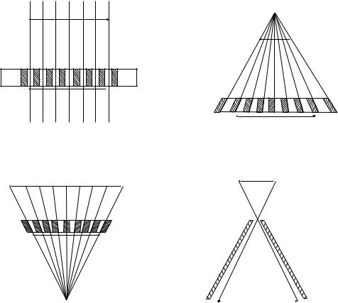
In the absence of directional information, a photon coming from anywhere within the entire hemisphere above the detector may impact the same position on the camera face. To remove the ambiguity, it is necessary that a collimator be provided between the detector crystal and the radioactive object(s). A collimator projects the activity distribution onto the crystal face. Essentially, this is a shadow or projection of the radioactivity distribution. Four standard types of collimators are shown in Fig. 7. The most common of these in clinical use is the parallel-hole type that is focused at infinity; that is, only passes parallel photons (rays) coming from the tissue of interest. Notice that the image and object size are equal in this case (magnification, M, ¼ 1). This is essentially the same geometry used in the thyroid probe. Divergent collimators minify (M < 1) and convergent collimators magnify (M > 1) radioactive objects being imaged. The terms divergent and convergent refer to the point of view of the camera crystal. Convergent collimation is focused at a point in space; this is the same type of system used in the rectilinear scanner described above. However, in the camera case, the
NUCLEAR MEDICINE INSTRUMENTATION |
97 |
focal point is on the other side of the patient where this is no activity. Pinhole collimation may lead to either magnification or minification depending on the location of the object relative to the pinhole aperture.
Efficiencies of all collimators are relatively poor with pinholes becoming the worst at extended distances from the camera face. Typical values are on the order of 1 10 4 for commonly used parallel-hole types. Thus, if an experimenter deals with a very flat (essentially 2D) source, such as a thin radioactive tissue sample, it is better to simply remove all collimation and use the intrinsic localizing capability of the bare crystal and attached PM system. A transparent plastic sheet should be placed between source and camera fact to minimize possible contamination.
Every collimator is designed to be effective at a given photon energy. Lead septae in the device are effectively four to five half-value layers for the quantum of interest. A half-value layer is that thickness of material that reduces the intensity of gamma radiation by a factor of 2. Thus, using a collimator designed for high energy photons in the case of a relatively low energy emitter will lead to both lower efficiency as well as poorer image quality. For radionuclides emitting several different photons, the collimation must be appropriate for the highest gamma ray energy being measured. If this is not done, a hazy background of events due to these photons passing through the collimator walls will obscure the image.
Object
 Object
 Image
Image
A C
 Object
 Object
Image
|
|
|
Figure 7. Four standard types of |
|
|
Image |
|
|
|
collimators used on the gamma
B |
D |
camera. |
98 NUCLEAR MEDICINE INSTRUMENTATION
Spatial resolution of gamma camera systems is on the order of 1 cm near the collimator surface, but generally becomes worse with increasing source depth inside the patient. When the count rate becomes extremely elevated, however, the localizing algorithms of such devices can be confused by multiple simultaneous scintillations with resulting imaging artifacts and reduced resolution. Most clinical protocols recognize this limitation by keeping the count rate at or below 5 104 counts per second (cps).
Because absolute measurement of resolution as well as object (organ) size is important, it is useful to image point sources of radiation for testing each camera-collimator system. This test object may be a set of small (1 mm) radiation sources of the imaged radionuclide having a known spacing. Resolution and object size in any resultant film or digital image can be defined directly using such devices. Variation with depth (patient thickness) and distance from the collimator may also be evaluated.
Digital Processor Applications Within the Camera Head
Anger’s patented design originally relied on an analog computer to position the scintillation flash within the lateral dimensions of the NaI(Tl) crystal. Each scintillation event was weighted by location and signal amplitude of the several recording PM tubes. One of the original problems of the design has been the non-uniformity of response due to intrinsic and temporal variation in PM tube and other analog circuit components. In modern camera heads, digital processors are used to position the scintillation flash as well as perform spectroscopic analyses in real time on the detected events. Such dedicated processors inside the camera head observing individual PM tubes can greatly improve the uniformity so that the central field of view (CFOV) can have uniformities approaching 2%. Uniformity is particularly important for 3D imaging involving rotation of the camera head as described below. Values for each head are measured regularly with a flat source of radioactivity of an appropriate energy for most of the clinical imaging. Cobalt-57 is the radionuclide of choice for this procedure since it is close in emission energy (120 keV) to the common radiolabel 99mTc (140 keV) and has an extended half life of 270 d.
Note that communication formats are now available for information transfer between cameras and external computers. The digital imaging and communications in medicine (DICOM) standard is the international format for this transfer of information. This information may be used to produce comparisons of nuclear and other images to improve the diagnostic process.
Types of Acquisition from Gamma Cameras
One very important choice made by an operator prior to any camera study is the method of photon event recording in any external computer or work station memory. It is most common to acquire each scintillation as an event or count at coordinates (x, y). With total time of acquisition fixed at some realistic (patient-derived) limit, these events are added at their spatial positions to form a single digital image. This method of data recording is called frame mode. It is, by far, the most common type of camera data acquisition.
It may be that the timing of the tracer movement is either very rapid or uncertain for the patient–study. In that case, one may a priori choose list mode acquisition whereby each event is recorded as a triplet: (x, y, t) with computer clock time (t) included. After all events are list mode recorded, the operator or clinician may reconstruct the study in any sequence of time frames that is desired. For example, the first minute may be assigned to image 1, the second minute to image 2, and minutes 3–10 to image 3. Each of these images would appear to the reader as if they were taken in frame mode over that interval. Such an allotment may be revised subsequently as clinical questions arise. Large memory sizes are clearly useful if list mode imaging is to be pursued. Modern cameras often do not offer the possibility of list mode acquisitions, but instead rely on use of high speed frame-mode data recording.
A special type of frame mode acquisition is the gated study. Here, data are acquired in synchrony with a repeated physiological signal, usually the patient ECG. The R-wave-to-R-wave interval is predivided into a number (n) of equally spaced segments. Data obtained during time segment 1 of the cardiac cycle are placed into image 1, from time segment 2 into image 2, and so on. The result is a closed loop of n images that shows the beating heart when the gating signal is derived from the electrocardiogram (ECG).
External computer processing of camera data has been used to generate an additional type of output referred to as a functional image. For example, the clinician may wish to measure the rate of physiological clearance of a radiotracer from individual pixels within a time sequence of organ images. Using the external computer to calculate regional rate constants and to store this array, the resultant functional image displays the relative magnitudes of the computed kinetic values. Using an arbitrary scale, faster clearing regions are shown as brighter pixels. By looking at the functional image, regions of slower clearance can be readily identified and followed post subsequent therapies such as microsurgery for stroke patients.
Gamma Camera Types
Mobile Cameras. Battery-powered Anger cameras may be mounted on motor-driven chassis for use at the bedside or other remote areas. In such cases, the head is generally
smaller than a static camera, on the order of 25 cm in diameter, and the energy range limited to 140 keV (99mTc)
due to shielding weight concerns. Movement up ramps and using elevators would be restricted otherwise. Mobile units are most often utilized in planar heart work and have been involved in the testing of patients under escalating stress such as on a treadmill in cardiology. Patient evaluations in the OR or ICU are other applications of the device. Aside from breast imaging using 99mTc -sestamibi, use of mobile gamma cameras has been limited, however, because of two specific reasons listed below.
Tomographic imaging is generally not possible with the mobile camera due to the difficulty of rotating the device in a rigorous orbit about the patient. In addition, use of high energy gamma labels is not possible for the minimally
shielded detector head. Because of the importance of 3D imaging of the heart (see below), clinical usage has dictated that the more optimal study results if the patient is brought to the nuclear medicine clinic in order that optimal tomographic images be obtained.
Static Single-Head Cameras. The most common camera type, the static single head, is usually a large rectangular device with a NaI(Tl) crystal having a thickness of 6– 9 mm. Larger thicknesses up to 25 mm may be useful for higher energy gammas, but loss of spatial resolution occurs as the PM location of the scintillation becomes more indeterminate. Lateral crystal dimensions are approximately 35 50 cm, although actual external size of the head would be significantly larger due to the necessity of having lead shielding surrounding the detector. This shielding must go both around the detector crystal as well as behind it to prevent radiation coming into the sensitive NaI(Tl) from the direction opposite the patient. Such protection is of importance in a busy clinical situation where more than one study is being conducted simultaneously in a relatively small space. Large rectangular camera heads permit simultaneous imaging over the entire width of a typical patient and allow whole body imaging with a single pass of the detector from the head to the feet. This is essentially an updating of the rectilinear scanner concept although here it is a 1D motion (z).
Images from Single-Head Cameras. Two standard imaging formats are employed with the gamma camera. Regional images, or vignettes, are taken of the organs of interest in the clinical study. A patient complaining of pain in the knee will be placed adjacent to the camera to permit various views of that joint following administration of a
NUCLEAR MEDICINE INSTRUMENTATION |
99 |
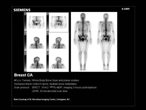
bone-seeking radiotracer, such as 99mTc-MDP. In addition, a whole-body image may be acquired to check for overall symmetry of tracer uptake. An example of the latter is given in Fig. 8. Here, the camera head is driven from the head to the foot of the patient and a series of frame images acquired over a span of 20–30 min. A computer attached to the camera allows these separate images to be seamlessly united to form the whole-body format.
Anger’s camera concept has had one of its greatest impacts in cardiac dynamic imaging, whereby the sequential heart images are stored in a repetitive sequence that is correlated to the ECG signal obtained from the patient as described above. Figure 9 includes a continuous loop of 16 images of the left ventricle during a cardiac cycle using a labeled red cell tracer based on 99mTc. By setting a computer-generated region of interest (ROI) over the ventricle, one can measure the relative amount ejected; that is, the left ventricular ejection fraction (LVEF). Note that absolute amount of the tracer is not needed in the study since it is only a fractional ejection fraction that is of interest to the cardiologist. Irregular heart beats and/or patient motion during the 10–20 min of data taking can make such studies difficult to process.
Other dynamic studies are popular and clinically important. These include the renogram whereby the uptake and clearance of a filtered agent, such as 99mTc-DTPA is measured over a 1 h period. Both kidneys are followed and characteristic times of tracer accumulation and excretion are estimated by the radiologist: often using external computer software. A partial listing of typical studies involving gamma camera image data is included in Table 3.
Multiple-Head Cameras. It is becoming common to use more than one gamma detector head within a single
Figure 8. Whole-body image of a bone scan patient using translation of
the gamma camera from head to foot. A sample of 20 mCi of 99mTc-MDP was
used as the radiotracer for this image taken at 4 h postinjection.

100 NUCLEAR MEDICINE INSTRUMENTATION
Figure 9. A multiple gated (MUGA) study of the left ventricle. The 16 images acquired over a heartbeat are uniformly assigned in time to the R wave-to-R wave cardiac interval. An ejection fraction of 69% was calculated.
supporting gantry (cf. Fig. 10). Speed of data acquisition, in either 2D or 3D mode, is the most important reason for this augmentation. By using two heads in a 2D study, the patient may be imaged from opposing sides simultaneously. Thus, if the organ of interest or tumor site were closer to the back of the patient, one could obtain information from the posterior head that would be useful even if the anterior head showed no discernible uptake sites. Alternatively, anterior and lateral views of an organ system may be obtained simultaneously and serially in a dynamic study of gastric emptying, for example. A second, and very important, application of multiple head camera systems is in more efficient 3D imaging.
THREE-DIMENSIONAL DETECTORS
There are two quite distinct methods to provide 3D imaging in nuclear medicine. If one uses ordinary (nonpositron) gamma-emitters, the strategy is referred to as singlephoton emission computer tomography or SPECT.
SPECT Imaging
Here, the detector head or, more likely the set of two or three heads, is rotated around the patient over an extended arc. This orbit may be a full 3608 arc or may be less due to body habitus or tissue location. One uses the rectangular Anger
Table 3. Representative Gamma Camera Imaging Studies Done in Nuclear Medicine
Study |
Agent |
Label |
Device |
Results |
|
|
|
|
|
Renogram |
DTPA and MAG3 |
99mTc |
Camera |
Kinetic values |
MUGA |
Red cells |
99mTc |
Camera with EKG gating |
Ejection fraction of LV |
Myocardium |
Sestamibi |
99mTc |
Camera |
Bulls eye image of LV |
Bone scan |
MDP |
99mTc |
Camera |
Fracture location. Tumor location |
Lung scan |
Aggregated albumin |
99mTc |
Camera |
Regions of reduced perfusion |
Lung scan |
Aerosolized albumin |
99mTc |
Camera |
Regions of reduced ventilation |
Lung scan |
Xenon gas |
133Xe |
Camera |
Regions of reduced ventilation |
Thyroid imaging |
Iodine |
123I |
Camera |
Uniformity of uptake in gland |
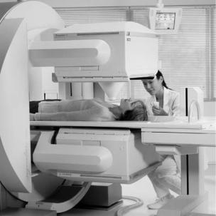
Figure 10. Dual-headed gamma camera. Both detector heads are mounted on the same gantry to allow translation (for whole body) and rotation (for SPECT) of the system. An open geometry permits use of gurneys with this system.
head as described above with the parallel-hole collimation in place. With injected activities on the order of 100–300 MBq, data acquisitions require on the order of 20 min. Patient immobility is necessary. Data may be taken in a shoot- and-step mode at fixed angular intervals or they may be acquired continuously during the rotation. Storage of such vast amounts of information requires a dedicated computer system recording the counts at each spatial position on the head (x,y) and at each angle (y) during the rotation.
Several reconstruction algorithms are available to the technologist to generate the requisite tomographic images of the patient. Corrections for attenuation and Compton scatter must also be applied for the generation of these images. While pseudo-3D images may appear on the computer monitor as an output of the reconstruction, the radiologist will review and file to the picture archival and communication system (PACS) system the transaxial, sagittal, and coronal projections of the activity. It is important to realize that numerical values usually shown in these various projection images are not absolute, but only relative quantities. Quantitative SPECT, in which the numerical pixel value is equal (or at least proportional) to the activity in Bq, requires, in addition to the above corrections, that a set of standard sources of the same radionuclide be imaged along with the patient. Such calibrations can be done simultaneously with the clinical study, but are usually performed as a separate procedure. Figure 11 shows the three projection sets (axial, sagittal and coronal) in the case of a patient having a 99mTc sestamibi myocardial scan of the left ventricle.
PET Systems
Back-to-back photon emission (511 keV each) characteristic of positron decay of a labeling radionuclide has led to the
NUCLEAR MEDICINE INSTRUMENTATION |
101 |
development of PET. While paired Anger camera heads have been used as the detectors, it is much more efficient to use a ring of solid-state scintillation detectors arrayed around the patient. Bismuth germinate (BGO) has been the standard material, but LSO (lutetium orthosilicate) is becoming more popular due to its higher light output and shorter pulse length at 511 keV. In the standard situation, each detector block is broken into separate light emitting substructures that act as individual scintillation detectors. By having a few phototubes observing a separate block of such elements, the number of PMs may be reduced using Anger’s gamma camera principle. Whole body PET scanners may have > 104 individual scintillators arrayed in an open circle or set of rings around the patient bed. Multiple rings are conventional so that several axial sections may be acquired simultaneously over a distances of 10–15 cm. Note that no detector rotation is inherently required since the solid-state system completely encircles the patient. If needed, the bed will be driven along the axis of the detector rings in order to perform extended imaging of the subject. The most common study utilizes FDG with 18F as the radiolabel and covers the patient from head to groin. Sites within the body that metabolize glucose are imaged thereby. Brain and possible tumor areas are important applications of PET glucose imaging. Ambiguity with infection sites is a limitation to this protocol; this is particularly the case in the immune-compromised patient.
Because the two emitted photons are coincident in time and define a line in space, the positron detection process does not, in principle, require collimation (Fig. 12). Using contiguous rings of detectors is the most common system design; if the rings act alone or together as a single detector system defines the two types of imaging that are performed on a PET system. Internal (patient) photon attenuation is taken into account in the reconstruction of the PET image set. This is done using a transmission source of positron emitter, usually 68Ge, to evaluate the patient thickness for the various ray directions at each bed position. Typically, the attenuation correction occurs during the scanning procedure with a short time interval given over to use of the source at each bed location.
Two-Dimensional PET Imaging
A clinical PET scanner is shown in Fig. 13. In 2D PET, every ring of detectors is isolated by tungsten collimation from all but single adjacent rings. Thus, each circle of solidstate scintillators is used in isolation to generate a single axial slice through the patient. This approach yields the highest resolution available in positron tomography with systems having spatial resolutions on the order of 5 mm. Reduction in the amount of scatter radiation is also obtained in 2D images. A FDG image is given in Fig. 14. While described as 2D, the result is actually tomographic and gives the usual projections in the three planes intersecting the patient’s body. In these planes, the precise estimate of resolution depends on the positron’s kinetic energy. One must combine, in quadrature, the positron range in soft tissue with inherent ring resolution to predict the overall spatial distance ambiguity. Higher energy positron emitters will have correspondingly poorer spatial

102 NUCLEAR MEDICINE INSTRUMENTATION
Figure 11. The SPECT image set for a gated myocardial study. In each pair of rows, the upper set
of images gives the stress result, the lower set the resting result. The patient received 30 mCi of 99mTc-sestamibi for the study.
resolution due to the greater range of the positron prior to decay.
Other criteria for the selection of a positron label may be applied; for example, the half-life of the radionuclide. If that lifetime is very short, manufacturing and targeting may take so many physical half-lives that imaging is not possible. Additionally, one should consider the relative probability of bþ emission in the decay scheme. This likelihood may be reduced because of competition with electron capture from the K shell of the radionuclide. Additionally, there is the possibility that other photons may be emitted along with the positrons so as to cause a background effect in the PET scanner. For example, 124I, along with annihilation radiation at 511 keV, also emits ordinary gamma rays with energy in excess of 2 MeV. Such high energy photons readily penetrate collimators to reduce contrast in the images and make quantitation of the absolute radioiodine activity difficult.
Three-Dimensional PET Imaging
When the collimation between PET scanner rings is removed, each circle of detectors can have coincidences with itself as well as with all other detector rings. This mode of operation is referred to as 3D imaging. Spatial resolution is somewhat worse than that of the collimated (2D) case and may be 1 cm or more. However, the added
sensitivity may be very important: particularly if whole body images are to be obtained in a patient with possible multiple sites of interest such as a referral from medical oncology. Sequential PET images of the whole body may be used to evaluate chemotherapy or other interventions. A quantitative method is available for such comparisons.
One feature of PET imaging merits emphasis. In the quality assurance of the positron scanner, the operator will routinely obtain transmission images through a phantom of known size using 511 keV photons from an external source. With this information and calibration using a known activity source, the user may reconstruct radioactivity distributions in the patient with absolute units. Thus, the concentration of positron emitter at a given image voxel can be estimated. Called the specific uptake value (SUV), this parameter is essentially %ID g 1, where ID refers to the injected activity or dose (MBq). The resultant SUV value is a function of time. Two direct consequences result. First, the clinician can make comparisons between organ sites both now and with regard to earlier studies on that patient or relative to normal individuals. Results of therapy may be directly evaluated thereby. The SUV values may even be used to make diagnostic assessments, such as the likelihood of malignancy at the voxel level. In addition, the radiation dose to the entire organ and even to local volumes within the tissue may be directly made with the SUV parameter. This

2-D |
Crystal |
|
|
mode |
Septum |
|
3-D
mode
 Crystal
Figure 12. Principle of a PET scanner. Note that the direction of the annihilation radiation defines a line in space. 2D and 3D configurations are accomplished with and without collimation, respectively.
is in contrast to gamma camera planar data whereby the results may be quantified only with associated calculations that depend upon acquiring a set of images from at least two sides of the patient.
HYBRID IMAGING INSTRUMENTS
Nuclear image information, of either gamma camera or PET type, is limited in that regions of elevated (or reduced) activity are not necessarily identifiable as to anatomic location or even organ type. A patient may exhibit a hot
Figure 13. A clinical PET scanner.
NUCLEAR MEDICINE INSTRUMENTATION |
103 |
Figure 14. A PET image of a breast cancer patient following injection of 10 mCi of FDG. A MIPS projection is shown with areas of elevated FDG appearing as dark foci. Note accumulation in regional lymph nodes near the breast primary.
spot in a planar gamma camera view that could correspond to uptake in a lobe of a normal organ, such as the liver or perhaps to an adjacent metastatic site. Similar arguments may be made with SPECT or PET images. Clinical decisions and surgical options are difficult to determine in this ambiguous context. Radiologists viewing nuclear medicine images are forced to cloak their patient assessments in correspondingly vague spatial terms.
Lack of anatomic correlation has been one of the most difficult issues in the history of nuclear imaging. Physiological data determined with nuclear techniques are considered complementary to anatomical information separately obtained by other imaging modalities such as
104 NUCLEAR MEDICINE INSTRUMENTATION
CT or magnetic resonance imaging (MRI). The radiologist or referring clinician will frequently have to conceptually fuse disparate data sets to help identify the specific organ or tissue where a nuclear tracer uptake zone occurs. Using DICOM and PACS technologies, one may also attempt to digitally overlay nuclear and anatomic images. In this case, however, magnification, rotation, and translation of one image relative to the other must be accounted for with appropriate software and adjustable parameters. Using commercial programs, CT and MRI digital images may be fused to nuclear imaging results using least-squares techniques and an external workstation.
In order to remove this conceptual and computational bottleneck, recent developments in nuclear medicine have included manufacture of hybrid physiologic/anatomic imagers. In this strategy, both devices share a common patient bed so that two types of images are spatially registered and, although successive, nonetheless obtained within a few minutes of each other. Note that the PM tubes of a typical gamma camera or PET system are sensitive to magnetic field effects at the level of the earth’s value; that is, at0.5 G. Yet clinical MRI scanners operate in the range of 1.5–3.0 T (1.5 104 to 3.0 104 G) so that hybrids of MRI and nuclear devices would be problematic. Thus, essentially all of the hybrid systems have involved combinations of nuclear and CT imagers.
SPECT/CT Hybrid Imagers
A logical approach to the issue of radionuclide localization is to have two scanners, one nuclear and one based on X-ray attenuation, located on attached gantries. This pair of devices shares the same patient couch. Because the distances of bed movement can be known within 1 mm or less, the user can identify an uptake volume in the nuclear SPECT image with a geometrically corresponding part of the anatomy as seen via CT scan. Additionally, attenuation corrections may be made more effectively using the CT data to improve SPECT sectional images. Some difficulties remain: (1) the breathing motion of the patient, and (2) possible changes in posture from one sequence to the other during the double imaging procedure. Complementary nature of the two images makes the interpretation of either somewhat clearer.
PET–CT Hybrid Imagers
Analogous to the gamma camera, a PET detector ring imager can be mounted adjacent to a CT scanner to provide registration of images from two modalities. As in the case of SPECT–CT devices, disparities in the speed of the two data acquisitions leads to some remaining ambiguity involving organs that move with respiration such as liver or lungs. While it is possible to hold one’s breath for a CT scan, the PET whole body nuclear imaging time remains on the order of 20–30 min to preclude such possibilities for the emission segment of the study. A set of hybrid images and their superimposition are given in Fig. 15.
Radiation therapy treatment planning has been one of the primary beneficiaries of hybrid imaging devices. It may be that some mass lesions visible via CT or other anatomic imagers are necrotic or at least not active meta-
bolically. This result can most clearly be seen in the fused image so that the more physiologically active sites may be treated with higher external beam doses. Likewise, with appropriate resolution, the radiation oncologist may elect to treat part of a lesion that has heterogeneous tracer uptake in an effort to spare contiguous normal (albeit sensitive) sites, such as in the lung, spinal cord, or brain. Those segmental regions of a tumor mass that are metabolically active may be targeted with external beam therapy using a number of linear accelerator strategies including conformal therapy, intensity modulated radiation therapy (IMRT) and tomotherapy using a rotating radiation source.
ANIMAL IMAGING DEVICES
As indicated previously, the growth of nuclear medicine is limited by availability of specific radiopharmaceuticals. Historically, useful agents were often discovered (sometimes by accident) and were almost never invented. This strategy is inefficient and modern molecular biologists and pharmacists attempt to directly engineer improved tracers for a given clinical objective; that is, imaging or therapy of a particular tissue or tumor type. A specific molecule or cellular organelle is generally the target in these efforts. Molecular imaging has become an alternative name for nuclear medicine. After initial protein or nanostructure development is completed, the next task is the determination of the relative usefulness of the prototype in an animal study. Usually, this work involves mouse or rat radiotracer biodistributions involving sacrifice of 5–10 animals at each of a number of serial times. If multiple time points and comparison of various similar radiotracers are involved, numbers of mice may approach thousands for the development of a single radiopharmaceutical.
It is more analogous to clinical procedure if serial images of the same animal are obtained during the course of the research study. Far fewer animals are required and the data are more homogenous internally. Imaging with standardsized nuclear technology is generally unsatisfactory due to poor spatial resolution associated with typical gamma cameras (1 cm) or PET scanners (0.5 cm). Early investigators had utilized a suitably small pinhole collimator and gamma camera combination on mouse and rat imaging studies. By collimator magnification, the image can be made large enough that the internal structures can be resolved. As noted previously, magnification and sensitivity depend on distance from the pinhole so that quantitative interpretation of these images was difficult. Sensitivity of pinhole imaging was likewise low so that relatively large amounts of activity were required for the study. It is more effective if a dedicated, high efficiency, animal-size imaging device is designed for the experimental species. Such instruments have been developed for planar and SPECT gamma camera as well as PET imager systems.
Animal Gamma Cameras
Imaging a 10 cm mouse is best done with a gamma camera having approximately that sized crystal. Rather than employing a hexagonal array of multiple, miniaturized PM tubes to locate the scintillation, an animal camera
NUCLEAR MEDICINE INSTRUMENTATION |
105 |
Figure 15. The CT–PET hybrid image showing respective CT, PET, and combined images. Clarity of location follows from the last of these results.
relies on the use of a single spatially sensitive PM tube. This device sends both x and y coordinates and the energy of the scintillation to a dedicated computer. Otherwise, the murine camera is operated essentially identically to the full-size version. Parallel-hole collimation is most common, although pinholes may be used to form highly magnified images of murine organs, such as the liver, kidneys, or even the thyroid. Figure 16 illustrates the last of these targets for a mouse receiving a tracer injection of 125I to enable imaging of the murine thyroid. SPECT imaging is also possible; it is accomplished by rotating a rigorously constrained mouse or other small animal within the field of view of the camera. The usual projections, coronal, sagittal and transaxial are then available.
Animal PET Imagers
Miniature PET scanners have become of importance to the development of new radiopharmaceuticals. Here, a ring of BGO or LSO crystals is installed in a continuous cylinder extending over the entire length of the mouse. Spatial resolution is on the order of 2 mm or less over the 12 cm axial dimension. A sample image is given in Fig. 17 where a number of coronal sections are superimposed to improve the image statistics. Both 18F-FDG and 64Cu labeled to a
modified antibody protein called the minibody were the positron emitters used in this study. Again, as in the clinical case, the PET images are intrinsically tomographic unlike the gamma camera results. Therefore, the PET animal imagers have a theoretical advantage in biodistribution
Figure 16. Animal gamma camera image of a mouse thyroid. Iodine-123 was used as the tracer with a pinhole collimator to obtain an image of the normal organ.