

- •VOLUME 5
- •CONTRIBUTOR LIST
- •PREFACE
- •LIST OF ARTICLES
- •ABBREVIATIONS AND ACRONYMS
- •CONVERSION FACTORS AND UNIT SYMBOLS
- •NANOPARTICLES
- •NEONATAL MONITORING
- •NERVE CONDUCTION STUDIES.
- •NEUROLOGICAL MONITORS
- •NEUROMUSCULAR STIMULATION.
- •NEUTRON ACTIVATION ANALYSIS
- •NEUTRON BEAM THERAPY
- •NEUROSTIMULATION.
- •NONIONIZING RADIATION, BIOLOGICAL EFFECTS OF
- •NUCLEAR MAGNETIC RESONANCE SPECTROSCOPY
- •NUCLEAR MEDICINE INSTRUMENTATION
- •NUCLEAR MEDICINE, COMPUTERS IN
- •NUTRITION, PARENTERAL
- •NYSTAGMOGRAPHY.
- •OCULAR FUNDUS REFLECTOMETRY
- •OCULAR MOTILITY RECORDING AND NYSTAGMUS
- •OCULOGRAPHY.
- •OFFICE AUTOMATION SYSTEMS
- •OPTICAL FIBERS IN MEDICINE.
- •OPTICAL SENSORS
- •OPTICAL TWEEZERS
- •ORAL CONTRACEPTIVES.
- •ORTHOPEDIC DEVICES MATERIALS AND DESIGN OF
- •ORTHOPEDICS PROSTHESIS FIXATION FOR
- •ORTHOTICS.
- •OSTEOPOROSIS.
- •OVULATION, DETECTION OF.
- •OXYGEN ANALYZERS
- •OXYGEN SENSORS
- •OXYGEN TOXICITY.
- •PACEMAKERS
- •PAIN SYNDROMES.
- •PANCREAS, ARTIFICIAL
- •PARENTERAL NUTRITION.
- •PERINATAL MONITORING.
- •PERIPHERAL VASCULAR NONINVASIVE MEASUREMENTS
- •PET SCAN.
- •PHANTOM MATERIALS IN RADIOLOGY
- •PHARMACOKINETICS AND PHARMACODYNAMICS
- •PHONOCARDIOGRAPHY
- •PHOTOTHERAPY.
- •PHOTOGRAPHY, MEDICAL
- •PHYSIOLOGICAL SYSTEMS MODELING
- •PICTURE ARCHIVING AND COMMUNICATION SYSTEMS
- •PIEZOELECTRIC SENSORS
- •PLETHYSMOGRAPHY.
- •PNEUMATIC ANTISHOCK GARMENT.
- •PNEUMOTACHOMETERS
- •POLYMERASE CHAIN REACTION
- •POLYMERIC MATERIALS
- •POLYMERS.
- •PRODUCT LIABILITY.
- •PROSTHESES, VISUAL.
- •PROSTHESIS FIXATION, ORTHOPEDIC.
- •POROUS MATERIALS FOR BIOLOGICAL APPLICATIONS
- •POSITRON EMISSION TOMOGRAPHY
- •PROSTATE SEED IMPLANTS
- •PTCA.
- •PULMONARY MECHANICS.
- •PULMONARY PHYSIOLOGY
- •PUMPS, INFUSION.
- •QUALITY CONTROL, X-RAY.
- •QUALITY-OF-LIFE MEASURES, CLINICAL SIGNIFICANCE OF
- •RADIATION DETECTORS.
- •RADIATION DOSIMETRY FOR ONCOLOGY
- •RADIATION DOSIMETRY, THREE-DIMENSIONAL
- •RADIATION, EFFECTS OF.
- •RADIATION PROTECTION INSTRUMENTATION
- •RADIATION THERAPY, INTENSITY MODULATED
- •RADIATION THERAPY SIMULATOR
- •RADIATION THERAPY TREATMENT PLANNING, MONTE CARLO CALCULATIONS IN
- •RADIATION THERAPY, QUALITY ASSURANCE IN
- •RADIATION, ULTRAVIOLET.
- •RADIOACTIVE DECAY.
- •RADIOACTIVE SEED IMPLANTATION.
- •RADIOIMMUNODETECTION.
- •RADIOISOTOPE IMAGING EQUIPMENT.
- •RADIOLOGY INFORMATION SYSTEMS
- •RADIOLOGY, PHANTOM MATERIALS.
- •RADIOMETRY.
- •RADIONUCLIDE PRODUCTION AND RADIOACTIVE DECAY
- •RADIOPHARMACEUTICAL DOSIMETRY
- •RADIOSURGERY, STEREOTACTIC
- •RADIOTHERAPY ACCESSORIES
252 PHANTOM MATERIALS IN RADIOLOGY
85.Barbour RL, Graber H, Lubowsky J, Aronson R. Monte Carlo modeling of photon transport in tissue (PTT) [I. Significance of source-detector configuration; II. Effects of absorption on 3-D distribution (3DD) of photon paths; III. Calculation of flux through a collimated point detector (CPD); IV. Calculation of 3-D spatial contribution to detector response (DR); V. Model for 3-D optical imaging of tissue]. Biophy J 1990;57:381a–382a.
86.Gru¨ nbaum FA. Tomography with diffusion. Inverse methods in Action In: Sabatier PC, Editor. (Proceedings of 1989 Multicennials Meeting on Inverse Problems. New York: SpringerVerlag; 1990; 16–21.
87.Barbour RL, Lubowsky J, Aronson R. Method of Imaging a Random Medium, US pat. 5,137,355; awarded 8/11/92.
88.Wilson BC, Sevick EM, Patterson MS, Chance B. Timedependent optical spectroscopy and imaging for biomedical applications. Proc IEEE 1992;80:918–930.
89.Barbour RL, et al. Temporal Imaging of Vascular Reactivity by Optical Tomography. In: Gandjbakhche AH, editor. Proceedings of Inter–Institute Workshop on In Vivo Optical Imaging at the NIH. (Optical Society of America, Washington, (DC); 1999), pp. 161–166.
90.Barbour RL, et al. Optical tomographic imaging of dynamic features of dense–scattering media. J Opt Soc Am A 2001;18: 3018–3036.
91.Schmitz CH, et al. Instrumentation for fast functional optical tomography. Rev Sci Instr 2002;73:429–439.
92.Wang X, et al. Noninvasive laser-induced photoacoustic tomography for structural and functional in vivo imaging of the brain. Nature Biotechnol 2003;21:803–806.
93.Kruger RA, Stantz KM, Kiser WL. Thermoacoustic CT of the Breast. Proc SPIE 2002;4682:521–525.
94.Ku G, Wang L-H. Deeply penetrating photoacoustic tomography in biological tissues enhanced with an optical contrast agent. Opt Lett 2005;30:507–509.
95.Weissleder R, Ntziachristos V. Shedding light onto live molecular targets. Nature Med 2003;9(1):123–128.
See also CUTANEOUS BLOOD FLOW, DOPPLER MEASUREMENT OF; IMPEDANCE PLETHYSMOGRAPHY.
PET SCAN. See POSITRON EMISSION TOMOGRAPHY.
PHANTOM MATERIALS IN RADIOLOGY
YOICHI WATANABE
C. CONSTANTINOU
Columbia University
New York, New York
INTRODUCTION
What is Phantom?
Radiation has both particle and electromagnetic wave nature. Radiation carries energy; hence, upon striking the human body, radiation deposits the energy in the human tissue. This interaction consequently can damage the tissue by causing strand breaks in genetic molecules called deoxyribonucleic acid (DNA) in nucleus of living cells. Such damages are considered a major cause of cancers.
Radiation, such as X rays, (g rays, electrons (or b- particles), helium ions (or a-particles), and neutrons were
discovered in late nineteenth century to early twentieth century. Since that time scientists and engineers invented and developed beneficial applications of radiation by taking advantages of the penetrating and damaging power of the radiation. Medical uses are the most noticeable applications of radiation. Radiation is used to diagnose and cure human illness.
Radiologists use X rays and other particulate radiation in hospitals and clinics to diagnose disease through imaging diseased sites. Radiation oncologists use X rays, electrons, and other forms of radiation available in radiation oncology centers to cure cancer.
While radiation is useful, careless use of radiation can lead to harmful effects on the health of people. Therefore, it is quite important to carefully evaluate the distribution of radiation energy absorbed by human tissue (or dose) during the radiological procedures. If the potential radiation damage is not well understood, clinical uses of new radiation sources without careful and thorough evaluation must be avoided. Placement of radiation measurement instrumentation in the human body is not easy, thus hampering precise dose measurements. Therefore, radiation scientists developed simulated human bodies or organs, herein called phantoms, to evaluate actual radiation doses. The phantoms are used to estimate radiation dose and transmission (or attenuation) of radiation in the human body for radiological studies.
Phantom materials for radiology should mimic the radiological characteristics of tissues. The homogeneity of radiological characteristics over the phantom is very important. Often the shape of the phantom should mimic the shape of a human body or a part of the body. Hence, the material should be easily made into various shapes and it should be easy to machine the material. The materials should maintain the mechanical integrity and the radiological characteristics for a long time.
Historical Background
To simulate radiation transport processes in human body, scientists developed phantoms made of tissue mimicking materials. The phantom should be made of material that absorbs and scatter radiation in the same way as the real tissue. Spires showed that the phantom material should have the same density as tissue and contain the same number of electrons per gram (1).
Water was the first material to be used as a tissue substitute in radiation measurements by Kienbock (2). Baumeister introduced wax in 1923 (3). The first formulated solid, called Siemen’s Wax, composed of paraffin wax and magnesium oxide as a corrective filter, was reported by Ott in 1937 (4). Several similar wax-based products were subsequently introduced in Europe and North America, including MixD (5), Harris Wax (6), and M3 (7). Many phantoms comprised of either simple stacked sheets or more complex body-like structures have been constructed from these latter materials.
Plastics and rubbers have found an increasing application in the specialty of tissue simulation. From the polyethylene-based Markite (8) stemmed the conducting
plastics of Shonka et al. (9) and polyurethane systems of Griffith et al. (10). The last three products have been used in the manufacture of elaborate anthropomorphic body phantoms with airways, simulated lungs, and embedded skeletons. An important elementally equivalent liquid system was introduced by Rossi and Failla (8). A mixture of water, glycerol, urea, and sucrose was used to match an approximate formula for soft tissue. This mixture was simplified by Goodman (11) and extended to more complex elemental formulas (12). Of the tissue substitutes introduced before 1970, only a handful had radiation absorption and scattering characteristics within 5% of those of the corresponding real tissues over extended energy range, and these included most of the above-mentioned phantom materials. The most important of them was water. Fortunately, it was readily available and cheap. An extensive program of research and development was initiated at St. Bartholomew’s Hospital in London in 1970. Over 160 tissue substitutes were formulated, simulating a wide range of body tissues. Liquid, gel, solid, and particulate systems were produced for use with photon and particulate radiations (13–16). Other groups also developed tissue equivalent materials. Herman et al. used polyethylene to develop water-equivalent material, as well as fat and muscle materials in 1980s (17–19). Homolka et al. used polymer powders together with suitable additives to adjust photon attenuation (20,21). They created adipose, muscle, bone, and water equivalent materials, which simulate radiological characteristics of tissues for low energy photons, that is, energy < 100 keV for diagnostic X rays. Latest work includes development of tissue equivalent materials for pediatric radiology by Bloch et al. (22). Suess et al. manufactured a phantom material based on polyurethane resin for low contrast resolution measurements of computed tomography (CT) scanners (23). Iwashita used polyurethane resin mixed with CaCO3 to create cortical and cancellous bones (24). Burmeister et al. made brain tissue equivalent conducting plastic for low-energy neutron applications (25).
Physics Background
Medical Radiation. Radiologists and radiation oncologists use radiation in several forms for diagnostics and therapy. The most common radiation is photons, which can be produced by X-ray generators and linear accelerators or are emitted by radioactive source. The photon energy used for medical applications ranges from 10 keV to 20 MeV. Electrons are another common form of radiation for medical uses. Positively charged electron or positrons are used for diagnostic purpose with positron emission tomography (PET) scanners. Heavier particles are also employed for therapeutic radiology. Protons, alpha particles, pi-mesons, neutrons, and heavy charged particles, such as carbonsions were used in the past or are being introduced into clinic.
Interaction of Radiation with Matter. Photons interact with matter in three main physical processes: photoelectric absorption, Compton scattering, and pair production.
PHANTOM MATERIALS IN RADIOLOGY |
253 |
Depending on the photon energy, one of three interactions play major role. Electrons in the energy range of interest collide with electrons in atoms–molecules of the material. Electrostatic force is the major interaction mechanism. Protons and heavy charged particles go through electrodynamic interactions similar to electrons. Neutrons do not carry electric charge; hence, those interact mostly with the nucleus of atoms.
Photon interaction probability is represented by the attenuation coefficient, which is the loss rate of photon particles per unit length from the original photon flight path. Electron scattering is quantified by stopping power, which represents electron energy loss rate per unit path. Energy absorption of radiation in tissue is considered per unit mass of tissue. The unit of radiation dose is joules per kilogram (J/kg) or gray (Gy). Mass attenuation coefficient and mass stopping power are often used to describe the effectiveness of material to attenuate photons and electrons.
Radiological Equivalence of Material to Tissue. Ideally, a phantom material should have the same mass attenuation coefficient for photons and the same mass stopping power for electrons as the tissue it simulates. If the phantom can have the same atomic composition as tissue, those parameters of the phantom are the same as those of tissue. However, making the atomic composition of phantom exactly the same as tissue is not easily achievable. Hence, as a guideline of tissue equivalent material, physicists expect that the material has a similar mass density, effective atomic number, and electron density as the real tissue. The reasoning for this approach is the following. As mentioned before, photons interact with matter through three physical mechanisms. The magnitude of the photoelectric interaction is approximately proportional to a certain power of the atomic number of the atom. The concept of the effective atomic number is introduced to present how close a material is to another material for photons in the energy range in which the photoelectric effect dominates as the main interaction process. Such energy range is generally < 100 keV. The Compton interaction and pairproduction are essentially proportional to the number of electrons in the material. Electron stopping power is also proportional to the number of electrons since electrons directly interact with electrons in the material. Hence, the electron density of the material is another important parameter to represent the radiological characteristics of each material.
Outline
There is concern about the materials used to manufacture phantoms for radiology applications. The next section gives extensive discussion on the materials mainly developed by White, Constantinou, and there co-workers. More detailed discussion can be found in an ICRU report (26) and relevant references by those authors. The third section presents how those materials are used for radiation dosimetry, radiation therapy, and diagnostic radiology. The discussion on applications will be limited to photons and electrons, since most medical applications utilize those

254 PHANTOM MATERIALS IN RADIOLOGY
particles. The last section is devoted to speculative discussion on what types of phantom material will be developed in the near future.
PHANTOM MATERIALS: SIMULATED TISSUES AND CRITICAL TISSUE ELEMENTS
The tissue substitutes produced before 1970 were designed to simulate predominantly muscle, bone, lung, and fat. The sources of reliable data on elemental composition and mass densities of real tissues were limited. The main sources included the reports of Woodard (27), giving the elemental composition of cortical bone, and a report by the International Commission on Radiological Units and Measurements (28), giving the elemental composition of striated muscle and compact bone (femur). Unfortunately, there was a disagreement between the above sources on the composition of bone, which made bone simulation work more difficult.
The publication of the Reference Man data by the International Commission on Radiological Protection (ICRP) (29) in 1975 and the improvement in available equipment and technology enabled the formulation of new tissue substitutes for 15 different tissues that are described here. The Reference Man publication included tabulations of the concentrations of 51 elements in 81 organs, tissues, and tissue components. It also included the mass densities and the ratio of water/fat/protein contents in each one of them. Based on the above information, White and Constantinou developed substitutes for the following categories of tissues and body organs:
1.Principal soft tissues, namely, muscle, blood, adipose tissue, and skin. Adipose tissues are defined by ICRP as composed of 70% fat, 15% water, and 15% protein by mass.
2.Principal skeletal tissues, namely, cortical bone, inner bone, and red marrow. Yellow marrow is very close to adipose tissue and was not included. The formula given by Woodard (27) was adopted as more correct. This reference gives 55.8% Ca plus P, 12.5% water, 25.2% protein, and 6.5% sugar by mass for cortical bone.
3.Body organs, namely brain, kidneys, liver, lung, and thyroid. The elemental data for these organs were obtained from the ICRP Reference Man document.
4.Average tissues, which included average breast, total soft tissue, and total skeleton. The latter two formulas were derived from the ICRP source, while the formulas for average breast were based on 50% fat and 50% water by mass (13). Other formulas for average breast described in the literature (14,30) are based on 25% fat-75% muscle, 50% fat-50% muscle, and 75% fat - 25% muscle, referring to young, middle-aged, and older breast, respectively.
The percentage by mass for the elements H, C, N, O, Na, Mg, P, S, Cl, K, and Ca in each real tissue is given in Table 1 with information on mass densities and additional elements when appropriate. New tissue substitutes presented in this section were formulated so that, whenever possible, they have exactly the same elemental composition and mass density as the corresponding real tissue. In most of the solid substitutes where epoxy resin
Table 1. Elemental Compositions of the Principal Organs and Tissues, healthy adulta
|
|
|
|
Elemental Composition (percentage by mass) |
|
|
|
||||||
|
|
|
|
|
|
|
|
|
|
|
|
|
|
|
|
|
|
|
|
|
|
|
|
|
|
Other |
Mass Density, |
Tissue |
H |
C |
N |
O |
Na |
Mg |
P |
S |
Cl |
K |
Ca |
Elements |
kg m 3 |
Principal soft tissues |
|
|
|
|
|
|
|
|
|
|
|
|
|
Adipose tissue |
11.2 |
51.7 |
1.3 |
35.5 |
0.1 |
|
|
0.1 |
0.1 |
|
|
|
970 |
Blood |
10.2 |
11.0 |
3.3 |
74.5 |
0.1 |
|
0.1 |
0.2 |
0.3 |
0.2 |
|
Fe(0.1) |
1060 |
Muscle |
10.2 |
14.3 |
3.4 |
71.0 |
0.1 |
|
0.2 |
0.3 |
0.1 |
0.4 |
|
|
1050 |
Skin |
10.0 |
20.4 |
4.2 |
64.5 |
0.2 |
|
0.1 |
0.2 |
0.3 |
0.1 |
|
|
1090 |
Principal skeletal tissues |
|
|
|
|
|
|
|
|
|
|
|
|
|
Cortical bone |
3.4 |
15.5 |
4.2 |
43.5 |
0.1 |
0.2 |
10.3 |
0.3 |
|
|
22.5 |
|
1920 |
Inner bone (Spongiosa) |
8.5 |
40.4 |
2.8 |
36.7 |
0.1 |
0.1 |
3.4 |
0.2 |
0.2 |
0.1 |
7.4 |
Fe(0.1) |
1180 |
Red marrow |
10.5 |
41.4 |
3.4 |
43.9 |
|
|
0.1 |
0.2 |
0.2 |
0.2 |
|
Fe(0.1) |
1030 |
Body organs |
|
|
|
|
|
|
|
|
|
|
|
|
|
Brain |
10.7 |
14.5 |
2.2 |
71.2 |
0.2 |
|
0.4 |
0.2 |
0.3 |
0.3 |
|
|
1040 |
Kidney |
10.3 |
13.2 |
3.0 |
72.4 |
0.2 |
|
0.2 |
0.2 |
0.2 |
0.2 |
0.1 |
|
1050 |
Liver |
10.2 |
13.9 |
3.0 |
71.6 |
0.2 |
|
0.3 |
0.3 |
0.2 |
0.3 |
|
|
1040 |
Lung |
10.3 |
10.5 |
3.1 |
74.9 |
0.2 |
|
0.2 |
0.3 |
0.3 |
0.2 |
|
|
260 |
Thyroid |
10.4 |
11.9 |
2.4 |
74.5 |
0.2 |
|
0.1 |
0.1 |
0.2 |
0.1 |
|
I(0.1) |
1050 |
Average tissues |
|
|
|
|
|
|
|
|
|
|
|
|
|
Breast (whole) |
11.5 |
38.7 |
|
49.8 |
|
|
|
|
|
|
|
|
960 |
Average soft tissue (male) |
10.5 |
25.6 |
2.7 |
60.2 |
0.1 |
|
0.2 |
0.3 |
0.2 |
0.2 |
|
|
1030 |
Skelton (sacrum) (whole) |
7.4 |
30.2 |
3.7 |
43.8 |
|
0.1 |
4.5 |
0.2 |
0.1 |
0.1 |
9.8 |
Fe(0.1) |
1290 |
aSee Ref. 31
systems, acrylics, or polyethylene were used as major components, a partial replacement of oxygen by carbon and vice versa had to be accepted. For this reason, an effort was made to determine which of the elements present in various tissues play a critical role in the energy deposition process when interacting with various radiation modalities. During this evaluation, basic interaction data have been calculated for photons and electrons from 10 keV up to 100 MeV, protons from 1 up to 1000 MeV, and neutrons from 100 eV up to 30 MeV. Detailed accounts of the computations are given in the literature (13,14,32) and only a summary is given here.
When a photon beam interacts with a tissue, photon energy absorption scattering depends primarily on the atomic number Z of the constituents and the electrons/ kilogram of the tissue. Since hydrogen has double the electron density of other elements, hydrogen and the high Z constituents of a tissue are the critical elements. Consequently, their percentage by mass in the substitute must match that of a real tissue as accurately as possible. In order to evaluate the accuracy with which a substitute material simulated the corresponding real tissue, the mass attenuation coefficients (m/r) and energy absorption coefficients (men/r) were calculated at 33 energy points between 10 keV and 100 MeV, using the mixture rule:
X
m=r ¼ wiðm=rÞi
i
where wi is the proportion by mass of the ith element having
a coefficient (m/r)i.
The irradiation of tissues with beams of charged particles, such as electrons and protons, leads to energy deposition through collisional and radiative processes. Collisional interactions of incident particles with the electrons of the target material are the major cause of energy loss for electrons < 500 keV and protons < 1000 MeV. Radiative (bremsstrahlung) losses become important for higher energies. In order to evaluate the new tissue substitutes for electron and proton interactions, the collision stopping powers (s/r)coll and the radiative stopping powers (s/r)rad were calculated for both substitutes and the corresponding real tissues, and comparison was made between the total stopping powers (s/r)tot of the substitutes and those of the corresponding real tissues. A phantom material was accepted as a useful substitute only if its radiation characteristics were within5% of those of the real tissue that it was designed to simulate.
In the case of tissues being irradiated with neutrons (10 eV–50 MeV), hydrogen was found to be the most critical element for all energies. Nitrogen was found to be the second most important element of neutron energies < 5 MeV. This is due to the significance of the elastic scattering of neutrons with hydrogen nuclei at higher neutron energies 1H(n, n)1H and the contribution of the capture process 1H(n, g)2H and 14N(n, p)14O at the low and thermal neutron energies. Oxygen and carbon play a great role than nitrogen above 10 MeV. For neutron energies up to 14 MeV, the interactions with hydrogen account for 70–90% of the total dose in soft tissue (33,34). In view of
PHANTOM MATERIALS IN RADIOLOGY |
255 |
the above finding, efforts were made to match the hydrogen, oxygen, carbon, and nitrogen contents of all the substitutes to those of the real tissues as accurately as possible.
The relative proportion of carbon and oxygen in tissue was found to be less critical in the attenuation and energy absorption from neutrons and high energy protons. Trace elements, with concentrations of < 0.5% by mass, were found to play no significant role in the absorption of energy from fast neutrons, high energy protons, and X rays > 100 keV. Detailed calculation and tabulation of the above-mentioned radiation interaction quantities for all the real tissues and their substitute material are available in the literature (13,14,30,35).
FORMULATION PROCEDURES
Three main methods were applied in the formulation of the tissue substitutes described in this article, namely, the elemental equivalence method, the basic data method, and the effective atomic number method. The following criteria formed the basis of the tissue simulation studies.
Criteria for Tissue Equivalence
Two materials will absorb and scatter any type of radiation in the same way, only if the following quantities are identical between them: (1) photon mass attenuation and mass absorption coefficients, (2) electron mass stopping powers and mass angular scattering powers, (3) mass stopping powers for heavy charged particles and heavy ions, (4) neutron interaction cross-sections and kerma factors, and (5) the mass densities of the two materials must be the same. A brief description of the formulation methods is now presented.
Method of Elemental Equivalence
Based on the above criteria, it is obvious that only material with the same elemental constituents and in the same proportion by mass as the corresponding real tissue can be termed tissue equivalent for all radiation modalities. A number of such materials were formulated, particularly in the liquid and gel phase (14,15,30,36). If a substitute is elementally correct and has the correct bulk density, the only source of error in the absorbed dose calculations from measurements in the phantom material will be phase differences due to differences in chemical binding. Such errors are difficult to evaluate because of lack of extensive data, but they have been found small and rather insignificant in conventional radiation dosimetry.
The method of elemental equivalence was first applied by Rossi and Failla (8) who tried to reproduce an approximate formula for soft tissue (C5H40O16N)n. They formulated a mixture of water–glycerol–urea and sucrose, which
had the formula C5H37.6O18N0.97, but their publication did not explain how they arrived at their formulation. Frigerio
et al. (37) used water as base material and then selected compound that could be dissolved in it in such proportions as to satisfy the CHNO molar ratio. They considered each compound as the sum of two components one of which
256 PHANTOM MATERIALS IN RADIOLOGY
was water; for example, glycerol C3H2(H2O)3 can be written as C3H8O3. Using this approach, they produced a liquid system with elemental composition almost identical to that of muscle tissue.
The method of elemental equivalence was applied later with minor modifications (14,30), and as a result > 35 tissue equivalent liquids and gels were formulated. The following constraints were used during this work.
1.Once a base material was selected, the additives should be chosen from a library of compounds that are neither toxic nor corrosive, explosive, volatile, or carcinogenic.
2.The number of components should be kept to a minimum.
3.The proportion by mass of each constituents of a tissue substitute should be within 0.5% of that of the real tissue, except for hydrogen for which the agreement should be within 0.1%.
The basic steps followed in the formulation of elementally correct tissue substitutes have been reported in the references cited.
Basic Data Method
The second most accurate method of formulating tissue substitutes is the basic data method, which matches basic interaction data, for example, mass attenuation coefficients for photoelectric and Compton scattering, and mass stopping powers of the tissue substitutes to those for the body tissue over the required energy interval. This method was used by White (13,38) to formulate a large group of solid and liquid tissue substitutes for use with photons and electrons. The mathematical procedures developed enable two-component tissue substitutes (base material þ filter) to be formulated for a given base material, with the most appropriate filler being selected from a library of compounds. Any degree of matching accuracy (e.g., 1% between m/r values) can be specified. Recently, Homolka et al. (21) developed a computer program, which minimizes the difference between the linear attenuation coefficients of a phantom material and a tissue by considering the energy dependence of the attenuation coefficient. The program optimizes the components of base materials, such as polystyrene, polypropylene, and high density polyethylene together with admixtures of TiO2, MgO, CaCO2, and graphite. They showed that the measured Hounsfield number of the water equivalent phantom material agrees with those of water within eight Hounsfield units for X ray energy from 80 to 140 kV.
Effective Atomic Number Method
An indirect method of simulation is based on effective
atomic number, ˆ, which may be used to characterize a
Z
partial mass attenuation coefficient (t/r, se/r, k/r, etc.) for a given group of elements and specified photon energy. The fundamental assumption for this method is that materials with the same value of the product of electron density and Zx, where x is the Z exponent derived for a given partial interaction process, as a reference material shows the same
photon and electron interaction characteristics as the reference material. A formulation technique similar to the basic data method can be derived, that is, the selection of an appropriate filler for a specific base material and the establishment of the relative proportions to achieve a specified degree of matching accuracy of the electron density and the effective atomic number between two materials. Accounts of this method were given by White et al. (39) and Geske (40).
MATERIALS AND METHOD OF MANUFACTURE OF THE NEW TISSUE SUBSTITUTES
Phantom materials currently in use can be grouped in-to four types depending on the base material. White et al. mainly developed epoxy-resin-based material (13,14,16, 38,41,42). Hermann et al. used polyethylene-based technique. 17Homolka’s group made phantoms based on finepolymer powers, such as polyethylene, polypropylene, polystyrene or polyurethane (20). Suess, Iwashita and others used polyurethane resin (23,24). Since one of the current authors is very familiar with the epoxy-resin-based method and other methods use similar manufacturing techniques except the base material, more space is devoted to discussing the epoxy-resin-based phantom in this section than other methods.
Epoxy Resin-Based Method
Materials. The base materials used by White and Constantinou for the manufacturing of solid-phantom materials included four epoxy resin systems designated CB1, CB2, CB3, and CB4, respectively. The epoxy resin systems consist of a viscous resin and a lower viscosity liquid hardener (Diluents). The two are mixed in such proportions by mass as determined by the chemical reaction occurring during the curing process. The constitutes and elemental compositions of the epoxy-resin systems used in the manufacture of the new tissue substitutes were described in detail (14,38). These resin systems are rich in hydrogen (7.9–11.3% by mass) and nitrogen (1.60–65.62% by mass), but they are rather low in oxygen (13.15–20.57% by mass), compared to what is needed to match the oxygen content of the real tissue. As a result, in most solid substitutes, part of the oxygen needed was replaced by carbon, but an effort was made to have the sum of (CþO) in the substitute equal to that in the real tissue. Following the addition of the necessary powdered filler, low density ( 200 kg m3) phenolic microspheres (PMS) are also added in small precalculated quantities to make the bulk density of the mixture match that of real tissues. In the case of lung substitutes, the addition of a foaming agent (DC1107) in quantities of 1% by mass or less leads to sample with bulk densities as low as 200 kg m 3 (43).
In the case of liquid substitutes, water was selected as the base material because it is an important component of real tissues and it is readily available. Various organic and inorganic compounds can be dissolved in it, in proportions necessary to satisfy the requirements for both the main elements C, H, N, O and the trace elements, such as Na, Mg, P, S, Co, K, and Ca.
The use of gelatin facilitated the formulation of many gel substitutes useful for short-term applications. For the production of elementally equivalent material, gelatin is preferred to other gelling agents such as agar (37) and Laponite used in the production of thyrotrophic gels (44), because it has an elemental composition very close to that of protein. Since real tissues are composed of varying proportions of water, carbohydrates, protein, and fat, it is easier to formulate elementally correct gel substitutes with it. By adding trace quantities of bacteriostatic agent (e.g., sodium azide) and sealing them into polyethylene base, gels can be preserved for longer periods.
Mixing Procedures. The manufacture of a solid substitute starts by adding first the appropriate quantity of the resin into a Pyrex reaction vessel followed by the lower viscosity hardener–diluent. The powder fillers are then added in order of decreasing mass density. Following a short manual mix, a ground glass lid is attached to the reaction vessel. This lid has one central and two peripheral glands (openings). A twin-bladed rotor is passed through the central gland and connected to an electric stirrer. One of the peripheral gland openings is connected to a vacuum pump while the third is used to control the air pressure inside the mixing vessel. During mixing, the system is evacuated to approximately 1.3 Pa (10 2 mmHg). The trapped air escapes as the rotor blades break the resulting foam. After 20 min of stirring under reduced pressure, a homogeneous, air-free mix is obtained. The vacuum is then released and the mix is carefully poured into waxed metal, silicon, rubber, or Teflon molds. A more detailed description is found in the references listed above.
When mixing lung substitutes, no vacuum is applied. The components are mixed thoroughly under atmospheric pressure and then a liquid foaming agent is added (activator DC1107) and quickly stirred into the mix. The foaming action starts in 30 s and the mixture must be poured in the mold to foam to the required mass density. The resulting bulk density depends on the volume of the activator added. For example, 170 kg mass of foaming
agent will result in a lung substitute with a density of250 kg m 3.
The manufacture of water-based liquid and gel substitutes is relatively easy. The required quantity of distilled water is used and the inorganic compound necessary for the introduction of trace elements are stirred into solution one by one, ensuring that each is completely dissolved, before adding the next, thus avoiding the formation of intermediate precipitates. Urea, commonly used to satisfy the nitrogen requirements, is dissolved next, followed by any other organic liquid components. If a gel substitute is required, the water with the dissolved trace elements is heated up to 80 8C before adding and dissolving the necessary quantity of gelatin. Once a clear uniform solution is obtained, it is left to cool to almost room temperature before the remaining components and the bacteriostatic agent are added. The mixture is usually added into polyethylene bags, heat sealed to inhibit water loss, and left to gel before use.
PHANTOM MATERIALS IN RADIOLOGY |
257 |
Polyethylene-Based Method
This method uses polyethylene powder and inorganic admixtures, CaCO3 and MgO, in powdered form (17,18). The polyethylene powder has a melting point of 105 8C and density of 0.917 g cm 3. A processing temperature is 200– 240 8C. Dry mixing of the polyethylene powder and inorganic powder is performed in a long Plexiglas drum rotated on a lath, with internal Plexiglas shelves providing mixing. The mixture was then poured on iron plates that carried quadratic iron frames. Plastic plates are formed during melting at 180 8C. Homogeneous and smooth plastics are obtained with inorganic admixtures of up to 10 % of the total mass. Machining is easy to make different thickness of plates. For making thinner foils, a milling machine was provided with a vacuum fixing device.
Polymer Powder-Based Method
Homolka and Nowotny discusses the manufacturing technique of polymer powder-based phantom in a publication (20). The base materials for this method are polymer powders made of polyethylene (PE), polypropylene (PP), polystyrene (PS), and polyurethane (PU). All powders are particles of sizes much < 100 mm. Typical additives were CaCO3, MgO, TiO2, calcium hydroxyapatite (bone mineral), and high purity graphite. These additives are available in a suitable grain size < 100 mm. A base material is mixed with additives using a ball mill. The material then is sintered in an evacuated vessel at temperature above the melting point of the polymers. The melting temperature (softening temperature) of PE, PP, and PS are 107, 165, and 88 8C, respectively. To remove any air or other gases, a pressure of 1 Pa was applied during the sintering process.
Polyurethane-Based Method
Polyurethane consists of a chain of organic units joined by urethane links. It can be made in a variety of textures and hardness by varying the particular monomers and adding other substances. It is most commonly used to produce foam rubber. Suess and Kalendar manufactured tissue equivalent phantom materials using low density polyur- ethane-resin (23). The resin has a high viscosity, leading to a homogeneous mixing of fillers. The stirring of the resin, hardening, and additives are done under vacuum conditions. Air bubbles are removed at pressures < 100 Pa. The ingredients are dehumidified since different degrees of humidity interfere with the polymerization and causes variations in the cured resin density. The temperature of the base materials are maintained at 20 8C before mixing and at 40 8C during curing. The densityof the material is modified by adding small amounts of low density phenolic microspheres and high density poly(tetrafluorethylene) powder.
Quality Control
Quality control is necessary in order to maintain the quality of the manufactured substitutes. Two simple and effective types of investigations are usually performed, namely, mass density measurements and radiographic imaging. Casing or machining rigid solids into cubes or cylinders and measuring their mass and volume directly

258 PHANTOM MATERIALS IN RADIOLOGY
provides mass density data with an error of 0.5%. Density bottles are useful for mass density determinations of liquids and gels.
The use of X rays in the 20–50 keV energy range and computed tomography scans are simple and sensitive methods for homogeneity test on the tissue substitutes. With radiographic techniques, the smallest detectable size of high atomic number particulate fillers or trapped air pockets are 100 mm. The high contract resolution of CT scanners is limited to 0.6 mm, but the ability of the scanners to show low contrast differences can help in detecting unacceptably nonuniform macroscopic areas in the samples. Optical transmission microscopy of thin sample scan offers more sophisticated uniformity testing if a high degree of homogeneity is required
The uniformity of the manufactured solid substitutes may be tested by mass density determinations, multiple slice CT scanning, and conventional radiographic techniques as discussed above. The mass densities at different point in a well made sample were found to be within0.5% of the average value, except for lung substitutes, which show a density variation of up to 3% of the average value.
Table 2. Tissue Substitutes
CLASSIFICATION AND TESTING OF THE NEW TISSUE SUBSTITUTES
The available tissue substitutes were classified according to the magnitude of the discrepancy between their radiation characteristics and the radiation characteristics of the corresponding real tissues. A muscle substitute, for example, with mass attenuation and mass energy absorption coefficients within 5% of the same coefficient for real muscle, is considered as Class A substitute for photon interactions. If the discrepancy is between 5 and 20%, the substitute is called Class B material and if the error exceeds 20%, the substitute is termed Class C. In addition, material with discrepancy within 1% are called tissue equivalent and classified as A . A tissue substitute that is not elementally correct could be Class A for one radiation modality, but may be Class B or even Class C for another. Table 2 shows some of the recommended tissue substitutes and their components by mass, while Table 3 shows their classification for photon, electron, proton, and neutron interactions. The best results are obtained with Class A materials, which are elementally correct and have mass densities within 1% of the real tissue densities. The
Tissue Substitutes |
Description |
Kg m 3 |
References |
|
Adipose Tissue |
|
|
AP/SF1 |
Flexible solid based on Epoxy CB3 with fillers of glucose, polyethylene, and phenolic |
920 |
14 |
|
microspheres; a four-component formula is available for trace elements |
|
|
AP6 |
Rigid solid using low exotherm Epoxy CB4; fillers are Teflon, polyethylene, |
920 |
40 |
|
and phenolic microspheres |
|
|
AP/LS |
Water-based substitutes containing urea, propanol, and phospheoric acid; |
920 |
14 |
|
a four-component formula is available for trace elements |
|
|
RF1 |
Polyethylene-based solid, fat equivalent |
930 |
18 |
|
Blood |
|
|
BL/L2 |
Water-based substitutes containing urea, ethylene glycol, and acetic acid; |
1060 |
14 |
|
trace elements are available (five components) |
|
|
|
Muscle |
|
|
A150 |
Polymer-based (electrically conducting) substitute comprising polyethylene, |
1120 |
9, 47 |
|
nylon, carbon, and calcium fluoride |
|
|
Griffith urethane |
Polyurethane-based material having calcium carbonate as filler |
1120 |
10 |
MS/SR4 |
Rigid solid using Epoxy CB4 and fillers urea, polyethylene, and phenolic |
1060 |
14 |
|
microspheres; five-component formula for trace elements are available |
|
|
MS20 |
Rigid end-product made up of Epoxy CB2 and fillers magnesium oxide, polyethylene, |
1000 |
40 |
|
and phenolic microspheres |
|
|
Figerio liquid |
Water-based substitute containing urea, ethylene glycol, and glycerol; a |
1080 |
12 |
|
six-component formula for trace elements is available |
|
|
MS/L1 |
Water-based substitute containing urea, ethylene glycol, urea, and acetic acid; |
1070 |
14, 30 |
|
a six-component formula for trace elements is available |
|
|
Water |
H2O |
1000 |
2 |
MS/G1 |
A water–gelatin gel containing ethanol and, if required, a six-component formulation |
1060 |
14,30 |
|
for trace elements |
|
|
MS/G2 |
As MS/G1, but urea and propanol replace ethanol. |
1050 |
14,30 |
RM1 |
Polyethylene-based solid. |
1030 |
18 |
|
Cortical bone |
|
|
B110 |
A polymer-based electrically conducting, material made up of nylon, polyethylene, |
1790 |
48 |
|
carbon, and calcium fluoride |
|
|
HB/SR4 |
Rigid end-product comprising Epoxy CB2, urea, calcium oxide, calcium hydrogen |
1670 |
14 |
|
orthophosphate, magnesium sulfate, and sodium sulfate |
|
|
SB3 |
Rigid end-product comprising Epoxy CB2 and calcium carbonate |
1790 |
42 |
Witt liquid |
Saturated solution of dipotassium hydrogen orthophosphate in water |
1720 |
49 |
BTES |
Polymer-based material made up of Araldite GY6010, Jeffamine T403, silicon dioxide, |
1400 |
22 |
|
and calcium carbonate |
|
|
|
PHANTOM MATERIALS IN RADIOLOGY |
259 |
||
Table 2. (Continued) |
|
|
|
|
|
|
|
|
|
Tissue Substitutes |
Description |
Kg m 3 |
References |
|
|
Inner bone |
|
|
|
IB/SR1 |
Epoxy resin-based (CB2) solid having filers of calcium orthophosphate, polyethylene, |
1150 |
|
14 |
|
and sodium nitrate |
|
|
|
IB7 |
Rigid solid based on Epoxy CB4; fillers are calcium carbonate polyethylene, |
1120 |
|
40 |
|
and phenolic microspheres |
|
|
|
IB/L1 |
Water-based substitute comprising dipotassium hydrogen orthophosphate, sodium |
1140 |
|
14 |
|
nitrate, phosphoric acid, urea, and ethylene glycol |
|
|
|
|
Red marrow |
|
|
|
RM/SR4 |
Rigid solid using Epoxy CB4 and fillers of ammonium nitrate, polyethylene, and |
1030 |
|
14 |
|
phenolic microspheres; a five-component formula for trace elements is available |
|
|
|
RM/L3 |
Water-based substitute containing urea and glycerol; a five-component formula for |
1040 |
|
14 |
|
trace elements is available |
|
|
|
RM/G1 |
A water–gelatin gel containing glucose; trace elements may be added using a |
1070 |
|
14 |
|
four-component formulation |
|
|
|
|
Brain |
|
|
|
BRN/SR2 |
Epoxy resin-based (CB2) solid using fillers of acrylics and polyethylene; formula |
1040 |
|
14 |
|
(five-components) for trace element is available |
|
|
|
BRN/L6 |
Water-based substitute containing urea, ethanol, and glycerol; a four-component |
1040 |
|
14, 30 |
|
formula for trace elements is available |
|
|
|
A181 |
Polyethylene-based solid |
|
|
25 |
|
Kidney |
|
|
|
KD/L1 |
Water-based substitute containing sodium chloride, dipotassium hydrogen ortho- |
1050 |
|
14, 30 |
|
phosphate, urea, and ethylene glycol |
|
|
|
|
Liver |
|
|
|
LV/L1 |
Water-based substitute containing sodium chloride, dipotassium hydrogen sulfate, |
1060 |
|
14, 30 |
|
sodium chloride, urea, ethanol, and glycol |
|
|
|
|
Lung |
|
|
|
LN/SB4 |
Foamed rigid epoxy (CB4) system; fillers include urea, polyethylene and the foaming |
300 |
|
14 |
|
agent DC1107; a five-component formula is available for trace elements |
|
|
|
LN10/75 |
Foamed rigid epoxy (CV2) system; fillers include polyethylene, magnesium oxide, |
310 |
|
42 |
|
phenolic, microspheres, surfactant DC200/50, and the foaming agent DC1107 |
|
|
|
LTES |
Epoxy resin-based system; fillers include phenolic microspheres, surfactant, and |
300 |
|
22 |
|
foaming agent DC1107, |
|
|
|
|
Thyroid |
|
|
|
TH/L2 |
Water-based substitute containing urea, ethylene glycol, and acetic acid; a three- |
1080 |
|
14, 30 |
|
component formula for trace elements is available |
|
|
|
|
Average breast |
|
|
|
BR12 |
Rigid solid using low exotherm Epoxy CB4; fillers are calcium carbonate, polyethylene, |
970 |
|
40 |
|
and phenolic microspheres |
|
|
|
AV.BR/L2 |
Water-based substitute containing ethanol and pentanediol |
960 |
|
14 |
|
Total soft tissue |
|
|
|
TST/L3 |
Water-based substitute containing urea, ethanol, and ethylene glycol; |
1040 |
|
14 |
|
a five-component formula is available for trace elements |
|
|
|
|
Total skeleton |
|
|
|
TSK/SF3 |
Flexible solid-based on Epoxy CB3; fillers include calcium hydrogen orthophosphate, |
1360 |
|
14 |
|
calcium orthophosphate, and acrylics; a three-component formula is available for |
|
|
|
|
trace elements |
|
|
|
TSK/L1 |
Water-based substitute containing diammoonium hydrogen orthophosphate, dipotassium |
1360 |
|
14 |
|
hydrogen orthophosphate, and glucose |
|
|
|
|
|
|
|
|
two-part code used indicates the type of tissue being simulated; for example, MS is muscle and BRN is brain, and whether the end product is solid flexible (SF), solid rigid (SR), liquid (L), and so on. Table 4 shows the elemental composition of the recommended substitutes.
As an example for agreement of photon interaction parameters between real tissue and a tissue mimicking material, the mass absorption coefficients for adult adipose tissue and AP6 for photon energies ranging from 10 keV to 10 MeV were calculated. The adult adipose tissue data
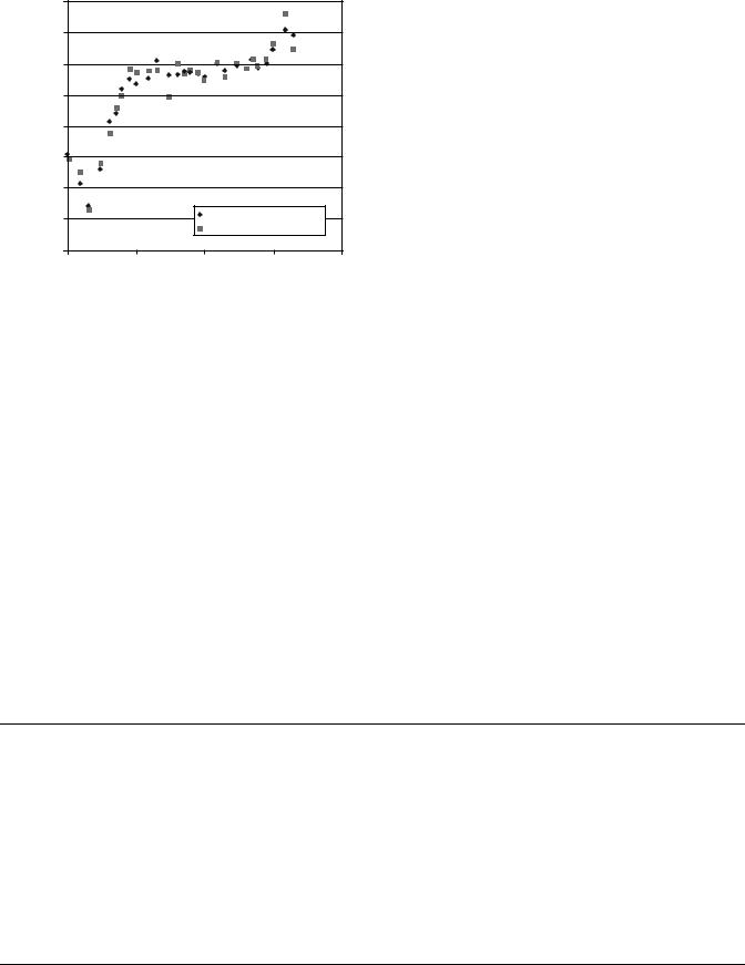
were obtained from an ICRU report (31). The book compiles photon, electron, proton, and neutron data for body tissues. The AP6 data were calculated using the atomic composition given in Table 3 and the photon interaction data compiled in a NIST report (45). Figure 1 shows an excellent agreement of the interaction parameter between two materials. Table 3 indicates that AP6 is Class A material of the adipose tissue for the entire photon energy range.
Several experiments were carried out to verify the accuracy with which the various substitutes simulate
260 |
PHANTOM MATERIALS IN RADIOLOGY |
|
|
|
|
|
|
|
|
|
||
Table 3. Classification of Tissue Substitute |
|
|
|
|
|
|
|
|
|
|||
|
|
|
|
|
|
|
|
|
|
|
|
|
|
|
|
|
|
|
|
Classification |
|
|
|
||
|
|
|
|
|
|
|
|
|
|
|
|
|
|
|
|
|
|
Photons |
Electrons |
|
Protons |
|
|
Neutrons |
|
|
|
|
|
|
|
|
|
|||||
|
|
|
|
|
|
|
|
|
|
|
|
|
Tissue being |
|
|
10–99 |
100 keV– |
10 keV– |
|
1–1000 |
|
1–99 |
100 keV– |
||
|
|
|
|
|||||||||
simulated |
Substitute |
Phase |
keV |
100 MeV |
100 MeV |
|
MeV |
|
keV |
30 MeV |
||
|
|
|
|
|
|
|
|
|
|
|
|
|
Adipose |
|
AP/SF1 |
Solid |
B |
A |
A (A) |
|
A |
|
A |
A |
|
tissue |
|
|
|
|
|
|
|
|
|
|
|
|
|
|
AP6 |
Solid |
A |
A |
A |
|
B |
|
C |
C |
|
|
|
AP/L2 |
Liquid |
C |
B |
A(B) |
|
A |
|
A |
A |
|
|
|
AP/RF1 |
Solid |
A |
|
|
|
|
|
|
|
|
Blood |
|
BL/L2 |
Liquid |
A |
A |
A (a) |
|
A |
|
A |
A |
|
Muscle |
|
A150 |
Solid |
C |
B |
B |
|
B |
|
A |
B |
|
|
|
Griffith |
Solid |
B |
B |
B |
|
B |
|
B |
B |
|
|
|
urethane |
|
|
|
|
|
|
|
|
|
|
|
|
MS/SR4 |
Solid |
C |
B |
B |
|
B |
|
A |
B |
|
|
|
MS20 |
Solid |
A |
A |
A |
|
B |
|
B |
B |
|
|
|
Figerio liquid |
Liquid |
A |
A |
A |
|
A |
|
A |
A |
|
|
|
MS/L1 |
Liquid |
A |
A |
A |
|
A |
|
A |
A |
|
|
|
Water |
Liquid |
A |
A(A ) |
A |
|
A |
|
B |
B |
|
|
|
MS/G1 |
Gel |
A |
A |
A |
|
A |
|
A |
A |
|
|
|
MS/G2 |
Gel |
A |
A |
A |
|
A |
|
A |
A |
|
|
|
MS/RM1 |
Solid |
A |
|
|
|
|
|
|
|
|
Cortical bone |
B110 |
Solid |
A |
A |
A |
|
B |
|
B |
B |
||
|
|
HB/SR4 |
Solid |
B |
A |
A |
|
B |
|
C |
C |
|
|
|
SB3 |
Solid |
A |
A |
A |
|
A |
|
C |
B |
|
|
|
Witt liquid |
Liquid |
A(B) |
A |
A |
|
A |
|
C |
C |
|
|
|
BTES |
Solid |
A |
A |
|
|
|
|
|
|
|
Inner bone |
IB/SR1 |
Solid |
B |
B |
B |
|
B |
|
A |
B |
||
|
|
IB7 |
Solid |
A |
B(A) |
A(B) |
|
A |
|
B |
C |
|
|
|
IB/L1 |
Liquid |
B |
A(B) |
A |
|
A |
|
A |
A |
|
Red marrow |
RM/SR4 |
Solid |
C |
B(A) |
A(B) |
|
A |
|
A |
A |
||
|
|
RM/L3 |
Liquid |
C |
B |
A(B) |
|
B |
|
A |
B |
|
|
|
RM/G1 |
Gel |
C |
B |
A(B) |
|
B |
|
A |
B |
|
Brain |
|
BRN/SR2 |
Solid |
C |
B |
B |
|
B |
|
A |
B |
|
|
|
BRN/L6 |
Liquid |
A |
A |
A |
|
A |
|
A |
A |
|
|
|
A181 |
Solid |
|
|
|
|
|
|
|
A |
A |
Kidney |
|
KD/L1 |
Liquid |
A |
A |
A |
|
A |
|
A |
A |
|
Liver |
|
LV/L1 |
Liquid |
A |
A |
A |
|
A |
|
A |
A |
|
Lung |
|
LN/SB4 |
Solid |
C |
B |
B |
|
B |
|
A |
B |
|
|
|
LN1 |
Solid |
A |
A |
A |
|
B |
|
C |
C |
|
|
|
LN10 |
Solid |
A |
B(A) |
A(B) |
|
B |
|
A |
B |
|
|
|
LTES |
Solid |
A |
A |
|
|
|
|
|
|
|
Thyroid |
|
TH/L2 |
Liquid |
A(B) |
A (B) |
A |
|
A |
|
A |
A |
|
Average breast |
BR12 |
Solid |
A |
A |
A |
|
B |
|
C |
C |
||
|
|
AV.BR/L2 |
Liquid |
A |
A |
A |
|
A |
|
A |
A |
|
Total soft tissue |
TST/L3 |
Liquid |
A |
A |
A |
|
A |
|
A |
A |
||
Total skeleton |
TSK/SF3 |
Solid |
A |
A |
A |
|
A |
|
A |
B |
||
|
|
TSK/L1 |
Liquid |
B |
A (B) |
A (B) |
|
A |
|
B |
B |
|
the corresponding real tissues. In one such series of experiments, thin-walled cells with 10 10 cm2 cross section were filled with real tissues and immersed in to appropriate tissue equivalent liquid to displace equal volume of that liquid. Central axis depth doses and beam profiles were then measured in the liquid behind the cells and the results compared with those obtained in the liquid alone. The material used or the construction of the cells was solid muscle substitute for the comparison with human muscle, beef stake, and pork, Brain substitute was used for the comparison with human brain. Co-60 g source was used for the irradiation experiments. In no case did the readings at
the depth differ by > 1% in each comparison. Similar tests were made with a 160 MeV synchrocyclotron proton beam and a neutron beam with average energy of 7.5 MeV (14,46). The results with the substitutes in place were generally within 0.5% of the readings for real tissues. In another series of tests, the relationship between the attenuation coefficients and the Hounsfield units measured with a computed tomography (CT) scanner was established first using 120 kVp X rays, and then the CT numbers were measured for a range of the new tissue substitutes. The attenuation coefficients derived from the measured CT number of each material was compared
|
|
|
|
|
|
|
|
|
PHANTOM MATERIALS IN RADIOLOGY |
261 |
|||
Table 4. Elemental Compositions of the Tissue Substitute |
|
|
|
|
|
|
|
||||||
|
|
|
|
|
|
|
|
|
|
||||
|
|
|
|
|
|
Elemental Composition (percentage by weight) |
|
|
|
||||
|
|
|
|
|
|
|
|
|
|
|
|
|
|
|
|
|
|
|
|
|
|
|
|
|
|
|
Other |
Tissue Substitutes |
|
H |
C |
N |
O |
Na |
Mg |
P |
S |
Cl |
K |
Ca |
Elements |
|
|
|
|
|
|
|
|
|
|
|
|
|
|
Adipose tissue |
|
|
|
|
|
|
|
|
|
|
|
|
|
AP/SF1 |
11.96 |
75.50 |
0.80 |
11.11 |
0.05 |
|
0.02 |
0.07 |
0.45 |
0.03 |
0.02 |
|
|
AP6 |
8.36 |
69.14 |
2.36 |
16.94 |
|
|
|
|
0.14 |
|
|
F(3.07) |
|
AP/L2 |
12.12 |
29.29 |
0.80 |
57.40 |
0.05 |
0.002 |
0.18 |
|
0.12 |
0.08 |
0.002 |
|
|
AP/RF1 |
14.11 |
84.07 |
|
0.92 |
|
0.30 |
|
|
|
|
0.60 |
|
|
Blood |
|
|
|
|
|
|
|
|
|
|
|
|
|
BL/L2 |
10.01 |
9.82 |
2.91 |
76.37 |
0.18 |
0.002 |
|
0.20 |
0.27 |
0.14 |
0.004 |
|
|
Muscle |
|
|
|
|
|
|
|
|
|
|
|
|
|
A150 |
10.10 |
77.60 |
3.50 |
5.20 |
|
|
|
|
|
|
1.80 |
F(1.70) |
|
Griffith urethane |
9.00 |
60.20 |
2.80 |
26.60 |
|
|
|
|
|
|
1.72 |
Sn(0.01) |
|
MS/SR4 |
9.50 |
70.28 |
3.48 |
15.55 |
0.08/ |
0.02 |
0.18 |
0.50 |
0.12 |
0.30 |
0.01 |
|
|
MS20 |
8.12 |
58.35 |
1.78 |
18.64 |
|
13.03 |
|
|
0.09 |
0.39 |
0.01 |
|
|
Figerio liquid |
10.20 |
12.30 |
3.50 |
72.89 |
0.07 |
0.02 |
0.20 |
0.32 |
0.08 |
0.39 |
0.01 |
|
|
MS/L1 |
10.20 |
12.30 |
3.50 |
72.90 |
0.07 |
0.02 |
0.20 |
0.32 |
0.09 |
0.39 |
0.01 |
|
|
Water |
11.19 |
|
|
88.81 |
|
|
|
|
|
|
|
|
|
MS/G1 |
10.20 |
12.51 |
3.50 |
73.00 |
0.07 |
0.02 |
0.20 |
|
0.09 |
0.39 |
0.01 |
|
|
MS/G2 |
10.35 |
12.31 |
3.50 |
73.04 |
0.07 |
0.02 |
0.20 |
|
0.09 |
0.39 |
0.01 |
|
|
MS/RM1 |
12.24 |
73.36 |
|
6.37 |
|
6.03 |
|
|
|
|
2.00 |
|
|
Cortical bone |
|
|
|
|
|
|
|
|
|
|
|
|
|
B110 |
3.70 |
37.10 |
3.20 |
4.80 |
|
|
|
|
|
|
26.29 |
F(24.39) |
|
HB/SR4 |
4.45 |
29.09 |
3.88 |
31.93 |
0.06 |
0.21 |
10.00 |
0.32 |
0.06 |
|
19.99 |
|
|
SB3 |
3.10 |
31.26 |
0.99 |
37.57 |
|
|
|
|
0.05 |
|
27.03 |
|
|
Witt liquid |
4.70 |
|
|
56.80 |
|
|
10.90 |
|
|
27.90 |
|
|
|
BTES |
4.0 |
37.8 |
1.5 |
35.3 |
|
|
|
|
0.1 |
|
9.4 |
Si(11.9) |
|
Inner bone |
|
|
|
|
|
|
|
|
|
|
|
|
|
IB/SR1 |
8.73 |
63.19 |
2.36 |
17.83 |
0.06 |
|
2.62 |
|
0.12 |
|
5.09 |
|
|
IB7 |
6.86 |
59.01 |
2.08 |
24.12 |
|
|
|
|
0.12 |
|
7.81 |
|
|
IB/L1 |
8.65 |
17.27 |
2.58 |
60.83 |
0.06 |
|
2.49 |
|
|
4.99 |
|
|
|
Red marrow |
|
|
|
|
|
|
|
|
|
|
|
|
|
RM/SR4 |
10.08 |
73.57 |
2.16 |
13.77 |
0.01 |
0.003 |
0.03 |
0.14 |
0.11 |
0.15 |
|
|
|
RM/L3 |
10.17 |
12.77 |
2.22 |
74.24 |
0.08 |
|
0.03 |
0.15 |
0.17 |
0.17 |
|
|
|
RM/G1 |
10.20 |
9.38 |
2.36 |
78.18 |
0.08 |
|
0.03 |
0.15 |
0.17 |
0.17 |
|
|
|
Brain |
|
|
|
|
|
|
|
|
|
|
|
|
|
BRN/SR2 |
10.69 |
72.33 |
1.28 |
14.59 |
0.18 |
0.01 |
0.36 |
|
0.06 |
0.30 |
0.01 |
|
|
BRN/L6 |
10.68 |
15.14 |
1.29 |
71.67 |
0.18 |
|
0.34 |
0.17 |
0.23 |
0.30 |
|
|
|
A181 |
10.7 |
80.3 |
2.2 |
3.3 |
|
|
|
|
|
|
1.8 |
F(1.7) |
|
Kidney |
|
|
|
|
|
|
|
|
|
|
|
|
|
KD/L1 |
10.40 |
11.35 |
2.74 |
74.50 |
0.18 |
|
0.19 |
|
0.28 |
0.25 |
|
|
|
Liver |
|
|
|
|
|
|
|
|
|
|
|
|
|
LV/L1 |
10.18 |
14.40 |
2.83 |
71.80 |
0.11 |
|
|
0.24 |
0.18 |
0.29 |
|
|
|
Lung |
|
|
|
|
|
|
|
|
|
|
|
|
|
LN/SB4 |
9.70 |
70.26 |
2.80 |
16.30 |
0.17 |
0.01 |
0.12 |
0.22 |
0.11 |
0.19 |
0.01 |
Si(0.50) |
|
LN1 |
6.00 |
51.44 |
4.29 |
30.72 |
|
|
|
|
|
|
|
Al(7.55) |
|
LN10 |
8.38 |
60.40 |
1.68 |
17.28 |
|
11.4 |
|
|
0.15 |
|
|
Si(0.84) |
|
LTES |
7.0 |
57.4 |
2.1 |
22.4 |
|
9.3 |
1.7 |
|
|
9.1 |
|
|
|
Thyroid |
|
|
|
|
|
|
|
|
|
|
|
|
|
TH/L2 |
10.01 |
13.58 |
2.20 |
73.52 |
0.22 |
|
0.08 |
|
0.14 |
0.19 |
|
I(0.06) |
|
Average Breast |
|
|
|
|
|
|
|
|
|
|
|
|
|
BR12 |
8.68 |
69.95 |
2.37 |
17.91 |
|
|
|
|
0.14 |
|
0.95 |
|
|
AV.BR/L2 |
11.79 |
37.86 |
|
50.41 |
|
|
|
|
|
|
|
|
|
Total soft tissue |
|
|
|
|
|
|
|
|
|
|
|
|
|
TST/L3 |
10.46 |
23.33 |
2.59 |
62.54 |
0.11 |
0.01 |
0.13 |
0.20 |
0.13 |
0.20 |
0.02 |
|
|
Total skeleton |
|
|
|
|
|
|
|
|
|
|
|
|
|
TSK/SF3 |
7.16 |
45.50 |
3.08 |
26.12 |
0.31 |
0.12 |
7.02 |
0.16 |
0.47 |
0.15 |
10.03 |
|
|
TSK/L1 |
7.45 |
4.64 |
2.94 |
66.93 |
0.32 |
|
7.00 |
|
0.13 |
10.15 |
|
|
|
|
|
|
|
|
|
|
|
|
|
|
|
|
|

262 PHANTOM MATERIALS IN RADIOLOGY
|
1.00E+01 |
|
|
|
|
|
|
|
|
|
|
|
|
|
|
|
|
|
|
|
|
|
|
|
|
|
|
|
|
|
|
|
|
|
|
|
|
|
Adipose adult |
|
|
|
|
|
|
|
|
|
|
|
|
|
||
|
|
|
|
|
|
AP6 |
|
|
|
|
[cm^2/g] |
1.00E+00 |
|
|
|
|
|
|
|
|
|
coefficient |
|
|
|
|
|
|
|
|
|
|
|
|
|
|
|
|
|
|
|
|
|
Mass attenuation |
1.00E–01 |
|
|
|
|
|
|
|
|
|
|
|
|
|
|
|
|
|
|
||
|
|
|
|
|
|
|
|
|
|
|
|
1.00E–02 |
|
|
|
|
|
|
|
|
|
|
|
|
|
|
|
|
|
|
|
|
|
0.01 |
0.10 |
1.00 |
10.00 |
||||||
Photon energy [MeV]
Figure 1. Comparison of mass attenuation coefficient for adult adipose tissue and tissue-mimicking material AP6.
to the calculated m value of each material. The measured m values were generally within 2% of the computed ones (14).
APPLICATIONS: RADIATION DOSIMETRY
Radiation exposure is equal to the number of electric charges liberated by interaction of photons with air. The gold standard for exposure measurement is a free-air chamber. The chamber size must be large enough to stop photons and associated secondary electrons. Since the size could be very large for practical uses, physicists developed small cylindrical chambers called thimble chambers by making the chamber wall with air-equivalent material (47–49). Graphite, Bakelite (C43H38O7), or mixture of those is commonly used as the wall material. These have a smaller effective atomic number than that of air; but, it is accepted because the central electrode of the ionization chamber is usually made of aluminum, whose atomic number, 13, is much larger than air (or 7.67).
Radiation dose absorbed in tissue is the most important physical parameter for therapeutic applications of radiation. It can cause fatal effects on a person or may fail to kill the malignant cells of a patient unless the delivered dose is carefully monitored. The mail instrument for dose measurement is the ionization chamber. The most common ionization chambers for dose measurement are cylindrical with an outer diameter of 1 cm and a length of air cavity of 2 cm. When the ionization chamber is used in a solid phantom or water, some corrections are needed to estimate the dose in the medium because of differences in materials of air, the chamber wall, and the phantom material (50).
Absorbed dose in real patients can be measured by placing radiation detectors on or inside the patient during treatment. Thermoluminescent detector (TLD), a solidstate detector, is a well-established instrument for the in
vivo dose measurements. The TLD is made of thermoluminescent material, which absorbs radiation energy. The electric charges created in the material can be measured by heating the chip after irradiation and used to estimate the absorbed dose. In addition to the thermoluminescent characteristics, TLD should be radiologically equivalent to tissue. The common TLD material is lithium fluoride (LiF) with some impurities such as Magnesium (Mg) or Titanium (Ti) to improve the property. The effective atomic number is kept close to the tissue, or 8.2, for LiF TLD to minimize the fluence disturbance due to a foreign material placed in tissue. Since the TLD material is not identical to tissue, the response to radiation is different for that of tissue. A great concern exists when absorbed dose for low energy photons, or energies < 100 keV, must be measured because the radiation response is very different from the tissue in this energy range (47).
APPLICATIONS: RADIATION THERAPY
Accurate prediction of radiation dose delivered to patients is the most important step to generate effective radiotherapy treatment strategies. Medical physicists, who are responsible for physical aspects of the treatment planning, have to establish the physical data necessary for radiotherapy before anyone can be treated and even during actual treatment. For given radiation sources, medical physicists have to know how much radiation energy or dose is absorbed at any point in the patient’s body. Generally, computers are used to predict the dose distribution. The computer can calculate doses using radiation source specific physical data incorporated in the software. The necessary data vary according to the calculation model used by the computer program. In general the absolute dose at any point or at any depth in the human body and the relative dose in the entire body are needed.
Medical physicists have developed many physics concepts since radiation sources were introduced into the clinic. For radiotherapy using electron accelerators, medical physicists introduced three important concepts: output factor, depth dose, and beam profile (48,49). The output factor is the radiation dose at a specific depth along the central beam axis or at a reference point for a given standard field size, (e.g., 10 10 cm). The depth dose gives the dose to a point at a given depth as a fraction of the dose at the reference point along the central beam axis. The beam profile shows the variation of dose along a line on a plane perpendicular to the central beam axis.
Physical models of the radiation source and human body are not perfect. Dose calculations in a real human body are difficult because of the variation in shape and tissue densities. Consequently, necessary data must be measured. The measurements are generally performed in a uniform and large medium, such as a water phantom.
Tissue Equivalent Phantom
Water. Water is a favorite medium for dose measurements for several reasons. Water is nearly tissue equivalent and inexpensive (or readily available). Furthermore, a radiation detector can be scanned through in water for dose
|
|
1.020 |
|
|
|
|
|
|
1.015 |
|
|
|
|
|
water muscle or adipose |
1.010 |
|
|
|
|
Attenuation coefficient |
1.005 |
|
|
|
|
|
1.000 |
|
|
|
|
||
0.995 |
|
|
|
|
||
0.990 |
|
|
|
|
||
|
|
|
|
|
|
|
|
|
0.985 |
|
water vs muscle |
|
|
|
|
|
water vs adipose tissue |
|
||
|
|
|
|
|
||
|
|
0.980 |
|
|
|
|
|
|
0.010 |
0.100 |
1.000 |
10.000 |
100.000 |
Photon energy [MeV]
Figure 2. The ratio of mass attenuation coefficients between water and muscle or adipose tissue versus photon energy.
measurements at points spaced very closely. One should remember, however, that the equivalence of water to tissue depends on the photon energy and the tissue to which water is compared. Mass attenuation coefficients of water, muscle, and adipose tissue were evaluated for photons in the energy range between 1 keV and 20 MeV. The ratios of water to muscle and water to adipose tissue are plotted in Fig. 2. The mass attenuation coefficients of water are 1 % larger than those of muscle and adipose tissue for energies > 0.1 MeV. However, in the energy range between 0.01 and 0.1 MeV the mass attenuation coefficients of water are smaller as much as 1.5% with those of muscle and adipose tissue.
Solid Phantom. Liquid water is cumbersome to use in a high electric voltage environment such as in an accelerator room. Hence, medical physicists manufactured waterequivalent solid phantoms. There are a few solid phantom materials currently available commercially. The list of products is given in Table 5. Poly (methyl methacrylate)
PHANTOM MATERIALS IN RADIOLOGY |
263 |
or acrylic is sold under names of Lucite, Plexiglas, or Perspex. Polystyrene has usually clear color and it is common phantom material for physics quality assurance programs because of relatively low price. Physicists discovered that PMMA and polystyrene leads to as much as 5% error when those are used for the absolute dose measurements of electron beams. Hence, an epoxy resin-based solid water material was developed as a substitute for water (16). It was made to simulate radiological characteristics of water more accurately than PMMA and polystyrene. Both mass attenuation coefficients and electron stopping powers of the solid water agree with those of water within 1% for the energy range between 10 keV and 100 MeV (51).
The new generation of solid water is being manufactured by Gammex-RMI (Middleton, WI). The phantoms are available in slabs of various sizes and thickness as seen in Fig. 3. Plastic Water was developed by CIRS (Computerized Imaging Reference Systems Inc., Norfolk, VA). It is a variation of the solid water. It is flexible. It was shown that measured outputs of electron beams in the Plastic Water agree with water within 0.5% for energy ranging from 4 to 20 MeV (52). Med-Tec, Inc. (Orange City, IA) is manufacturing what they call Virtual Water, which has the same chemical composition and density as solid water, but the manufacturing process is different. Hermann et al. developed polyethylene-based water-equivalent solid material (17). The material is manufactured by PTW (Freiburg, Germany) and it is sold as White Water or RW3. It contains titanium oxide as additive.
The dose at a depth (5 or 7 cm for photon beams and the depth of dose maximum for electron beams) in solid phantoms was measured with ionization chambers for various photon and electron energies. The results were compared with the dose measured in water. Figure 4 shows the ratio of measured doses in a solid phantom and water for plastic water (PW), white water (RW-3), solid water (SW-451 and SW-457), and virtual water (VW) (52,53). The horizontal axis of the figure indicates the photon energy. The larger the ionization ratio, the higher the photon energy. The beam energy ranges from Co-60 g ray (1.25 MeV) to 24 MV. The solid water and virtual water show the best agreement
Table 5. Elemental Compositions of Common Water-Equivalent Phantom Materials
|
|
|
|
Elemental Composition (percentage by mass) |
|
|
|
|||||||||
|
|
|
|
|
|
|
|
|
|
|
|
|
|
|
|
N, |
|
|
|
|
|
|
|
|
|
|
|
|
Other |
Mass Density, |
|
||
Tissue |
|
|
H |
B |
C |
N |
O |
Mg |
Al |
Cl |
Ca |
Elements |
kg m 3 |
Zeff |
e kg 1 1026 |
|
PMMAa |
Lucite, Plexiglas, |
8.0 |
|
60.0 |
|
32.0 |
|
|
|
|
|
|
1170 |
6.24 |
3.25 |
|
(Acrylic) |
Perspex |
|
|
|
|
|
|
|
|
|
|
|
|
|
|
|
Polystyrene |
|
7.7 |
|
92.3 |
|
|
|
|
|
|
|
|
1060 |
5.69 |
3.24 |
|
Solid water |
GAMMEX-RMI |
8.1 |
|
67.2 |
2.4 |
19.9 |
|
|
0.1 |
2.3 |
|
|
1042 |
8.06 |
3.34 |
|
457 |
|
|
|
|
|
|
|
|
|
|
|
|
|
|
|
|
Virtual water |
MEDTEC |
8.1 |
|
67.2 |
2.4 |
19.9 |
|
|
0.1 |
2.3 |
|
|
1070 |
8.06 |
3.48 |
|
Plastic water |
CIRS |
7.4 |
2.26 |
46.7 |
1.56 33.52 |
6.88 |
1.4 |
0.24 |
|
|
|
1030 |
7.92 |
3.336 |
||
White water |
PTW |
7.61 |
|
91.38 |
|
0.14 |
|
|
|
|
Ti(0.78) |
1045 |
5.71 |
3.383 |
||
RW3 |
|
|
|
|
|
|
|
|
|
|
|
|
|
|
|
|
Polymer gel |
MGS |
10.42 |
|
10.45 |
2.44 |
76.68 |
|
|
|
|
|
|
1050 |
7.37 |
3.49 |
|
Water |
|
11.19 |
|
|
|
88.81 |
|
|
|
|
|
|
1000 |
7.42 |
3.343 |
|
aPoly (methyl methacrylate ¼ PMMA.)
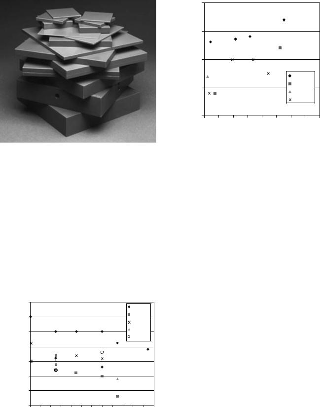
264 PHANTOM MATERIALS IN RADIOLOGY
Figure 3. Solid water phantom manufactured by GAMMEX-RMI (Middleton, WI).
among the evaluated materials. The results for electron beams are given in Fig. 5, where the horizontal axis indicates the effective energy, which is an approximation of the beam energy. The solid water and virtual water also show a good agreement for the entire electron energy.
Gel Phantom. A relatively new development is taking place on a tissue-equivalent material in gel form. The new material can record the radiation dose without additional instrument inserted in the phantom. The phantom can be made large enough to simulate the human body. Among many variations of gel phantoms, the most promising is polymer gel manufactured by MGS Research Inc. (Guilford, CT) (54). Originally it was made of acrylamide, N, N0- methylenebisacrylamide (bis), agarose, and water. The chemical composition was optimized over years. Currently,
|
|
1.015 |
|
|
|
|
|
|
|
|
|
PW |
|
|
|
|
|
|
|
|
|
|
|
|
|
|
|
|
|
|
|
1.01 |
|
|
|
|
|
|
|
|
|
RW3 |
|
|
|
|
|
|
|
|
|
|
|
|
|
SW457 |
|
||
|
|
|
|
|
|
|
|
|
|
|
|
|
||
|
|
1.005 |
|
|
|
|
|
|
|
|
|
SW451 |
|
|
The dose ratio |
|
|
|
|
|
|
|
|
|
|
|
|
|
|
Solid water |
|
|
|
|
|
|
|
|
|
|
VW |
|
|
|
1 |
|
|
|
|
|
|
|
|
|
|
|
|
||
0.995 |
|
|
|
|
|
|
|
|
|
|
|
|
||
|
|
|
|
|
|
|
|
|
|
|
|
|
||
|
|
0.99 |
|
|
|
|
|
|
|
|
|
|
|
|
|
|
0.985 |
|
|
|
|
|
|
|
|
|
|
|
|
|
|
0.98 |
|
|
|
|
|
|
|
|
|
|
|
|
|
|
1 |
3 |
5 |
7 |
9 |
11 |
13 |
15 |
17 |
19 |
21 |
23 |
25 |
|
|
|
|
|
|
|
Energy [MeV] |
|
|
|
|
|
||
Figure 4. The ratio of measured output in solid phantom and water for photon beams.
|
1.01 |
|
|
|
|
|
|
|
|
|
1 |
|
|
|
|
|
|
|
|
Solid/Water |
0.99 |
|
|
|
|
|
|
|
|
|
|
|
|
|
|
PW |
|
|
|
|
|
|
|
|
|
RW3 |
|
||
|
0.98 |
|
|
|
|
|
|
||
|
|
|
|
|
|
SW451 |
|
||
|
|
|
|
|
|
|
|
||
|
|
|
|
|
|
|
SW457 |
|
|
|
0.97 |
|
|
|
|
|
|
|
|
|
4 |
6 |
8 |
10 |
12 |
14 |
16 |
18 |
20 |
Effective energy. E0
Figure 5. The ratio of measured output in solid phantom and water for electron beams.
the polymer gel is sold as BANG3 with 80% water, 14% of gelatin, and 6% of methacrylic acid by mass. A typical atomic composition of the polymer gel as well as the mass density, the effective atomic number, and the electron density are given in Table 5. The effective atomic number and the electron density of the polymer gel agree with those of water very well. The polymer gel produces highly linked polymers when it is irradiated. The structural change causes a change in color and mass density. The recorded dose distribution can be indirectly read by measuring the photon attenuation of both visible light and X ray. The polymerization also causes a change in the magnetic property of the gel. The most popular method is currently to scan the irradiated phantom with a magnetic resonance imaging (MRI) scanner. It takes advantage of the change in the spin–spin relaxation rate, which increases with increasing absorbed dose.
Differing from more traditional dose measurement tools, polymer gel dosimeter enables medical physicists to obtain full three-dimensional (3D) dose distributions in a geometrically consistent way. Polymer gel phantom was used to measure 3D dose distributions of advanced radiotherapy treatment such as those for intensity modulated radiation therapy (IMRT) (55) and Gamma Knife stereotactic radiosurgery (56). Figure 6 shows an MRI image taken after the polymer gel was irradiated with a Gamma Knife system (Elekta AB, Stockholm, Sweden). The blighter color indicates higher dose.
Geometric Phantom
With the advent of rapid development of highly conformal radiation therapy, modern radiation therapy requires high geometrical precision of radiation delivery. At the same time, the complexity of treatment planning software has substantially increased. This has urged medical physicists to test the geometrical precision of the treatment planning software (57). Special phantoms are being manufactured to assure the quality of geometry created by the software.
PHANTOM MATERIALS IN RADIOLOGY |
265 |
Figure 6. Dose distribution images obtained by polymer gel dosimeter for Gamma Knife irradiation.
Here we discuss two of those phantoms currently on market.
Lucy 3D Precision Phantom. Lucy phantom was developed by Toronto Sunny Brook Regional Cancer Center and Sandstrom Trade and Technology, Inc. (Ontario, Canada) (58). The acrylic phantom of a shape of head (Fig. 7) is used to test the image quality of CT, MRI, and X ray imaging modalities, which are used for stereotactic radiation therapy. It can verify imaging errors, image distortions, and the geometrical accuracy of treatment planning system. It serves also as routine machine QA equipment.
Figure 7. Lucy 3D precision phantom from the Sandstrom Trade and Technology Inc. (Ontario, Canada).
Figure 8. Quasar beam geometry MLC phantom from Modus Medical Devices, Inc. (Ontario, Canada).
Quasar Phantom. Another Canadian company, Modus Medical Device, Inc. (Ontario, Canada), developed phantoms to verify geometrical accuracy generated by radiation therapy treatment planning software (59). The phantoms are made of Lucite, cedar, and polystyrene. One of those, Quasar body phantom, can be used to test the accuracy of the digitally reconstructed radiography (DRR) images. DRR images are generated from a number of axial images taken by a CT scanner and the DRR images are compared with the images taken with an electronic portal imaging system or with radiographic port films before treatment to verify the patient position accuracy. Quasar beam geometry MLC phantom shown in Fig. 8 can verify the geometrical display accuracy of leaf position and the size of the multileaf collimator, which have replaced traditional blocks to define radiation fields.
Humanoid Phantom
Complex high precision radiation delivery techniques, such as IMRT and stereotactic radiation therapy, demand ever increasing accuracy of dose delivery in geometry close to the human body. Body phantoms such as Rando and Alderson were introduced many years ago. Those were used to predict to radiation exposure to humans during radiation therapy and diagnostic radiology procedures. The Rando phantom manufactured by the Phantom Laboratory (Salem, NY) is shown in Fig. 9. The body phantom is sliced into many 5 cm thick slabs. Radiographic films can be inserted between the slabs for dose measurements. The slabs can also hold TLD chips for absolute dose measurements. The phantom is made of soft-tissue equivalent material, which is manufactured with proprietary urethane formulation. The phantom uses natural human skeletons. Lungs and breast closely mimic the real tissues.
Recently, many phantoms which simulate a part of body were developed, for example, Gammex-RMI, Phantom

266 PHANTOM MATERIALS IN RADIOLOGY
Figure 9. Rando phantom manufactured by the Phantom Laboratory (Salem, NY).
Laboratory, CIRS (60), and so on. Many of those phantoms are made to measure dose inside the phantom for verification of radiation therapy treatment. There are phantoms in various shapes for IMRT QA. Those phantoms can accommodate ionization chambers, radiographic films, and TLDs for dose measurements. Those may have special inserts for nonsoft tissue materials, such as lung and bone. The shapes of the phantoms are torso, head, thorax, pelvis, and neck.
DIAGNOSTIC IMAGING
X Rays
X rays are used to take images of parts of the body for diagnostic purposes (61). The oldest and most commonly used X ray imaging modality is X ray radiography. Images can be recorded on radiographic films. Recently, digital recording has become more common since the digital technique requires no wet-film processing and allows radiologists to manipulate and store the images more easily than hard-copy films.
Medical physicists use phantoms to test the quality of images. Some of common phantoms are dual-energy X ray absorptiometry phantom, anatomical phantoms (62), digital subtraction angiography (DSA) phantom, contrast detail phantom, and dental image QA phantoms.
Fluoroscopy
A regular X ray device can take static images of patients. A fluoroscopic unit, consisting of an X-ray tube, a camera, an image intensifier, and a TV monitor, can record images of moving parts of the body and of objects placed inside the body. This method of recording images is called fluoroscopy. Interventional radiologists use fluoroscopy to monitor the location of very thin wires and catheters going through blood vessels as those are being inserted during a procedure. Phantoms are an important instrument to assure the quality of fluoroscopy images. There are fluoro-
scopic phantoms, such as cardiovascular fluoroscopic benchmark phantom, fluoroscopy accreditation phantom, and test phantom.
Mammography
Mammography is a major diagnostic modality to detect breast cancer. The tumor size is often very small, that is, submillimeter diameter. Though small, early discovery of such small tumors is very important and can lead to better therapy outcomes, that is, higher cure rates and longer survival. Hence, the quality of X ray equipment used for mammography is a key for the success of this imaging modality and its performance is tightly controlled by federal and local governments. Consequently, medical physicists developed many phantoms to evaluate the imaging quality of mammography devices accurately and efficiently. Several phantoms are used, known as QA phantom, accreditation phantom, high contrast resolution phantom, contrast detail phantom, digital stereotactic breast biopsy accreditation phantom, phototimer consistency test tool, and collimator assessment test tool. A tissue-equivalent phantom manufactured by CIRS (Norfolk, VA) is shown in Fig. 10. The phantom is 4.5 cm thick and simulates the shape of a breast during the imaging. It is made of CIRS resin material mimicking the breast tissue. Objects with varying size within the phantom simulate calcifications, fibrous tissue in ducts, and tumor masses.
Computed Tomography
Computed tomography scanning systems were developed in the 1970s and rapidly deployed into clinics into the 1980s. Currently, this imaging modality is commonly used for diagnosis and radiation therapy in clinic and hospitals. Compute tomography provides patient’s anatomy on planes transverse to body axis (from head to toe). The plane images called axial slices are taken every 0.05–1 cm. Depending on the axial length of the scan, the number of slices can vary from 20 to 200. Computed tomography
Figure 10. Tissue-equivalent mammography phantom from CIRS (Norfolk, VA).

enables radiologists to visualize the location of disease in 3D, leading to potentially more accurate diagnosis. Medical physicists use phantoms to estimate dose to patients during CT scan, to test the precision of scanning geometry, and verify the quality of CT images. Such phantoms are the bone mineral analysis phantom, spiral/helical CT phantom, CT dose phantom, orthopedic calibration phantom, spine phantom, electron density phantom, and CT performance phantom.
Each picture element (pixel) of a CT image is represented by a CT number (or Hounsfield units). The CT number for water is 0, while the CT numbers in the lung are below -200 and those in the bones are 200. Since the CT number is found to depend on the electron density, among other parameters, it can be used to identify the material type and the distribution of the tissue inhomogeneities, which is very useful in radiation therapy treatment planning. One electron density phantom, developed in order to establish the relationship of CT number and tissue electron densities, is made of solid water and has cylindrical shape with a radial size of pelvis and 6 cm thickness. Small cylindrical inserts mimicking different tissues are plugged into the phantom. When it is CT scanned, the measured CT numbers of those materials can be plotted against the predetermined electron densities and the resulting data are used in treatment planning computer. This electron density CT phantom, which is now commercially available, shown in Fig. 11, was designed by Constantinou (63) and manufactured by GAMMEX-RMI (Middleton, WI). Available insert materials are lung (LN-300 and LN-450), adipose (AP6), breast, CT solid water, CB3 resin, brain, liver (LV1), inner bone, bone (B200, CB2-30% mineral, CB2-50% mineral), cortical bone (SB3), Titanium simulating Titanium implants for hip replacements, and true water.
Figure 11. Electron density phantom RMI 467 from GAMMEXRMI (Middleton, WI).
PHANTOM MATERIALS IN RADIOLOGY |
267 |
NUCLEAR MEDICINE
For nuclear medicine procedures, radioactive compound composed from Technetium, Iodine, Fluorine, etc. is injected into blood stream (64). The material is carried to a potential disease site by blood and stays there. Radioactive material emits photons or positively charged electrons called positrons. Since photons can easily escape the patient body, the photons can be detected by a photon detecting device. The photons are used to form images. Positron emission tomography (PET) uses positron emitting radioactive material. When a positron interacts with an electron in the body, both particles are converted into photons. The PET is more advanced nuclear medicine procedure and can generate 3D distributions of radioactive material. Phantoms are used for quality assurance of nuclear medicine systems. A NEMA (National Electrical Manufacturers Association) scatter phantom manufactured by CIRS Inc. (Norfolk, VA) is a circular polystyrene cylinder. Radioactive material with known activity is delivered to line source insert tubes. The image of the phantom is taken to test scatter fraction and count losses.
FUTURE
Tissue-equivalent materials for solid phantoms are well developed. There may be a need of incremental improvement in phantom materials possibly for lower price and more accurate representation of tissue types. Furthermore, phantom materials are needed for newer radiation types such as heavy ions. As new therapy and imaging modalities will be put into practice, new phantoms will be developed for efficient and accurate testing of those new tools. Modern radiology utilizes not only ionizing radiation such as photons, electrons, and heavy particles, but also electromagnetic radiation (or EM-waves) and ultrasound. Phantom materials exist for testing ultrasound devices and MRI scanners. This is an active area for development. For example, D’Souza recently developed a phantom used for quality testing of ultrasound, MRI, and CT (65). Readers interested in those phantoms should consult with the phantom manufactures, such as GAMMEX-RMI (Middleton, WI), CIRS, Inc. (Norfolk, VA) and Fluke/Cardinal Health (Cleveland, OH).
Here, the focus is on two aspects of interest for future development. It may be necessary to develop more biologically tissue equivalent phantom materials. Such materials simulate not only the radiological characteristics of radiation modalities, but also it can closely simulate the radiation effects on the tissues in realistic geometry. Biomedical engineers and scientists are vigorously working on artificial tissue, potentially replacing the real tissue. Such material could be also used as phantom material. Readers should refer to a comprehensive review on the current state of art in tissue engineering authored by Lanza et al. (66).
Computer modeling of human body is an active field of research and development. Noticeable example is the Visual Human Project sponsored by National Library of Medicine, NLM (67). Whole bodies of male and female cadavers were scanned with CT and MRI. The datasets
268 PHANTOM MATERIALS IN RADIOLOGY
are available for anyone who is interested in the information through licensing with NLM and with minimal cost. The datasets for the male consist of 12 bits axial MRI images of the head and neck and up to 1871 axial CT slices of the whole body. The female data set is 5000 axial CT images, with which one can reconstruct 3D images with 0.33 0.33 0.33 mm cubic voxels. The data can be used to construct human body model for quality assurance of radiological systems, in particular, for testing the radiation therapy treatment planning system. In addition to real geometry, the data contain the detailed information of tissue heterogeneities in human body. Such data are indispensable for accurate assessment of new radiological technologies.
BIBLIOGRAPHY
1.Spires FW. Materials for depth dose measurement. Br J Radiol 1943;16:90.
2.Kienbock R. On the quantimetric method. Arch Roentgen Ray 1906;1:17.
3.Baumeister L. Roentgen ray measurements. Acta Radiol 1923;2:418.
4.Ott P. Zur Rontgenstrahlenbehandlung oberblachlich gelagerter Tumoren. Strahlentherapie 1937;59:189.
5.Jones DEA, Raine HC. Bri J Radiol 1949;22.
6.Harris JH, et al. The development of a chest phantom for radiologic technology. Radiology 1956;67:805.
7.Markus B. The concept of tissue equivalence and several water-like phantom substances for energies of 10 KeV to 100 MeV as well as fast electrons. Strahlentherapie 1956; 101:111–131.
8.Rossi HH, Failla G. Tissue equivalent ionization chamber. Nucleonics 1956;14:32.
9.Shonka FR, Rose JE, Failla G. Conducting plastic equivalent to tissue, air and polystyrene. Prog Nucl Energy 1958;12:184.
10.Griffith RV, Anderson AL, Dean PN. Further realistic torso phantom development. University of California Research Laboratory, UCRL-50007-76-1; 1976.
11.Goodman LJ. A modified tissue equivalent liquid. Health Phys 1969;16:763.
12.Frigerio NA, Sampson MJ. Tissue equivalent phantoms for standard man and muscle. Argonne National Laboratory, Argonne, IL. ANL-7635; 1969.
13.White DR. The formulation of substitute materials with predetermined characteristics of radiation absorption and scattering. Ph.D. dissertation University of London, London; 1974.
14.Constantinou C. Tissue substitutes for particulate radiations and their use in radiation dosimetry and radiotherapy. Ph.D. dissertation, University of London, 1978.
15.White DR, Constantinou C. Prog Med Radiat Phys 1982;1:133.
16.Constantinou C, Attix FH, Paliwal BR. A solid water phantom material for radiotherapy x-ray and gamma-ray beam calibrations. Med Phys 1982;9:436–441.
17.Hermann KP, Geworski L, Muth M, Harder D. Polyethylenebased water-equivalent phantom material for x-ray dosimetry at tube voltages from 10 to 100 kV. Phys Med Biol 1985;30: 1195–1200.
18.Hermann KP, et al. Muscleand fat-equivalent polyethylenebased phantom materials for x-ray dosimetry at tube voltages below 100 kV. Phys Med Biol 1986;31:1041–1046.
19.Kalender WA, Suess C. A new calibration phantom for quantitative computed tomography. Med Phys 1987;14:863–886.
20.Homolka P, Nowotny R. Production of phantom materials using polymer powder sintering under vacuum. Phys Med Biol 2002;47:N47–52.
21.Homolka P, Gahleitner A, Prokop M, Nowotny R. Optimization of the composition of phantom materials for computed tomography. Phys Med Biol 2002;47:2907–2916.
22.Jones AK, Hintenlang DE, Bolch WE. Tissue-equivalent materials for construction of tomographic dosimetry phantoms in pediatric radiology. Med Phys 2003;30:2072–2081.
23.Suess C, Kalender WA, Coman JM. New low-contrast resolution phantoms for computed tomography. Med Phys 1999;26: 296–302.
24.Iwashita Y. Basic study of the measurement of bone mineral content of cortical and cancellous bone of the mandible by computed tomography. Dentomaxillofac Radiol. 2000;29:209– 215.
25.Burmeister J, et al. A conducting plastic simulating brain tissue. Med Phys 2000;27:2560–2564.
26.ICRU. Tissue substitutes in radiation dosimetry and measurement. International Commission on Radiological Units and Measurements, Bethesda, MD, ICRU Report 44; 1989.
27.Woodard HQ. The elementary composition of human cortical bone. Health Phys 1962;8:513–517.
28.ICRU. Physical Aspects of Irradiation. International Commission on Radiological Units and Measurements, Bethesda, MD, Report 10b; 1964.
29.ICRP. Reference man: anatomical, physiological and metabolic characteristics. International Commission on Radiological Protection, Stockholm, Sweden, ICRP Publication 23; 1975.
30.Constantinou C. Phantom materials for radiation dosimetry. I. Liquids and gels. Br J Radiol, 1982;55:217–224.
31.ICRU. Photon, electron, proton and neutron interaction data for body tissues, International Commission on Radiological Units and Measurements, Bethesda, (MD): ICRU Report 46; 1992.
32.White DR, Fitzgerald M. Calculated attenuation and energy absorption coefficients for ICRP Reference Man (1975) organs and tissues. Health Phys 1977;33:73–81.
33.Bewley DK. Pre-therapeutic experiments with the fast neutron beam from the Medical Research Council cyclotron. II. Physical aspects of the fast neutron beam. Br J Radiol 1963; 36:81–88.
34.Jones TD. Distributions for the design of dosimetric experiments in a tissue equivalent medium. Health Phys 1974;27: 87–96.
35.White DR. Phantom materials for photons and electrons. Hospital Physicists Association, London, S. Rep. Ser. No. 20; 1977.
36.Frigerio NA, Coley RF, Sampson MJ. Depth dose determinations. I. Tissue-equivalent liquids for standard man and muscle. Phys Med Biol 1972;17:792–802.
37.Frigerio NA. Neutron penetration during neutron capture therapy. Phys Med Biol 1962;6:541–549.
38.White DR. The formulation of tissue substitute materials using basic interaction data. Phys Med Biol 1977;22:889–899.
39.White DR. An analysis of the Z-dependence of photon and electron interactions. Phys Med Biol 1977;22:219–228.
40.Geske G. The concept of effective density of phantom materials for electron dosimetry and a simple method of their measurement. Radiobiol Radiother 1975;16:671–676.
41.White DR, Martin RJ, Darlison R. Epoxy resin based tissue substitutes. Br J Radiol 1977;50:814–821.
42.White DR. Tissue substitutes in experimental radiation physics. Med Phys 1978;5:467–479.
43.White DR, Constantinou C, Martin RJ. Foamed epoxy resinbased lung substitutes. Br J Radiol 1986;59:787–790.