

- •VOLUME 5
- •CONTRIBUTOR LIST
- •PREFACE
- •LIST OF ARTICLES
- •ABBREVIATIONS AND ACRONYMS
- •CONVERSION FACTORS AND UNIT SYMBOLS
- •NANOPARTICLES
- •NEONATAL MONITORING
- •NERVE CONDUCTION STUDIES.
- •NEUROLOGICAL MONITORS
- •NEUROMUSCULAR STIMULATION.
- •NEUTRON ACTIVATION ANALYSIS
- •NEUTRON BEAM THERAPY
- •NEUROSTIMULATION.
- •NONIONIZING RADIATION, BIOLOGICAL EFFECTS OF
- •NUCLEAR MAGNETIC RESONANCE SPECTROSCOPY
- •NUCLEAR MEDICINE INSTRUMENTATION
- •NUCLEAR MEDICINE, COMPUTERS IN
- •NUTRITION, PARENTERAL
- •NYSTAGMOGRAPHY.
- •OCULAR FUNDUS REFLECTOMETRY
- •OCULAR MOTILITY RECORDING AND NYSTAGMUS
- •OCULOGRAPHY.
- •OFFICE AUTOMATION SYSTEMS
- •OPTICAL FIBERS IN MEDICINE.
- •OPTICAL SENSORS
- •OPTICAL TWEEZERS
- •ORAL CONTRACEPTIVES.
- •ORTHOPEDIC DEVICES MATERIALS AND DESIGN OF
- •ORTHOPEDICS PROSTHESIS FIXATION FOR
- •ORTHOTICS.
- •OSTEOPOROSIS.
- •OVULATION, DETECTION OF.
- •OXYGEN ANALYZERS
- •OXYGEN SENSORS
- •OXYGEN TOXICITY.
- •PACEMAKERS
- •PAIN SYNDROMES.
- •PANCREAS, ARTIFICIAL
- •PARENTERAL NUTRITION.
- •PERINATAL MONITORING.
- •PERIPHERAL VASCULAR NONINVASIVE MEASUREMENTS
- •PET SCAN.
- •PHANTOM MATERIALS IN RADIOLOGY
- •PHARMACOKINETICS AND PHARMACODYNAMICS
- •PHONOCARDIOGRAPHY
- •PHOTOTHERAPY.
- •PHOTOGRAPHY, MEDICAL
- •PHYSIOLOGICAL SYSTEMS MODELING
- •PICTURE ARCHIVING AND COMMUNICATION SYSTEMS
- •PIEZOELECTRIC SENSORS
- •PLETHYSMOGRAPHY.
- •PNEUMATIC ANTISHOCK GARMENT.
- •PNEUMOTACHOMETERS
- •POLYMERASE CHAIN REACTION
- •POLYMERIC MATERIALS
- •POLYMERS.
- •PRODUCT LIABILITY.
- •PROSTHESES, VISUAL.
- •PROSTHESIS FIXATION, ORTHOPEDIC.
- •POROUS MATERIALS FOR BIOLOGICAL APPLICATIONS
- •POSITRON EMISSION TOMOGRAPHY
- •PROSTATE SEED IMPLANTS
- •PTCA.
- •PULMONARY MECHANICS.
- •PULMONARY PHYSIOLOGY
- •PUMPS, INFUSION.
- •QUALITY CONTROL, X-RAY.
- •QUALITY-OF-LIFE MEASURES, CLINICAL SIGNIFICANCE OF
- •RADIATION DETECTORS.
- •RADIATION DOSIMETRY FOR ONCOLOGY
- •RADIATION DOSIMETRY, THREE-DIMENSIONAL
- •RADIATION, EFFECTS OF.
- •RADIATION PROTECTION INSTRUMENTATION
- •RADIATION THERAPY, INTENSITY MODULATED
- •RADIATION THERAPY SIMULATOR
- •RADIATION THERAPY TREATMENT PLANNING, MONTE CARLO CALCULATIONS IN
- •RADIATION THERAPY, QUALITY ASSURANCE IN
- •RADIATION, ULTRAVIOLET.
- •RADIOACTIVE DECAY.
- •RADIOACTIVE SEED IMPLANTATION.
- •RADIOIMMUNODETECTION.
- •RADIOISOTOPE IMAGING EQUIPMENT.
- •RADIOLOGY INFORMATION SYSTEMS
- •RADIOLOGY, PHANTOM MATERIALS.
- •RADIOMETRY.
- •RADIONUCLIDE PRODUCTION AND RADIOACTIVE DECAY
- •RADIOPHARMACEUTICAL DOSIMETRY
- •RADIOSURGERY, STEREOTACTIC
- •RADIOTHERAPY ACCESSORIES

33.Ebersole RC, Ward MD. Amplified mass immunosorbent assay with a quartz crystal microbalance. J Am Chem Soc 1988;110: 8623–8628.
34.Su X, Li SFY, O’Shea SJ. Au nanoparticleand silverenhancement reaction-amplified microgravimetric biosensor. Chem Commun 2001; 755–756.
35.Fawcett NC, Evans JA, Chen LC, Drozda KA, Flowers N. A quartz crystal detector for DNA. Anal Lett 1988;21:1099–1110.
36.Su X, Robelek R, Wu Y, Wang G, Knoll W. Detection of point mutation and insertion mutations in DNA using a quartz crystal microbalance and MutS, a mismatch binding protein. Anal Chem 2004;76:489–494.
37.Liu T, Tang J, Jiang L. The enhancement effect of gold nanoparticles as a surface modifier on DNA sensor sensitivity. Biochem Biophys Res Commun 2004;313:3–7.
38.Mao X, Yang L, Su X-L, Li Y. A nanoparticle-based quartz crystal microbalance DNA sensor for the detection of Escherichia coli O157:H7. Biosens Bioelectron. In press.
See also COCHLEAR PROSTHESES.
PLETHYSMOGRAPHY. See IMPEDANCE
PLETHYSMOGRAPHY.
PNEUMATIC ANTISHOCK GARMENT. See
SHOCK, TREATMENT OF.
PNEUMOTACHOMETERS
NARCISO F. MACIA
Arizona State University at the
Polytechnic Campus Mesa,
Arizona
INTRODUCTION
From the beginning of time, breathing has been important since it has been the most common indicator of life. The Bible indicates that God infused life into man by ‘‘blowing into his nostrils the breath of life’’ (1). Not surprisingly then, the way in which we breath is an important indicator of our health. Consequently, the medical profession has tried to learn our physical condition by focusing on the behavior of the respiratory system. Two main mechanisms take place in the breathing process: (1) Movement of gases from the nose and mouth to the alveoli, and (2) CO2 and O2 gas exchange at the alveoli. An interesting historical perspective, standardization of pulmonary function tests (PFTs) and the associated equipment received a great push from the mobile PFT trucks that were part of a campaign to eliminate lung cancer in the United States in the 1950s. Even today, PFTs are often used as a preliminary screen for lung cancer.
This section focuses on the equipment used to make flow and volume measurements in the first category: pneumotachometers, also known as respirometers, spirometers, or simply flowmeters.
There are two clinical areas where flow measurement devices are used. These are (1) the field of spirometry (2–4), dealing with the actual performance of the respiratory system as reflected by the volumes that the lung can
PNEUMOTACHOMETERS 367
realize, and the speed in which these volumes can be moved in and out of the lungs. Indicators such as tidal volume (TV or Vt) and vital capacity (VC) provide a glimpse of the range of motion of the lungs. Similarly, parameters, such as FEV1 (forced expiratory volume in 1 s) and FEF25–75% (forced expiratory flow at the mid-portion of forced vital capacity). Notice that these parameters are the result of: (a) the patient’s ability to cooperate, (b) condition of the diaphragm, the respiratory system’s main workhorse, (c) range of motion of the lungs, and (d) the mechanical components associated with the respiratory pathways (size of the conducting airways). (2) The field of parameter estimation (5–12), dealing specifically with the noninvasive measurement of components descriptive of the mechanical characteristics of the respiratory apparatus. These parameters include resistance, compliance, and inertance. One advantage of this approach is its independence from the patient’s ability to cooperate. This approach is particularly useful in unconscious, and very young or very old patient populations. However, this approach requires a much higher level of computation.
Before proceeding with a presentation on pneumotachometer, some definitions and conventions are appropriate.
Open and Closed Systems
In many pulmonary function tests, the test procedure requires that the subject inhales maximally, then place the pneumotachometer in then mouth, and then exhales as fast as possible. This type of set up is referred to as an ‘‘open’’ system since no exhaled air is rebreathed. In other types of pulmonary function testing, the patient exchanges air back and forth with a reservoir. This later system is referred to as a ‘‘closed’’ system.
Variable Used for Flow
The most common variable used to describe flow is _ . The
V
‘‘dot’’ comes from the mathematical notation of differentiation with respect to time, originally developed by Sir Isaac Newton, or
˙ dV V ¼ dt
which implies that flow, V_ , is the time rate or change of lung volume, V.
Polarity
Spirometer tests consider expiratory flow as positive while parameter estimation procedures look at inspiration as positive. Perhaps it is reflective that most spirometer tests are performed during expiration while in parameter estimation procedures, inspiration is the primary arena.
DEVICES FOR MEASURING RESPIRATORY FLOW
This section presents devices that have and continue to be used for measuring respiratory flow and volume. Even though some of them are not used as often, they are part of the toolbox that clinicians and researchers have used in getting a handle in the respiratory system.
368 PNEUMOTACHOMETERS
Volume Displacement Type
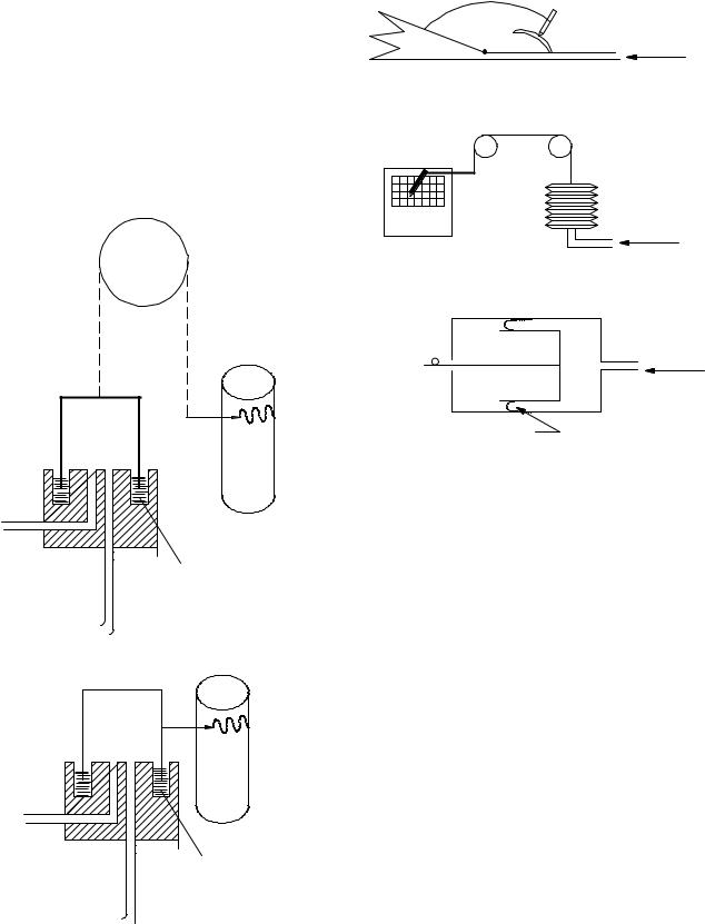
This type of device, often called volumetric type, captures the volume of gas coming out of the subject’s mouth with an expanding reservoir whose degree of expansion can be recorded either mechanically or electronically. Flow can be obtained by differentiating the changing volume. This type of instrument is still used in many pulmonary function facilities and exercise physiology laboratories, since they offer the highest accuracy available. There two types that use a water seal: (1) the counterbalanced bell and (2) the lightweight bell over a water seal (often called the Stead–Wells spirometer after the individuals who requested the device. These are shown in Fig. 1. Even
Pen
Rotating drum
Water seal
(a) Counterbalanced bell
Pen
Rotating drum
Water
(b) Lightweight bell (stead-wells)
Figure 1. Water seal spirometer.
Wedge-type |
Pen |
bellows |
|
|
Graph |
|
Flow from |
|
patient |
|
(a) Wedge type |
Bellows
Flow from
patient
(b) Bellows type
Electric potentiometer
Piston |
Flow from |
|
patient |
Rolling diaphragm
(c) Rolling diaphragm type
Figure 2. Non-water seal spirometers: (a) wedge type, (b) the bellows, and the (c) rolling diaphragm.
though these devices have served the medical community well, their bulkiness and expense have motivated biomedical equipment developers to design smaller, more portable nonvolumetric units, even though they are not as accurate as the volumetric type. Three other variations of the volume displacement type exist: the wedge type, the bellows, and the rolling diaphragm, as shown in Fig. 2 (13).
Other Applications of Volume Displacement Type. The water seal spirometers have also been used to monitor breathing over longer periods of time. Simply closing the circuit creates some problems since O2 in the air is being consumed while and the mixture becomes progressively CO2 rich. To solve this problem, the bell is originally filled with O2, and a CO2 scrubber (Baralyme, a trade name for generic BaO) is inserted into the circuit. After a few seconds, additional oxygen is inserted into the circuit. The setup and the resulting the waveform are shown in Fig. 3. This device has found applications to evaluate the metabolic rate (proportional to O2 consumption).
This device has also been used to measure compliance, the elasticity of the respiratory system (RS). It is carried out by adding a series of weights on top of the spirometer bell, which increases the overall system pressure (14,15). The corresponding change in system volume
|
CO2 absorber |
|
|
Straps |
Nose |
Bell |
Pen |
|
|||
|
|
|
|
|
clip |
|
|
Water
Rotating
canometer
check Water drum calves
Foam pad
Time  bell inside Volume
Figure 3. Closed-circuit spirometer.
detected at the bell, which corresponds to the increase in lung volume, is measured. The resulting respiratory compliance is given by
DV
CRS ¼ DP
This approach has been automated by Crawford (16). Notice that the resulting compliance, the compliance of the respiratory system, CRS, captures both the compliance of the lungs, CL, and the compliance of the chest wall CCW:
1 ¼ 1 þ 1
CRS CL CCW
and the lung compliance is made up of the compliance of the left and right lobes.
CL ¼ CL left þ CL right
The following type of pneumotachometers measure flow directly, instead of measuring change in volume. These devices electronically integrate the flow signal to obtain volume.
FLUID RESISTANCE TYPE OF PNEUMOTACHOMETERS
Fleish Pneumotachometers
Another device that has been and continues to be used extensively is the Fleish (or Fleisch) pneumotachometer (17). It consists of a fluid resistive device through which the air passes. The pressure drop across a fluid resistive element created by the respiratory flow is applied to a pressure transducer. Since there is a linear correlation between the measured pressure drop and flow, flow can be determined from the pressure drop. This approach has also been the primary workhorse of pulmonary instrumentation. There are two areas of concern with this type of device:
(1) the linearity of the correlation between pressure drop and volumetric flow, and (2) the potential condensation of vapor droplets in the resistive element. Both of these factors can affect the device’s accuracy. The American Thoracic Society (ATS), the medical section of the American Lung Association (18), has published standards regarding the required accuracy of the equipment (5% in
PNEUMOTACHOMETERS 369
some tests, while 3% in others) They have also established the conditions in which the results should be reported: BTPS. [BTPS stands for body conditions: normal body temperature (37 8C) ambient pressure saturated with water vapor].
Methods for Obtaining a Linear Flow-Pressure Drop Relationship. The design of the fluid resistive element in the Fleish pneumotachometer produces laminar flow. Three general approaches have been implemented to obtain this linearity. The first one uses capillary tubing placed in parallel (bundle); The second method uses a coiled metal strip with capillary tubing-like corrugations; The third one uses a porous medium, for example, a screen or paper similar to what is used in a vacuum cleaner bag.
In the capillary version, if the flow is laminar, the resulting pressure drop is given by
128 mL ˙
D p ¼ NpD4 V
where Dp is the pressure drop, L is the length of the capillaries, N is the number of capillaries, D is the diameter of the capillaries, and m is the absolute viscosity. The above equation can be expressed as
˙
D p ¼ RV
where R is the linear fluid resistive coefficient. Even though effort is taken to make the flow laminar, there are always some turbulent components. This turbulent behavior occurs primarily at the entrance and exit of the capillary tube bundle.
If the pressure drop is created with a square-edge orifice, the flow most likely will be turbulent, and the pressure drop is given by
D p ¼ |
r |
_ 2 |
|
||
2CDA2 |
V |
where r is the density, CD is the discharge coefficient, and A is the area of the orifice. Since this function is truly an odd function [f( x) ¼ f(x)], the even function above [f( x) ¼ f(x)] is modified by means of the absolute value sign is
D p ¼ |
r ˙ ˙ |
|
|
jVjV |
|
2CDA2 |
||
The above equation can be expressed as
˙ ˙
D p ¼ kjVjV
where k is the nonlinear (quadratic) fluid resistive coefficient. In actual practice, most fluid resistors can be described as a combination of laminar and turbulent components:
˙ ˙ ˙
D p ¼ RV þ kjVjV
where R and k are the linear and nonlinear (quadratic) fluid resistive coefficients. The expression for flow in terms of pressure drop is
V˙ |
|
|
þ p |
|
¼ |
|
R |
R2 þ 4kD p |
|
|
|
|
2k |
|
370 PNEUMOTACHOMETERS
The reader might suggest to themselves: Why not simply use a square-edge orifice and linearize the resulting signal (i.e., take the square root of the resulting pressure to obtain flow)? In some cases this is done, however, it presents some challenges. If the dynamic range of the flow (maximum flow to minimum flow) is 10–1, the resulting range of the corresponding pressure drops would be 100–1, a pressure signal that would be either too small (and consequently being difficult to measure) or too large (and consequently offering some detectable resistance to the patient).
The other concern with any fluid resistance type flowmeter is condensation. If the fluid resistive element of the flowmeter is at a lower temperature than the air exhaled from the subject (37 8C, saturated), there is a likelihood that the water vapor present in the air would condense on the fluid resistive element, changing the flow–pressure drop relationship. To avoid this problem, most Fleish-like pneumotachometers use a heating element to keep the fluid resistive element hotter than the flow. Despite these drawbacks, fluid resistance type pneumotachometers continue to be one of the most popular methods of measuring respiratory flow.
Osborne Pneumotachometer
The last section introduced problems associated with a square edge orifice for producing the necessary pressure drop. An innovative idea that overcomes these problems is the variable area Osborne flowmeter (19,20). In this flowmeter, the resistive element consists of a thin disk with a flap cut into it, as shown in Fig. 4. As the flow attempts to pass through the space between the flap and the disk, the flap bends, increasing the effective area of the orifice. As a result, the square-type relationship between flow and pressure no longer occurs; instead a linear one is obtained. The specific pressure–flow relationship is captured electronically at the time of calibration and later used to obtain flow from the measured pressure drop.
NONFLUID RESISTANCE TYPE OF PNEUMOTACHOMETERS
Respirometers
Another type of flow and volume indicator is called the Wright respirometer (21,22). It operates on the principle that the moving gas imparts movement on a rotating vane. In the newer units, the motion of the vane is sensed electronically. This type of device is often classified as turbine type.
Figure 4. Flow element of the Osborne flowmeter (Adapted from Ref. (20).
Transmitter/receiver sensor
Flow from patient
Figure 5. Ultrasound acoustic flowmeter. (Adapted from easy one literature, ndd medical technologies).
Another similar device made by the Wright company (13) records flow instead of expired volume. As flow passes through the device, it simultaneously deflects a vane that as it moves it opens additional passageways through which the flow exits. This mechanical unit is used for measuring peak flow.
Ultrasound–Acoustic Pneumotachometers
This flowmeter uses the Doppler phenomenon, which states that sound travels faster if the medium is also moving. It is very attractive since it provides a propertyindependent measurement of flow, that is, the measurement is independent of gas composition, pressure, temperature, and humidity. It does not compensate for changes to the air as it enters the respiratory system. (See Calibration section). Until recently, this type of flowmeter was too expensive for regular clinical use. One implementation (23) utilizes a sound pulse along a path that intersects the respiratory flow at an angle, as shown in Fig. 5. A pair of transmitters sends and receives sound in an alternating fashion. The sound pulse gets to the receiver faster if the sound wave is traveling in the same direction as the measured flow. On the other hand, the sound pulse that opposes the direction the respiratory flow takes longer. The difference between these two transit times is used for calculating flow.
Thermal Units
Another class of flowmeter uses thermistors (24,25) to measure flow. Thermistors are electrical resistors made of a material whose resistance decreases with temperature. As the flow passes by the thermistor bead, it attempts to decrease its temperature, which translates to an increase in resistance. An electronic circuit supplies the necessary current to maintain the thermistor at a constant temperature. As a result, the change in current is proportional to gas flow. Often these units are referred to as the hot-wire anemometer type.
Vortex Shedding Flowmeter
Whenever a flow field passes a structure (bluff body), it produces eddies (turbulence) past the structure (26,27). For a particular flow range, the frequency of the shedding is proportional to flow. This principle has been used to measure flow. The flowmeter made by Bourns Medical Systems (28) uses an ultrasonic transducer–receiver pair

Ultrasonic transmitter
 Respiratory flow
Ultrasonic
receiver Bluff body
Figure 6. Ohio vortex (Bluff Body) respiration monitor. (Adapted from Ref. 13).
that detects the vortex created by the flow, and converts it to an electric signal. The manufacturer of the device claims that gas composition, temperature, and humidity will not affect the measurement process.
Flutter Flowmeter
Whenever flow passes a flexible structure, there is a possibility of a fluid–structure interaction, which makes the structure vibrate. This phenomenon is often called flutter. In aircraft, this is a major concern because wings that experience this phenomenon can break off; consequently aircraft designers have learned to avoid such a condition. On the other hand, developers of respiratory flowmeters have taken advantage of this principle to measure flow. The Ohio Vortex Respiration Monitor shown in Fig. 6 utilizes a light beam–photoelectric eye to capture the resulting vibration and convert it to flow.
Lift Force Gas Flow Sensor
Airfoils, (the shape of the wing in an aircraft), produce lift when subjected to a flow field. Svedin (29–31) is using this concept to measure respiratory gasses in medical applications. The sensor consists of two plates with polysilicon strain gages connected to a Wheatstone bridge. The plates deflect in response to the resulting lift force, in a direction normal to the flow field. One of the claims made by the developers of this device is the sensor’s relative insensibility to inertial forces.
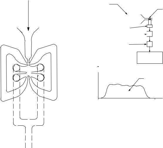
Fluidic Oscillator
Fluidics is a technology that was invented in 1959 and has been used in analogue and digital applications (32,33). It is very similar to pneumatics, but few or no moving parts are used. The devices can also be operated using liquids. The device that gave birth to the technology is the fluid amplifier, a device that with no moving parts can amplify a pressure differential. Figure 7 shows a cross-section of an amplifier, made by staking several perforated stainless steel sheets. Several amplifiers can be staged to achieve gains close to one-half of a million. The most successful fluidics device is the windshield water spray found in most cars. The windshield cleaning fluid or water enters into a cavity that makes the exiting jets oscillate, as shown in Fig. 8. Many applications are possible with this novel technology (34). It must be clarified that prior to the advent of MEMS and microchannels, the word ‘‘fluidics’’ was used
PNEUMOTACHOMETERS 371
Input/ |
Supply |
control |
port |
ports |
|
Supply nozzle
Vents
Splitter
Output ports
Figure 7. Fluidic fluid amplifier.
only in dealing specifically with this type of devices. Today, any small channel carrying a fluid is called a fluidic device or a microfluidic channel.
The fluidic oscillator flowmeter (unidirectional) offers much promise. It is constructed by configuring a fluid amplifier with feedback: the outputs are connected to the inputs, as shown in Fig. 9. This produces an oscillation whose frequency is proportional to flow. Even though this type of flowmeter has not been specifically used to measure respiratory flow, its performance has been demonstrated successfully as a flow sensor in gasoline delivery systems (35). It aspirates the displaced air in the fuel tank through small holes in the delivery nozzle. It withdraws a volumetric flow equal to the gasoline volumetric flow delivered to the tank. The purpose of course is to minimize the discharge of unburned hydrocarbons into the atmosphere.
Outlet
Initial |
Flow through |
condition |
feedback |
|
causes oscilation |
Figure 8. Fluidic windshield water spray.
372 |
PNEUMOTACHOMETERS |
|
|
|
|
|
Respiratory |
|
3L calibration syringe |
||
|
flow |
|
|
|
Fleish pneumotachometer |
|
|
|
|
|
|
|
|
|
|
|
|
|
|
|
|
|
|
|
|
|
|
|
|
|
|
|
|
|
|
|
|
|
|
|
|
Figure 9. Amplifier with positive feedback: fluidic oscillator.
COMMERCIALLY AVAILABLE SPIROMETERS
For a list of most of the commercially available spirometers, see the online source of information by ADVANCE for Managers of Respiratory Care (36) and American Association of Respiratory Care (37).
CALIBRATION
Calibration of Volume Displacement Type Spirometers
This type of volumetric device (Figs. 1 and 2) rarely loses calibration since the geometry is fixed, especially in the type where the measurements of the volume changes are recorded by means of a pen writing on a revolving graph. Even in systems that have electronic position sensors, due to the robustness of these components, recalibration is seldom necessary. However, recalibration should be done on a regular basis to insure the absence of artifacts such as leaks, rough spots, and so on.
The most common method for performing this procedure is the calibrated syringe: a large piston cylinder device that
Differential pressure transducer
Noise filtering (low pass) 

Signal amplification
Analog to digital converter and control unit
Vm
Area under the curve is 3 L
T Time
Figure 10. Syringe calibration procedure.
allows the piston to move within two stops and delivering a fixed volume (typically 3L). The calibration process consists of pulling the piston out to the outer stop, connecting the syringe to the spirometer, and gently pushing the piston to the other stop. The resulting volume indication should be that of the calibrated syringe volume.
Calibration of Spirometers other than the Volume Displacement Type
There are three approaches for calibrating pneumotachometer that do not utilize volume displacement. They are
(1) syringe, (2) wet test gas meter; and (3) comparison with a standard calibration flowmeter.
Syringe Approach. In performing this calibration procedure, it is assumed that the pneumotachometer is integrated into a data acquisition–calibration system. To perform the calibration, a fixed volume is passed through the pneumotachometer using a calibrated syringe, typically 3L. The data acquisition system records the resulting
flow signal, _ , as shown schematically in Fig. 10. Then it
V M
integrates it (i.e., finds the area under the curve) to obtain the measured volume:
VM ¼ Z TV˙ |
M dt |
0 |
|
Then it determines the correction factor, K, so that:
KVM ¼ 3
Afterward it uses K to adjust the measured flow:
˙ ˙
VTRUE ¼ KVM
PNEUMOTACHOMETERS 373
This approach assumes that the relationship between pressure drop and flow are linear. The user should consult the user’s manual, since some of the pneumotachometers automatically adjust for BTPS.
Wet Test Gas Meter. This device is similar to the gas meter found in homes and industrial sites (38). It consists of a series of constant volume chambers that are filled by the incoming flow. They are attached to a rotating structure that enables the chambers to go through the following sequence: (1) fill the chamber with the incoming air, (2) create a water seal at the bottom of the chamber, (3) move the sealed chamber to the exhaust side, and (4) release the volume in the chamber to the outside. As a result, the incoming flow imparts a rotation that is observable from the outside by means of rotating hands. Consequently, there is a 1:1 correlation between the volume that passes
through the device and the number of rotations indicated by the hand. To perform a calibration test, a known flow of gas is passed through the Wet Test Gas Meter and the flow recorded:
˙ ðnumber of revolutionsÞðvolume=revolutionÞ
V ¼
time required for above revolutions
Immediately afterward, the same flow is passed through the pneumotachometer under calibration. The constant flow is produced by applying a source of high pressure to a needle valve. Since the pressure resistance created by the Wet Test Gas Meter or the pneumotachometer is very small (a couple of inches of water), the flow is determined by the upstream pressure, Ps and the size of the orifice in the needle valve. The resulting output signal, e, is recorded, as shown in Fig. 11. The procedure is repeated for various needle valve settings to produce a curve similar to the one
Wet test gas meter
Flow source (created
by putting a high pressure source and a needle valve) is applied first
to the Wet Test Gas
Meter and then to pneumotach under test
|
Needle |
|
|
|
valve |
|
|
|
PS |
Fleish |
|
|
|
pneumotachometer |
|
Pressure |
VM |
Differential |
|
regulator |
|
||
|
pressure |
||
set to |
|
||
Pressure |
transducer |
||
50 psi |
|||
|
|||
(345 kPa) |
gauge |
|
|
|
|
Noise filtering |
|
|
|
(low pass filter) |
|
e |
|
|
|
|
|
Signal |
|
|
e |
amplification |
|
|
circuit |
||
|
Analog to digital |
|
|
|
converter and |
|
|
|
control unit |
|
VM
Figure 11. Calibration procedure using the Wet Test Gas Meter.

374 PNEUMOTACHOMETERS
Pressure regulator set to 50 psi
(345 kPa)
Figure 12. Calibration using a Laboratory grade Flowmeter.
Flow source (created
by putting a high pressure source and a needle valve) is applied first
to the laboratory-grade flowmeter and then to the pneumotach under test
Needle valve
VM
Pressure
gauge
Laboratory grade, calibration flowmeter
Fleish pneumotachometer under test
Differential pressure transducer
Noise filtering (low pass filter)
Signal amplification circuit
Analog to digital converter and control unit
shown in Fig. 11 that can then be used to obtain either a linear approximation or a polynomial fit. Afterward, the calculated flow is adjusted for conversion into standard conditions: BTPS [normal body temperature (36 8C) ambient pressure saturated with water vapor]. This type of calibration device has an accuracy of 0.5%.
Calibration Using a Laboratory Grade Flowmeter. This method is possible when a laboratory-grade flowmeter is available. As done in the Wet Test Gas Meter, a series of flows are passed through both the laboratory grade flowmeter and the pneumotachometer under test, as shown in Fig. 12. The output of the pneumotachometer under test is made to agree with the flow indicated by the laboratory grade flowmeter.
Piston Prover. Flow meters can also be calibrated using a piston prover (39). This device consists of a precision bore glass tube with a piston, that moves due to the displacement of the gas whose flow rate is being measured. The piston, which is slightly smaller than the bore of the tube, has a groove filled with mercury to create a leak-less, low friction seal. The flow is determined by the time that it takes for the piston to travel between two reference positions, timed using light beams. This device has an accuracy
of better than 0.2%. NIST provides calibration services for flowmeters using this technique and apparatus.
Soap Bubble Technique. From time to time, researchers need to measure a particular flow, but do not have the specialized calibration equipment required. In cases like this, the soap bubble technique can be used. It is implemented by placing a soap film across the open end of a constant, cross-section tube. The other end of the tube is connected to a barb fitting that will easily receive a plastic tubing through which the flow to be measured is passing. Next, the soap film is moved toward the other end (the side with the fitting), by using a source of vacuum that is momentarily connected to the end with the fitting. Then, the tubing with the flow to be measured is connected to fitting, and the time that it takes for the soap film to travel between two reference positions is recorded. This information is then used to calculate flow. This technique resembles the piston prover, except that a soap film is used instead of a piston.
PNEUMOTACHOMETER DYNAMIC CHARACTERISTICS
Another important characteristic of a pneumotachometer is its ability to measure rapidly changing flows. If one
PNEUMOTACHOMETERS 375
Signal |
|
|
|
|
|
|
|
generator |
Input |
|
Output |
Analyzer |
|
||
|
|
|
|
||||
|
|
|
|
|
|
||
|
|
signal |
|
signal |
|
|
|
|
|
|
System under test |
|
|
|
|
|
|
|
|
|
|
|
|
|
|
|
|
|
|
|
|
|
|
|
|
|
|
|
|
(a) General schematic
test |
fi |
|
Bi |
no |
|
||
1 |
|
|
|
2 |
|
|
|
3 |
|
|
|
... |
|
|
|
n |
|
|
|
(dB) |
20 |
|||
|
|
|
||
Magnitude |
0 |
|||
|
|
|||
|
|
|||
|
|
|||
|
|
|||
|
|
|
0 |
|
Phase (deg) |
|
|
|
|
|
|
|||
|
|
|||
|
|
|
||
|
|
|
|
|
101
Bi / A |
20 log( Bi / A ) |
Oi |
|
|
|
(b) Experimental data
Bode diagram
102 |
103 |
104 |
(c) Magnitude and phase Bode plot
Figure 13. Block diagram of procedure used for obtaining a frequency response test.
attempts to measure a fast changing flow signal with a flowmeter that does not have the adequate dynamic characteristics or ‘‘frequency response’’, one would obtain inaccurate results. One of the most common vehicles for capturing a device’s frequency response is called the Bode Plot (40). This section addresses the general test procedure and presentation format used for obtaining a frequency response or Bode plot. Afterward, it presents the method used for performing a frequency response test on flowmeters.
One of the fundamental properties of a linear system is that if the system is excited with a sinusoidal input signal, after the transients die out, its output will also exhibit a sinusoidal behavior. A frequency response test consists of applying sinusoids of different frequencies and measuring the amplitude of the output and the phase difference between the input and output. Figure 13a shows a sinu-
soidal generator producing a sine wave with amplitude A and frequency fi, being applied to a linear system. It also shows the corresponding output, another sinusoid of the same frequency, but with amplitude Bi and phase Fi. This procedure is repeated for different frequencies in order to obtain a table as shown Fig. 13b. Notice that the ratio of the output–input amplitude is calculated as well as 20 log of this ratio. This latter quantity has units called dB or deciBels in honor of the communication pioneer, Alexander Graham Bell. The Bode plot, which is actually made up of two plots, presents this information in graphical form. The magnitude plot shows the amplitude ratio in dB (i.e., 20 log Bi/A) on the vertical axis and the frequency [v ¼ 2pf ], in a logarithmic scale, on the horizontal axis. This is shown in Fig. 13c. Similarly, the Phase Bode Plot shows the phase against the various input frequencies. This is shown in Fig. 13d. The particular plot shown here is descriptive of a
376 PNEUMOTACHOMETERS
|
|
Differential |
Frequency |
|
|
pressure |
|
|
|
generator |
|
|
|
transducer |
|
|
|
and audio |
|
|
|
|
|
|
|
|
amplifier |
|
|
|
Speaker |
Analog to digital |
eV |
|
|
converter and |
|
||
|
|
||
control unit |
|
Fleish |
|
|
|
|
pneumotachometer |
etank pressure |
Signal |
Noise filtering |
|
|
amplification |
(low pass) |
|
Rigid tank
Figure 14. Test setup used for measuring frequency response of a pneumotachometer.
Differential pressure transducer
(one port open to ambient, other one to center tap into tank)
device that has low pass characteristics. This means that it passes signals of low frequencies at a constant gain (flat or horizontal portion), but attenuates ones that are of high frequencies (sloped portion of the graph). For any particular pneumotachometer application, it is desirable to use one that is flat in the range of frequencies that will be present in flow waveform that is to be measured. As an example of this, the ATS Standardization of Spirometry (18) stipulates, ‘‘Measuring PEF requires an instrument that has a frequency response that is flat ( 5%) up to
12Hz’’.
The reader may question the emphasis on sinusoidal
inputs when in the real world, very few signals are sinusoidal. Representation in terms of sinusoids provides a general framework for dealing with any type of periodic signals, periodic function can be decomposed into a summation of sinusoids (Fourier Series).
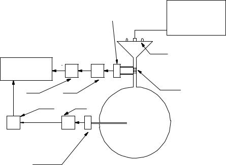
Performing a frequency response test on a pneumotachometer is more challenging than for an electronic device where both the input and output are electronic signals that are easily measurable. Development of this experimental procedure for pneumotachometers has been refined by Jackson and Vinegar (41). The test set up can be represented as shown in Fig. 14. For purposes of this explanation, assume that the pneumotachometer being tested is of the Fleish type, a fluid resistance with a pressure transducer for measurement of the pressure drop. To perform the frequency response test, a small loudspeaker is used to generate the sinusoidal flow that is applied to the pneumotachometer under test. On the other side of the pneumotachometer, a large, rigid tank is connected. Notice that because the tank is filled with ambient air, a compressible fluid, flow enters and exits it. Of course, when the flow enters the tank, the pressure in it increases, and when the flow exits, the pressure decreases. The experi-
mental procedure requires a second pressure transducer that measures the pressure inside the tank. This signal is used to calculate the flow in and out of the tank. Referring to Fig. 14,
eV_ measured is the pneumotachometer output signal (the output voltage of the pressure transducer connected to the
pneumotachometer) and etank pressure is the tank’s pressure transducer output signal. The flow into the tank is given by
˙ |
dðetank pressureÞ |
Vtrue ¼ K1 |
dt |
A frequency response test is performed by varying the frequency of the loudspeaker, collecting the data and plotting it in Bode format. The response is flat as long as the ratio of
eV_ measured=V_ true is constant.
CORRECTION FOR STANDARD CONDITIONS
Often the state in which the flow is measured is not reflective of the physiological conditions in which flow becomes meaningful. In other cases the calibration of the flowmeter takes place under a different set of conditions than what the flowmeter will experience in the clinical setting. In both cases, one needs to correct the resulting measurements to accurately capture the true physiological event happening. To illustrate the correction process, an example is provided here. Consider a pneumotachometer that is to be used for measurement of inspiratory flow. Further assume that the pneumotachometer has been calibrated with room air, using the standard 3L syringe. Consequently, there is no need to correct the flowmeter reading since it will measure properly the flow that passes through it during the test. That is, the conditions for calibration and clinical testing are the same. However,
PNEUMOTACHOMETERS 377
However, as the air travels through the airways, it is humidified. We assume that the total pressure remains constant as the air moves through the airways. Now the total pressure becomes:
Original |
|
unit volume |
|
entering |
|
mouth |
|
After |
|
temperature |
|
expansion |
Heat |
After |
Humidity |
humidity |
|
expansion |
|
Figure 15. Correction for volume expansion due to increase in temperature and humidity.
when the air enters the respiratory system, it experiences two changes: its temperature increases from room temperature to body temperature, and the humidity from 0% (assuming a very dry day) to 100% RH. Both of these processes need to be taken into consideration if it is desired to know the actual volume that is expanding the alveoli. In reality, both processes are happening simultaneously, but for purposes of this example, we will assume that the air is heated first and then it becomes saturated. Both of these transformations cause the air volume to expand. Figure 15 shows the expansion process.
The increase in temperature causes the air to expand (Dalton’s law of gasses). The correction factor for temperature is
Tbody þ 273:16 C
CFTemperature ¼ Tinlet þ 273:16 C
Assuming that the inlet temperature is 21.1 8C (70 8F) and that the body temperature 37 8C (98.6 8F) this correction
factor CFTemperature is 1.05.
The increase in humidity also creates an expansion. It is due to the effect of water vapor on the partial pressures. The total pressure of the dry gas is equal to the sum of the partial of its three main constituents N2, O2, and CO2.
Ptotal ¼ PN2 þ PO2 þ PCO2
Table 1. Normal Gas Concentrations of Aira
Ptotal ¼ PH2O þ PN2 þ PO2 þ PCO2
The presence of the partial pressure of the water vapor (PH2O) causes the sum of partial pressures of the last three constituents to decrease. This in turn causes the volume to expand. Thus the correction factor expression for humidity is
CFHUMIDITY ¼ pambient
pambient psat
Assume that the ambient barometric pressure is 29.92 mmHg (98.3 kPa) and at a body temperature of 36 8C, the water vapor pressure is 1.78 mmHg (6 kPa). Substituting these values into the previous equation pro-
duces a correction factor CFHUMIDITY of 1.06.
Combining both factors, the total correction factor becomes 1.12. This means that every milliliter that enters the mouth expands by 12% by the time that it reaches the alveoli. Consequently, measured flows need to be increased by 12%.
Comments about Complexities in the Measurement and Correction Process
More accurate (than the upper limits established by the ATS), bidirectional flow measurement is a challenging task when using pneumothachometers other than the volumetric type. This is true since the air volume varies due to density changes (resulting from temperature and composition differences of the incoming and outgoing air). The composition of inspired and expired air is shown in Table 1. The problem is made even more complicated if Fleish-type pneumotachometers are used, since now viscosity (the critical variable in the flow–pressure drop relationship) is influenced by both temperature and gas composition.
OVERVIEW OF DESIGN SPECIFICATIONS
This section presents some of the technical specifications of Fleish-type pneumotachometers, specifically those manufactured by Hans Rudolph a major manufacturer of respiratory components (42). These characteristics are shown in Table 2.
It is difficult to describe accuracy of each device in detail, since it depends not only on the hardware (i.e., resistive fluid sensor element) and the measurement process, but also on the correction factors that are applied (gas composition,
Source of sample |
Nitrogen (N2),% |
Oxygen (O2),% |
Carbon Dioxide (CO2),% |
Water Vapor (H2O),% |
Inspired air (dry) |
78.65 |
20.9 |
0.04 |
0.5 |
Alveolar air (saturated) |
75.45 |
13.2 |
5.2 |
6.2 |
Expired air (saturated) |
74.8 |
15.3 |
3.7 |
6.2 |
aAdapted from Ref. (42).

378 |
PNEUMOTACHOMETERS |
|
|
|
Table 2. Characteristics of Commercially Available Pneumotachsa,b |
|
|||
|
|
Flow Range |
Fluid Resistance |
Max. Pressure Drop at End of |
Application |
(L min 1) |
(mmH2O/(L min 1) |
Range (mmH2O) |
|
Premature (38 week gestational) |
0–10 |
1.0 |
10 |
|
Neonate (Birth to 1 month) |
0–10 |
0.70 |
7 |
|
Infant (1–12 month) |
0–35 |
0.20 |
7 |
|
Pediatrics |
|
0–100 |
0.10 |
10 |
Pediatrics |
|
0–160 |
0.10 |
16 |
Adults |
|
0–400 |
0.04 |
16 |
Adults |
|
0–800 |
0.02 |
16 |
aadapted from Ref. 43.
bNote: 1 psi ¼ 1 lbf/in2 ¼ 6.89 kPa ¼ 704 mmH2O.
temperature, relative humidity, differences between atmospheric conditions at the time of calibration and those at the time of use, and corrections for quadratic-type pressure drop). As mentioned before, most manufacturers simple indicate that their products meet the ATSs standards.
INDIRECT TECHNIQUES FOR MEASURING FLOW
There are various methods that provide an estimate of respiratory flow, by means of an indirect measurement. These techniques find an application in cases where continuous connection to a pneumotach through a mouthpiece or mark is not feasible.
INDUCTIVE PLETHYSMOGRAPHY
Respiratory inductive plethysmography (RIP) has been used for many years for respiratory monitoring. Used in intensive care units worldwide for monitoring respiratory activity, primarily tidal volume. During inspiration, due to the bucket-handle effect of the ribs and the outward displacement of the abdomen, there is an increase in the crosssectional area of the rib cage and abdomen, which translates into an increase in circumference (or more accurately, perimeter). This increase in perimeter is measured using elastic bands and correlated to a specific lung volume increase, or often used as a simple, relative measurement of lung volume expansion.
This technique used by the LifeShirt (44) is a vest-like, portable physiological monitoring system. In the LifeShirt, ‘‘two parallel, sinusoidal arrays of insulated wires embedded in elastic bands are woven into a flexible garmet. Extremely low voltage electrical current is passed through the wire creating an oscillating circuit. As the body chambers expand and contract, the electrical sensors generate different magnetic fields that are converted into proportional voltage changes over time (i.e., waveforms)’’. For calibration, which is done immediately after putting on the vest, the user breathes into a fixed-volume, calibration bag. Then the associated tidal volume is correlated to the measured body’s expansion.
Respiratory Sounds
There is a correlation between respiratory flow and breath sounds. This method has been pursued for many years and
continues to be an ongoing topic for research (45,46). Tracheal breath sounds are preferred by many investigators since they are louder than chest sounds and since there is more correlation of flow at the trachea and less filtering from the chest wall (47).
The U.S. Army (48) has been extremely active in developing physiological monitoring systems based on the sounds detected at the neck. Their motivation for this research is based on the premise that continuous monitoring of the soldier’s health ‘‘can provide exceptional improvement to survivability, mobility, and lethality’’ (49). This group has generated a considerable amount of methodology as well as easy-to-build sensors and equipment for this application (50,51).
Some development has been done to obtain an estimate of actual flow from respiratory sounds (instantaneous measurement of the magnitude and direction of respiratory flow) (52). This is possible since inspiration and expiration have different ‘‘sounds’’, due to the asymmetrical nature of the respiratory passageways. This approach is implemented by initially, simultaneous measuring both tracheal sounds (using a small microphone attached to the neck) and actual flow (using a standard pneumotachometer). After recording data for 1–2 min, these two waveforms that are fed into a computer program that produces a correlation algorithm, which can be used subsequently to predict flow (magnitude and direction) from the tracheal sounds. The long-terms aim of this effort is detection of SIDS candidacy. The basic concept is that there might be a flow patterns/signature that could be construe as an early-predictor of SIDS. This test would be done during the first night that a newborn spends at the hospital. If a suspicious pattern is found, then a baby monitor could be sent home with the baby. It could also find application in the analysis the breathing patterns of athletes (in which a mouthpiece-tachometer is not feasible).
SUMMARY
Pneumotachometers have contributed and will continue to contribute significantly to our understanding of the respiratory system. They are an essential tool in the fight against respiratory diseases. In addition new applications are being developed that aim at the prevention of disease.
BIBLIOGRAPHY
1.The Bible, Chapter 2, verse 7.
2.Rupple G. Manual of Pulmonary Function Testing. 2nd ed. St. Louis: C.V. Mosby Company; 1979.
3.Fishman AP. Assessment of Pulmonary Function. New York: McGraw-Hill; 1980.
4.Nunn JF. Applied respiratory Physiology. 4th ed.
5.Pimmel R, Fullon JM. Characterizing Respiratory Mechanics with Excitation Techniques. Ann Biomed Eng 1982;9:475–488.
6.Bakos JH. Estimation of the Total Respiratory Parameters in Paralyzed and Free-breathing Rabbits by the Technique of Forced Oscillation, M.S. dissentation, Pennsylvania State University; 1979.
7.Tsai MJ, et al. Respiratory parameter estimation using forced oscillatory impedance data. J Appl Physiol 1977; 43(2):322– 330.
8.Goldman MD. Clinical applications of forced oscillation. Pulmonary Pharmacol Therapeut 2001;14:341–350.
9.Schmid-Schoenbein GW, Fung YC. Forced perturbation of respiratory system: (A) The traditional model. Ann Biomed Eng 1978;6:194–211.
10.Schmid-Schoenbein GW, Fung YC. Forced perturbation of respiratory system: (B) A continuum mechanics analysis. Ann Biomed Eng 1978;6:367–398.
11.Macia NF, Dorson WJ, Higgins WT Jr. Lung-diaphragm Model of the Respiratory System for Parameter Estimation Studies Presented at the 1997 International Mechanical Engineering Congress & Exposition, Dallas, TX, November 1997.
12.Macia NF. Noninvasive, Quick Obstruction Estimation Method for the Measurement of Parameters in the Nonlinear Lung Model, Ph.D. dissertation, Arizona State University, August 1988.
13.McPherson SP. Respiratory Therapy Equipment. 2nd ed. St. Louis: C.V. Mosby Co.; 1981.
14.Cherniack RM, Brown E. A simple method for measuring respiratory compliance: Normal values for males. J Appl Physiol 1965;20(1):
15.Merth IT, Quanjer PH. Respiratory system compliance assessed by the multiple occlusion and weighted spirometer method in non-intubated healthy newborns. Pediatr-Pulmonol 1990;8(4):273–279.
16.Crawford S. Automated System for Measurement of Total Respiratory Compliance, Applied Project Report, Arizona State University East, 2003 (paper also under preparation).
17.Fleish A. Der Pneumotachograph-ein Apparat zur Geshwindigkertsregistrierung der Atemluft Pflugers. Arch Gas Physiol 1925;209:713.
18.The American Thoracic Society, Standardization of Spirometry, 1994 Update. Standardization of Spirometry, 1994 Update. Am J Respir Crit Care Med 1995;152:1107–1136.
19.Osborne JJ. Monitoring respiratory function. Crit Care Med 1974;2:217.
20.Osborne JJ. A flowmeter for respiratory monitoring. Crit Care Med 1978;6:349.
21.Sukes MK, NcNicol MW, Campbell EJM. Respiratory Failure. 2nd ed. Oxford (UK): Blackwell Scientific Publications; 1976.
22.Wright Respiratoy, Harris Calorific; Cleveland, Ohio.
23.ndd Medical technologies, 17 Progress Ave., Chelmsford, (MA), www.nddmed.com.
24.Sulton FD, Nett LM,Petty TL. A new ventilation monitor for the intensive care unit. Care Resp 1974;19:196.
25.Petty TL. Intensive and Rehabilitative Respiratory Care. 2nd ed. Lea and Febiger: Philadelphia; 1974.
PNEUMOTACHOMETERS 379
26.McShane JL, Geil FG. Measuring flow. Res/Devel February 1975; 30.
27.Frederick G. Application of bluff body vortex shedding and fluidic circuit techniques to control of volumetric flow, M.S.E. dissentation; Arizona State University; 1974.
28.Bourns Medical Systems, Riverside (CA).
29.Svedin N, Ka¨lvesten E, Stemme G. A new edge-detected lift force flow sensor presented at The 10th International Conference on Solid-State Sensors and Actuators (TRANSDUCERS’99) in Sendai, Japan; June 7–10, 1999.
30.Svedin N. A lift force flow sensor designed for acceleration insensitivity. Sensors Actuators 1998;68(1–3): 263–268.
31.Svedin N. A new silicon gas-flow sensor based on lift force. IEEE/ASME J Microelectromech Syst 1998;7(3):303–308.
32.Behrens CW. What is fluidics. Appl Manuf July 1968.
33.Fluidics flown on. The Engineer 28 June 1990.
34.Drzewiecki TM, Macia NF. Fluidic Technology: Adding Control, Computation and Sensing Capability to Microfluidics., Smart Sensors, Actuators, and MEMS conference at SPIE’s International Symposium on Microtechnologies for the New Millennium, Gran Canaria, Spain; May 2003.
35.Thurston J. Personal communications, Honeywell, Tempe, (AZ).
36.ADVANCE for Managers of Respiratory Care, www. ADVANCEforMRC.com.
37.American Association of Respiratory Care, www.aarc.org and http://buyersguide.aarc.org/.
38.Varlen Instruments Inc., 2777 Washington Blvd, Bellwood, IL 60104, (800) 648-3954.
39.Wright JD, Matingsly GE. NIST Calibration Services for Gas Flow Meters. NIST special Publication 250–49.
40.Macia NF, Thaler GJ. Modeling and Control of Dynamic Systems. Thomson Delmar Learning; 2004.
41.Jackson AC, Vinegar A. A technique for measuring frequency responses of pressure, volume and flow transducers. J Appl Physio Respirat Environ Excercise Physiol 1979;47(2): 462–467.
42.Martini FH. Fundamentals of Anatomy and Physiology. 4th ed. New York: Prentice Hall; 1998.
43.Hans Rudolph, Inc., Kansas City, Mo., www.rudolphkc.com.
44.Vivo Metrics, Inc. Venturo, CA, www.vivometrics.com.
45.Graviely N. Breath Sounds Methodology. Boca Raton (FL): CRC Press; 1995.
46.Soufflet G, et al. Interaction between tracheal sound and flow rate: A comparison of some flow evaluations for lung sounds. IEEE Trans Biomed Eng 1990;37(4):
47.Mussell MJ, Nakazono Y, Miyamoto Y. Effect of air flow and flow transducer on tracheal breath sounds. Med Biol Eng Comput November 1990.
48.www.arl.army.mil/sed/acoustics.
49.Scanlon MV. Acoustic Sensor Array Element Extracts Physiology During Movement (internal document, available at the above, Army web site)
50.Scanlon MV. Acoustics Sensor for Health Status Monitoring. Proceeding of IRIS Acoustic and Seismic Sensing. 1998. Vol. II, 205–222. (Also available at the above, Army web site.)
51.Bass JD, Scanlon MV, Mills TK, Morgan JJ. Getting Two Birds with one Phone: An acoustic sensor for both speech recognition and medical monitoring. presented in poster format at the 138th Meeting of the Acoustical Society of America. November, 1999. (Also available at the above, Army web site.)
52.Gudala SG. Estimation of Air Flow from Tracheal Breath Sounds, Master of Technology Applied Project, Arizona State University East; May 2003.
See also PULMONARY PHYSIOLOGY; RESPIRATORY MECHANICS AND GAS EXCHANGE; VENTILATORY MONITORING.