

Molecular and Cellular Signaling - Martin Beckerman
.pdf482 19. Ion Channels
increasing resolution by electron microscopy for 30 years. Receptor ion channel subunits consist of several segments connected by flexible disordered loops. As a result of this architecture it is difficult to impossible to make crystals from entire subunit chains. However, crystals can be fabricated from portions of the subunits. Receptor ion channels, like so many other proteins, are highly modular, and this modularity can be exploited to arrive at a consistent picture of how the ion channels work by studying the channels part-by-part.
Each acetylcholine receptor subunit possesses an N-terminal ligandbinding domain, a transmembrane segment, and an intracellular region. As depicted in Figure 19.5(c), the extracellular, ligand-binding domain is quite large. There are four transmembrane segments and there is a substantial cytoplasmic region. The ligand binding domain is capable of binding not only to agonists, but also to antagonists. When an agonist binds the ligand binding domain the channel formed by the transmembrane segments rapidly opens to permit the passive diffusion of cations leading to a depolarization of the muscle cell’s postsynaptic membrane and contraction of the muscle.
The acetylcholine-binding protein (AChBP) from the snail L. stagnalis is almost identical in size and in residues crucial for ligand binding to the N- terminal ligand binding domains of nAchRs. It lacks the transmembrane and cytoplasmic segments present in mammalian AChRs. It can be crystallized and serves as an archetypal example of a ligand binding domain. Shown in Figure 19.10 are two views of the pentamer formed by five iden-
FIGURE 19.10. Structure of the ligand-binding domain of the acetylcholine-binding protein: (a) Top view showing the ringlike arrangement of the five subunits to form a conducting pore. Each subunit is shown in a different shade of gray. (b) Side view of the ring highlighting the two units located in the foreground. The N-terminus is at the top and the C-terminus is at the bottom of each subunit. The figure was generated using Protein Explorer with atomic coordinates deposited in the Brookhaven Protein Data Bank under accession code 1I9B.

19.11 Operation of Glutamate Receptor Ion Channels |
483 |
tical AChBPs. The pore formed by the five subunits is clearly visible in this figure. As might be expected the residues lining the inner wall of the pore are highly hydrophilic, and many are charged. A ligand-binding site is present in a cavity formed at the interface between each adjacent subunit. The cavity, positioned towards the outside of the ring, is formed by a set of loops from one subunit and a series of beta strands from the other unit. Since there are five interfaces, the ligand binding domain can bind up to five ligands.
19.11 Operation of Glutamate Receptor
Ion Channels
The second family of ligand gated ion channels is the glutamate family. Glutamate receptor ion channels are prominent components of sensory processing systems and contribute greatly to learning and memory processes. They are found on the postsynaptic side of sensory/information-processing neurons. Referring back to the Hodgkin–Huxley model, the cys-loop and glutamate receptor ion channels give rise to synaptic currents in the postsynaptic cells. The flow of ions through these channels leads to changes in membrane voltage. By this means, the ligand-gated ion channels communicate and work together with the voltage-gated channels in these cells to control membrane excitability and convey signals. In addition to mediating changes in membrane voltage, calcium is itself a second messenger and thus functions as a key signaling intermediary.
The core chains of glutamate receptors pass through the plasma membrane three times. The N-terminal is positioned in the extracellular spaces and the C-terminal is situated in the cytoplasm as illustrated in Figure 19.5(d). A pore-forming reentrant (M2) loop is situated between the first two transmembrane portions of the chain. Two extracellular sequences (S1 and S2) form the ligand-binding domain. One of these is located just after the amino terminus; the other occurs between M3 and M4. The conducting channel is assembled from four subunits. The subunits may be identical or they may be mixtures of different subunit types. Because of their modular structure, one kind of subunit may be swapped for another in response to regulatory signals thereby altering the biophysical properties of the channel.
Several kinds of receptors bind the neurotransmitter glutamate. Some ionotropic glutamate receptors (iGluRs) bind AMPA with high affinity while others bind either kainite or NMDA. The subunits belonging to each of the three groups of iGluRs are listed in the table. Like the acetylcholine receptors, the glutamate receptors are highly modular. They contain an N- terminal extracellular domain followed by an extracellular ligand binding domain, three transmembrane segments plus a reentrant loop, and a C- terminal cytoplasmic region.
484 19. Ion Channels
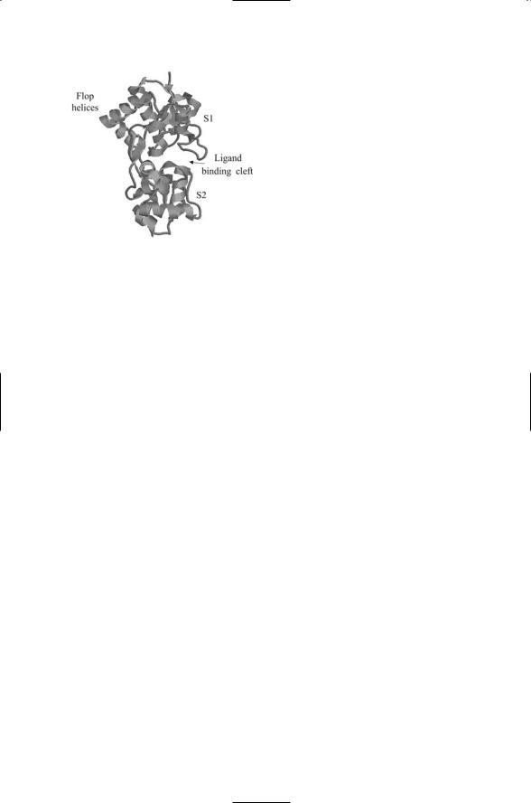
FIGURE 19.11. The S1S2 ligand-binding domain of the AMPA receptor: The S1, S2, and Flop regions of the polypeptide chain used in the S1S2 construct are identified in Figure 19.5(d). The figure was generated using Protein Explorer with atomic coordinates deposited in the Brookhaven Protein Data Bank under accession code 1FW0.
Glutamate receptor ion channels are responsible for most of the excitatory signaling in the brain. These receptors are most likely homoand heterotetrameric assemblages of subunits. They assemble in several stages. Individual subunits first associate to form dimers, and these dimers then associate to form dimers of dimers. Like the voltage-gated ion channels, the receptor ion channels have open and closed conformations. Ligand binding results in stabilization of the open configuration through an allosteric mechanism. The receptors do not remain open indefinitely, but rather desensitize and go back to a closed conformation soon (within milliseconds) after ligand binding.
The S1S2 ligand-binding domain of an AMPA receptor is depicted in Figure 19.11. The S1S2 domain depicted in this figure is a laboratory construct made by cutting the polypeptide chain and then joining together the S1 and S2 + Flop segments using a 13-residue-long linker. The result is a ligand-binding domain that replicates the actions of the natural extracellular unit without the encumbrances of the other loops and transmembrane segments. As can be seen in Figure 19.11 the S1 and S2 semidomains form a pair of jaws that grip the ligand. In the absence of ligand binding, the jaws are open, but they close upon binding the ligand. The amount of jaw closing is variable, and depends on which of several different kinds of ligands are being bound. Binding by antagonists stabilizes the S1S2 domain in an open configuration; the jaws partially close in response to binding by partial agonists such as kainite, and close more fully in the presence of glutamate.
The jaws are mechanically coupled of the gate. A linker that connects the jaws to the membrane-spanning helices provides the mechanical coupling. In the dimeric form, there are two linkers, one for each subunit. The linkers move apart from one another as the jaws close and move nearer one another when the jaws open. This movement opens and closes the gate. When the jaws are open the gate is closed and when the jaws close through agonist binding the gate opens.

References and Further Reading |
485 |
Ions flow into the cell when the gate opens. The gate does not remain open for very long, just a few milliseconds. The gate then closes even though the ligand remains bound. The closing of the gate is brought on by rearrangements of the dimer interface. The interface between subunits in the dimer is placed under strain by the gate opening. The rearrangements of the dimer interface relieve this strain by disengaging the conformation changes brought on by agonist binding and shutting the gate, resulting in receptor desensitization (to the ligand binding).
References and Further Reading
General References
Hille B [1992]. Ionic Channels of Excitable Membranes (2nd edition). Sunderland MA: Sinauer Associates, Inc.
Kaczmarek LK, and Levitan IB [1987]. Neuromodulation. New York: Oxford University Press, Inc.
Nicholls JG, Wallace BG, Fuchs PA, and Martin AR [2001]. From Neuron to Brain: A Cellular Approach to the Function of the Nervous System (4th edition).
Sunderland MA: Sinauer Associates, Inc.
Voltage-Gated Potassium Channel
Doyle DA, et al. [1998]. The structure of the potassium channel: Molecular basis of K+ conduction and selectivity. Science, 280: 69–77.
Jiang YX, et al. [2003]. X-ray structure of a voltage-dependent K+ channel. Nature, 423: 33–41.
Jiang YX, et al. [2003]. The principle of gating charge movement in a voltagedependent K+ channel. Nature, 423: 42–48.
Perozo E, Cortes DM, and Cuello LG [1999]. Structural rearrangements underlying K+-channel activation gating. Science, 285: 73–78.
Roux B, and MacKinnon R [1999]. The cavity and pore helices in the KcsA K+ channel: Electrostatic stabilization of monovalent cations. Science, 285: 100–102.
Schrempf H, et al. [1995]. A prokaryotic potassium ion channel with two predicted transmembrane segments from Streptomyces lividans. EMBO J., 14: 5170–5178.
Yellen G [2002]. The voltage-gated potassium channels and their relatives. Nature, 419: 35–42.
Voltage-Gated Sodium Channels
Caterall WA [2000]. From ionic currents to molecular mechanisms: The structure and function of voltage-gated sodium channels. Neuron, 26: 13–25.
Voltage-Gated Anion (Chloride) Channels
Dutzler R, Campbell EB, and MacKinnon R [2003]. Gating the selectivity filter in ClC chloride channels. Science, 300: 108–112.
Dutzler R, et al. [2002]. X-ray structure of a ClC chloride channel at 3.0 Å reveals the molecular basis of anion selectivity. Nature, 415: 287–294.

486 19. Ion Channels
Acetylcholine Receptor Ion Channels
Brejc K, et al. [2001]. Crystal structure of an Ach-binding protein reveals the ligand binding domain of nicotinic receptors. Nature, 411: 269–276.
Cordero-Erausquin M, et al. [2000]. Nicotinic receptor function: New perspectives from knockout mice. Trends Pharmacol. Sci., 21: 211–217.
Karlin A [2002]. Emerging structure of the nicotinic acetylcholine receptors. Nature Rev. Neurosci., 3: 102–114.
Miyazawa A, Fujiyoshi Y, and Unwin N [2003]. Structure and gating mechanism of the acetylcholine receptor pore. Nature, 423: 949–955.
Miyazawa A, et al. [1999]. Nicotinic acetylcholine receptor at 4.6 Å resolution: transverse tunnels in the channel wall. J. Mol. Biol. 288: 765–786.
Glutamate Receptor Ion Channels
Armstrong N, and Gouaux E [2000]. Mechanism for activation and antagonism of an AMPA-sensitive glutamate receptor: Crystal structure of the GluR2 ligand binding core. Neuron, 28: 165–181.
Ayalon G, and Stern-Bach Y [2001]. Functional assembly of AMPA and kainite receptors is mediated by several discrete protein-protein interactions. Neuron, 13: 103–113.
Madden DR [2002]. The structure and function of glutamate receptor ion channels.
Nature Rev. Neurosci., 3: 91–101.
Sun Y, et al. [2002]. Mechanism of glutamate receptor desensitization. Nature, 417: 245–2253.
Problems
19.1 Using the Nernst equation with R = 8.31 Joule/deg (K) mol and F = 9.65 ¥ 104 C/mol, calculate the equilibrium potential for potassium, sodium, and chloride ions at 20 degree Celsius for the inside and outside concentrations presented in Figure 19.1.
19.2 Calculate the reversal potential using the Goldman–Hodgkin–Katz equation for the concentrations presented in Table 19.1 with the following ratios of permeability constants: pNa/pK = 0.05 and pCl /pK = 0.2.
19.3 Sketch the time course of the sodium and potassium permeabilities using Figure 19.2 as the template. Sketch the behavior of the action potential produced by the sodium and potassium currents over that time period. Assume a maximum positive value of +20 mV and a maximum negative value of -70 mV, and indicate in the plot where the action potential will reach these maximum and minimum values.

20
Neural Rhythms
The focus in the last chapter was on the potassium and sodium ion channels responsible for generating action potentials in neurons. This subject is developed further in the present chapter where the emphasis shifts towards how ion channels generate rhythmic discharges in neurons. Voltage-gated ion channels, currents flowing through ligand-gated ion channels located in chemical synapses (synaptic currents), and electrical synapses (gap junc- tions)—all these contribute to the generation of neural rhythms. A variety of patterns can be produced, some in small populations of cells and others in large ones. Rhythmic patterns among large populations of neurons are associated with different sleep states and with states of arousal and attention. Small circuits of neurons known as central pattern generators generate rhythmic behavior in motor systems. These circuits control heartbeat, regulate respiration, and control locomotion, chewing, and digestion.
This subject of the nervous system concludes in the last chapter, where the focus will be on the chemical synapse—on how it is organized and how it promotes learning and memory formation. The organization of the sensory cortices will be looked at along with how they process sensory information that is relayed in from sensory organs. Special attention will be given to the glutamate receptor ion channels and their central role in sensory information processing, learning, and memory formation.
This chapter is divided into three parts. In the first part, pacemaker cells will be introduced in a discussion of heartbeat. In the middle part of the chapter, the low frequency synchronous firing of large populations of cells will be examined. The main focus will be on sleep oscillations and how these forms of rhythmicity may change into abnormal epileptic seizures. The third part of the chapter will deal with how central pattern generators drive muscle contractions, drawing on several invertebrate systems for examples.
20.1 Heartbeat Is Generated by Pacemaker Cells
Heartbeat is generated by rhythmic discharges from nerve cells situated in a small region of the heart called the sinoatrial node (SAN) located in the wall of the right atrium. Impulses from the SAN are distributed rapidly
487

488 20. Neural Rhythms
throughout the heart by a specialized conduction system and cause the rhythmic contractions of the heart muscle. Impulses from the SAN are sent to the atrioventricular node (AVN) and left and right bundles of Purkinje fibers, and then to locations throughout the heart. The cells in the SAN that generate the rhythmic impulses do not require rhythmic input, but instead generate the rhythmic patterns by themselves. Other neurons in the conduction system respond to the pacemaker cells by firing in synchrony with them. In the absence of input from the SAN, nerve cells in the AVN and the Purkinje fibers can act as pacemakers, but they fire at a lower frequency. These cells, along with other nonpacemaking cells, can be driven by the SAN neurons and made to fire in synchrony with them.
The ability to generate rhythmic discharges is due to the mix of ion channels expressed by the neurons in the SAN and other regions of the heart. Since the function of the neurons in each of the regions is slightly different, the neurons in these regions express slightly different mixes of ion channels. The main ion channels contributing to the action potentials in the heart are listed in Table 20.1. The ion channels each have a specific function, as listed in column 3. The meanings of the terms appearing in that column are illustrated in Figures 20.1 and 20.2.
The first entry in Table 20.1, the sodium channel, generates fast upstrokes that are pronounced in non-SAN neurons. Funny (f ) channels in the heart are responsible for diastolic depolarization in SAN neurons. These same ion channels are called Ih channels in the brain and are referred to as HCN channels in the next section. The term diastolic depolarization refers to the rising (depolarization) portion of the action potential occurring at the very end of the SAN action potential. This depolarization allows the SAN neurons to immediately fire another action potential after completion of a previous one, and thus enables the SAN neurons to function as the pacemakers for the entire heart. The firing appears as the rising part of the action potential for the SAN neuron that occurs after the late repolarization stage, as shown in Figure 20.2.
Neurons express several different kinds of calcium channels. Some calcium channels are called “L-type” while others are referred to as being “N-” or “P/Q-” or “R-” or “T-type.” Most of the calcium channels are acti-
TABLE 20.1. Ion |
currents contributing to the firing |
properties of neurons |
in the heart. |
|
|
Cardiac current |
Description |
Function |
|
|
|
INa |
TTX sensitive, inward Na+ current |
Fast upstroke |
If |
Hyperpolarization-activated inward |
Diastolic depolarization |
|
nonselective cation (Na+, K+) current |
|
ICa,L; iCa,T |
L- and T-type inward Ca2+ currents |
Plateau |
IKr,Ks |
Rapid (r) and slow (s) delayed rectifying |
Late repolarization |
|
outward K+ currents |
|
It0,sus |
4-AP sensitive, transient (t0) and sustained |
Early repolarization |
|
(sus) outward K+ currents |
|
20.2 HCN Channels’ Role in Pacemaker Activities |
489 |
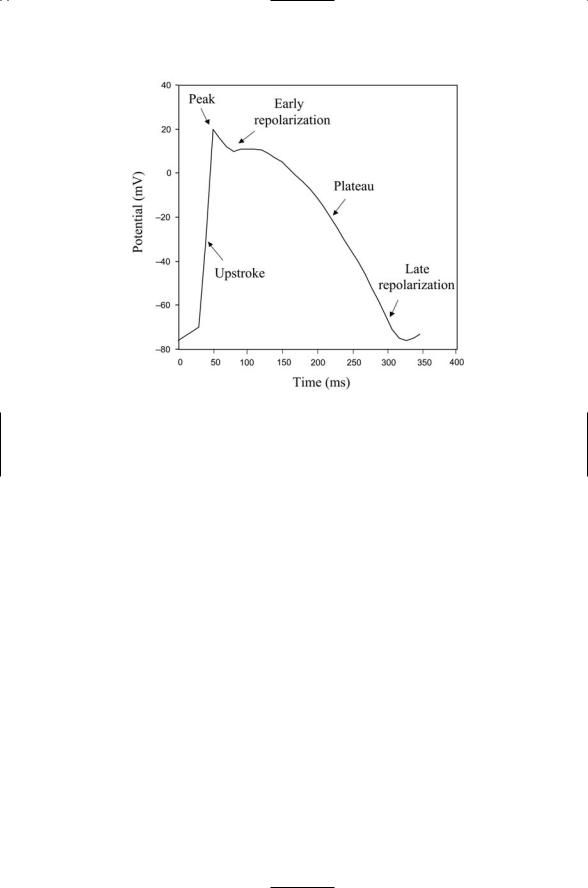
FIGURE 20.1. Stereotypic cardiac action potential: A stereotypic action potential of the form found in the heart is depicted. The rapid depolarization of the membrane, or upstroke, leads to a peak membrane potential of +10 to +20 mV. Once the peak depolarization is achieved there is an early phase of repolarization followed by a slow and sometimes flat regime called a “plateau,” and then a late, or final, repolarization phase a few hundred milliseconds after the start of the upstroke.
vated by large depolarization while a few, most notably the T-type channels, require only mild depolarization of the membrane. The calcium channels requiring large depolarization are referred to as high voltage-activated (HVA) calcium channels whereas the T-type channels are termed low voltage-activated (LVA). The calcium currents found in the heart help maintain action potential plateaus, the fairly flat and slowly declining portions of the action potentials. Lastly, the potassium currents related in the last two sets of entries in Table 20.1 are responsible for the early and late phases of action potential repolarization.
20.2 HCN Channels’ Role in Pacemaker Activities
Hyperopolarization-activated cyclic nucleotide-gated channels contribute to pacemaker activities in the sinoatrial node. The HCN (hyperpolarizationactivated cyclic nucleotide-gated) channel is regulated both by cyclic nucleotides such as cAMP and by voltage. It is a member of the 6 TM family of ion channels and possesses a cAMP-binding domain in its cytoplasmic

490 20. Neural Rhythms
FIGURE 20.2. Action potentials in different parts of the heart: Shown are action potentials in the sinoatrial node (SAN) and in the ventricles. The latter are delayed by the amount of time required for the pulse from the SAN to reach the ventricular fibers. The minimum, hyperpolarized values of the membrane potentials are listed just below the dashed lines.
TABLE 20.2. Collective firing patterns observed in electroencephalograph recordings in the brain.
Type of activity |
Frequency |
Association |
Delta waves |
0.5 to 4 Hz |
Deep sleep, abnormal states |
Theta waves |
4 to 8 Hz |
Sleep onset, abnormal states |
Alpha waves |
8 to 12 Hz |
Drowsiness and relaxed activity |
Spindling oscillations |
7 to 14 Hz |
Quiescent sleep |
Beta waves |
12 to 30 Hz |
Arousal, alert states, and information processing |
Gamma band |
30 to 60 Hz |
Arousal, alert states, and information processing |
|
|
|
C-terminal region. Its voltage regulation is unusual. Most ion channels are activated by depolarization. As discussed in the last chapter, their activation gates are closed at resting membrane potentials but open when the membrane is depolarized beyond some threshold level. The HCN channels work the opposite way. They are activated when the membrane potential is hyperpolarized beyond values in the range -50 to -70 mV. Whenever a cell fires an action potential the membrane hyperpolarizes and the HCN
20.2 HCN Channels’ Role in Pacemaker Activities |
491 |
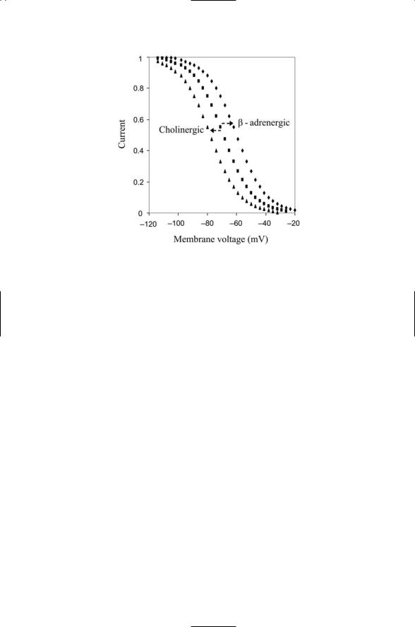
FIGURE 20.3. Activation functions for the hyperpolarization-activated cation current: The HCN channels are activated by hyperpolarization. b-adrenergic (adrenaline) stimulation shifts the activation function towards more depolarized values, while cholinergic (acetylcholine) stimulation does the opposite, shifting the activation function to more hyperpolarized values.
channel opens. Whereas the potassium channels responsible for the descending phase of the action potential has a reversal potential that is more negative than the resting membrane potential, the HCN channels exhibits the opposite voltage relationship. Its reversal potential is in the range from -20 to -30 mV, values that are less negative than that of the resting potential. When the HCN channel opens both Na+ and K+ ions flow into the cell to depolarize the membrane. The presence of HCN channels provides a means of moving the membrane potential in the direction needed to trigger action potentials and thus renders the cell more excitable.
The biophysical properties of ion channels can be altered by neuromodulators acting in a variety of ways. Two examples of neurmodulation are included in Figure 20.3. Cardiac sinoatrial node neurons express b- adrenergic and cholinergic G protein-coupled receptors (GPCR). When adrenaline binds to a GPCR, Gs alpha subunits are activated. As discussed in Chapter 12, these subunits stimulate adenylyl cyclase to increase its the production of cAMP. The cAMP molecules diffuse to and bind the cytoplasmic portion of the HCN ion channels. This binding shifts the activation curve towards less negative membrane potentials. As a result the neurons are able to fire action potentials more rapidly and the heart rate goes up. Acetylcholine has the opposite effect. When it binds its GPCR, Gi alpha subunits are activated. These molecules bind to adenylyl cyclase and throt-