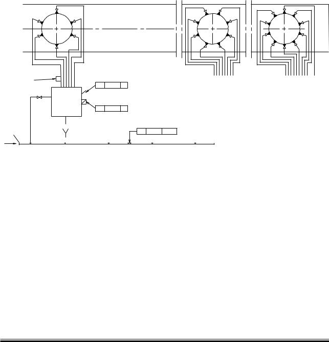
The MAN B&W Alpha cylinder lubrication system, see Figs. 9.02.02a and 9.02.02b, is designed to supply cylinder oil intermittently, e.g. every four engine revolutions with electronically controlled timing and dosage at a defined position.
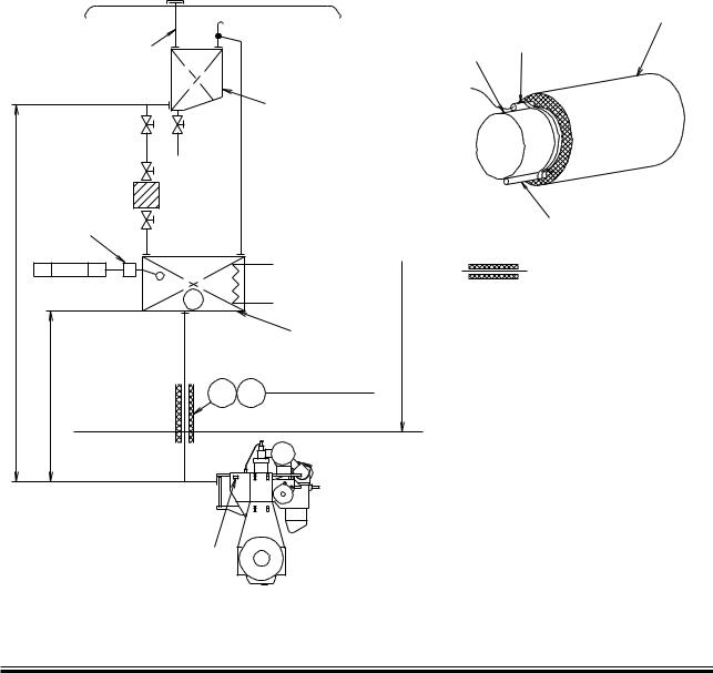
The cylinder lubricating oil is pumped from the cylinder oil storage tank to the service tank, the size of which depends on the owner’s and the yard’s requirements, it is normally dimensioned for minimum two days’ cylinder lubricating oil consumption.
Cylinder lubricating oil is fed to the Alpha cylinder lubrication system by gravity from the service tank.
The storage tank and the service tank may alternatively be one and the same tank.
The oil fed to the injectors is pressurised by means of the Alpha Lubricator which is placed on the HCU and equipped with small multi piston pumps.
The oil pipes fitted on the engine is shown in Fig. 9.02.04.
The whole system is controlled by the Cylinder Control Unit (CCU) which controls the injection frequency on the basis of the engine speed signal given by the tacho signal and the fuel index.
Prior to start-up, the cylinders can be pre lubric ated and, during the running in period, the operator can choose to increase the lubricating oil feed rate to a max. setting of 200%.
The MAN B&W Alpha Cylinder Lubricator is preferably to be controlled in accordance with the Alpha ACC (Adaptive Cylinder oil Control) feed rate system.
The yard supply should be according to the items shown in Fig. 9.02.02a within the broken line. With regard to the filter and the small box, plese see Fig. 9.02.05.
Alpha Adaptive Cylinder oil
Control (Alpha ACC)
It is a well known fact that the actual need for cylinder oil quantity varies with the operational conditions such as load and fuel oil quality. Consequently, in order to perform the optimal lubrication – cost effectively as well as technically – the cylinder lubricating oil dosage should follow such operational variations accordingly.
The Alpha lubricating system offers the possibility of saving a considerable amount of cylinder lubricating oil per year and, at the same time, to obtain a safer and more predictable cylinder condition.
Working Principle
The basic feed rate control should be adjusted in relation to the actual fuel quality and amount being burnt at any given time. The sulphur percentage is a good indicator in relation to wear, and an oil dosage proportional to the sulphur level will give the best overall cylinder condition.
The following two criteria determine the control:
•The cylinder oil dosage shall be proportional to the sulphur percentage in the fuel
•The cylinder oil dosage shall be proportional to the engine load (i.e. the amount of fuel entering the cylinders).
The implementation of the above two criteria will lead to an optimal cylinder oil dosage, proportional to the amount of sulphur entering the cylinders.
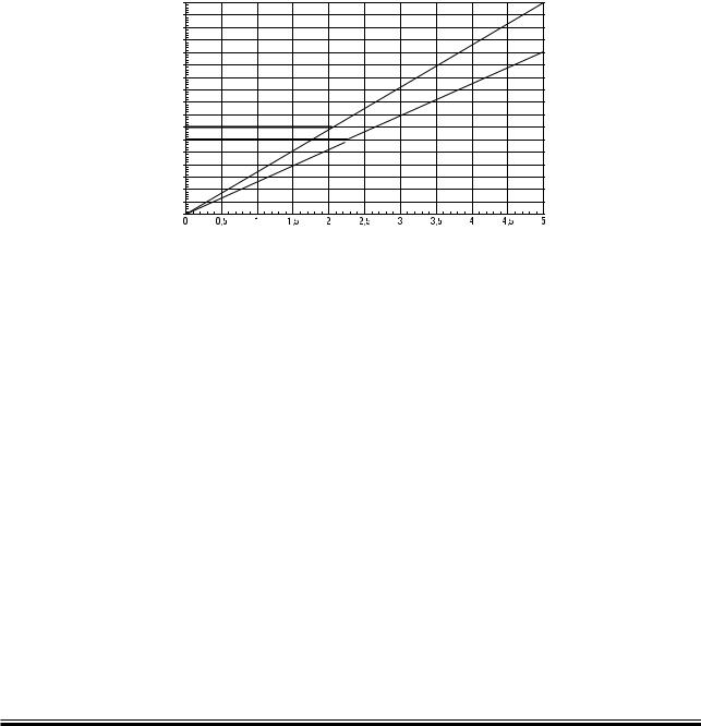
Safe and very lubricating economical control after running-in is obtained with a basic setting according to the formula:
Basic lubricating oil setting = 0.26 g/kWh x S%
with a minimum setting of 0.60 g/kWh, i.e. the setting should be kept constant from about 2.3% sulphur and downwards.


 !LUçTAPEæ
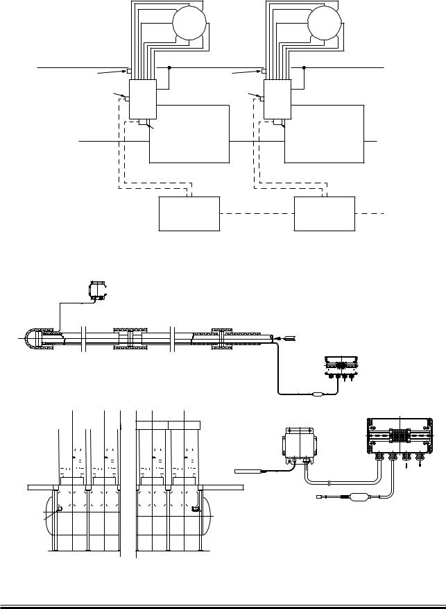

 3OLENOIDæVALVEæ
 4EMPERATUREæSWITCHæ


 4ERMINALæBOXæ


 Terminal box