

The Official Guide to Learning OpenGL, Version 1.1 (Redbook Second Edition)
.pdfOpenGL Programming Guide (Addison-Wesley Publishing Company)
Using glTranslate*() and glRotate*()
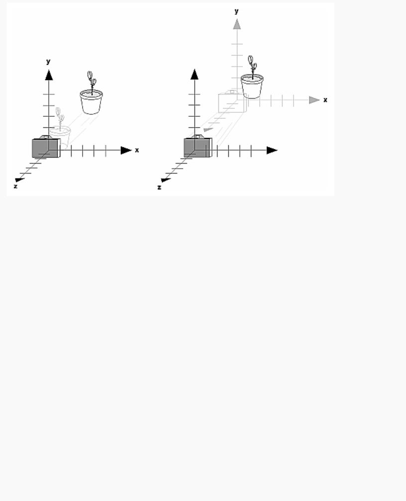
When you use modeling transformation commands to emulate viewing transformations, you're trying to move the viewpoint in a desired way while keeping the objects in the world stationary. Since the viewpoint is initially located at the origin and since objects are often most easily constructed there as well (see Figure 3-9), in general you have to perform some transformation so that the objects can be viewed. Note that, as shown in the figure, the camera initially points down the negative z-axis. (You're seeing the back of the camera.)
Figure 3-9 : Object and Viewpoint at the Origin
In the simplest case, you can move the viewpoint backward, away from the objects; this has the same effect as moving the objects forward, or away from the viewpoint. Remember that by default forward is down the negative z-axis; if you rotate the viewpoint, forward has a different meaning. So, to put 5 units of distance between the viewpoint and the objects by moving the viewpoint, as shown in Figure 3-10, use
glTranslatef(0.0, 0.0, -5.0);
This routine moves the objects in the scene -5 units along the z axis. This is also equivalent to moving the camera +5 units along the z axis.
http://heron.cc.ukans.edu/ebt-bin/nph-dweb/dynaw.../@Generic__BookTextView/6635;cs=fullhtml;pt=1963 (19 of 49) [4/28/2000 9:45:03 PM]
OpenGL Programming Guide (Addison-Wesley Publishing Company)
Figure 3-10 : Separating the Viewpoint and the Object
Now suppose you want to view the objects from the side. Should you issue a rotate command before or after the translate command? If you're thinking in terms of a grand, fixed coordinate system, first imagine both the object and the camera at the origin. You could rotate the object first and then move it away from the camera so that the desired side is visible. Since you know that with the fixed coordinate system approach, commands have to be issued in the opposite order in which they should take effect, you know that you need to write the translate command first in your code and follow it with the rotate command.
Now let's use the local coordinate system approach. In this case, think about moving the object and its local coordinate system away from the origin; then, the rotate command is carried out using the now-translated coordinate system. With this approach, commands are issued in the order in which they're applied, so once again the translate command comes first. Thus, the sequence of transformation commands to produce the desired result is
glTranslatef(0.0, 0.0, -5.0); glRotatef(90.0, 0.0, 1.0, 0.0);
If you're having trouble keeping track of the effect of successive matrix multiplications, try using both the fixed and local coordinate system approaches and see whether one makes more sense to you. Note that with the fixed coordinate system, rotations always occur about the grand origin, whereas with the local coordinate system, rotations occur about the origin of the local system. You might also try using the gluLookAt() utility routine described in the next section.
Using the gluLookAt() Utility Routine
Often, programmers construct a scene around the origin or some other convenient location, then they
http://heron.cc.ukans.edu/ebt-bin/nph-dweb/dynaw.../@Generic__BookTextView/6635;cs=fullhtml;pt=1963 (20 of 49) [4/28/2000 9:45:03 PM]
OpenGL Programming Guide (Addison-Wesley Publishing Company)
want to look at it from an arbitrary point to get a good view of it. As its name suggests, the gluLookAt() utility routine is designed for just this purpose. It takes three sets of arguments, which specify the location of the viewpoint, define a reference point toward which the camera is aimed, and indicate which direction is up. Choose the viewpoint to yield the desired view of the scene. The reference point is typically somewhere in the middle of the scene. (If you've built your scene at the origin, the reference point is probably the origin.) It might be a little trickier to specify the correct up-vector. Again, if you've built some real-world scene at or around the origin and if you've been taking the positive y-axis to point upward, then that's your up-vector for gluLookAt(). However, if you're designing a flight simulator, up is the direction perpendicular to the plane's wings, from the plane toward the sky when the plane is right-side up on the ground.
The gluLookAt() routine is particularly useful when you want to pan across a landscape, for instance. With a viewing volume that's symmetric in both x and y, the (eyex, eyey, eyez) point specified is always in the center of the image on the screen, so you can use a series of commands to move this point slightly, thereby panning across the scene.
void gluLookAt(GLdouble eyex, GLdouble eyey, GLdouble eyez, GLdouble centerx, GLdouble centery, GLdouble centerz, GLdouble upx, GLdouble upy, GLdouble upz);
Defines a viewing matrix and multiplies it to the right of the current matrix. The desired viewpoint is specified by eyex, eyey, and eyez. The centerx, centery, and centerz arguments specify any point along the desired line of sight, but typically they're some point in the center of the scene being looked at. The upx, upy, and upz arguments indicate which direction is up (that is, the direction from the bottom to the top of the viewing volume).
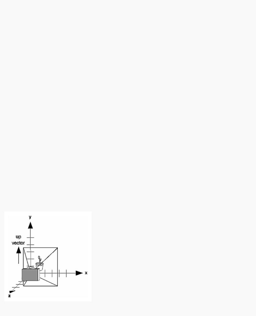
In the default position, the camera is at the origin, is looking down the negative z-axis, and has the positive y-axis as straight up. This is the same as calling
gluLookat (0.0, 0.0, 0.0, 0.0, 0.0, -100.0, 0.0, 1.0, 0.0);
The z value of the reference point is -100.0, but could be any negative z, because the line of sight will remain the same. In this case, you don't actually want to call gluLookAt(), because this is the default (see Figure 3-11) and you are already there! (The lines extending from the camera represent the viewing volume, which indicates its field of view.)
http://heron.cc.ukans.edu/ebt-bin/nph-dweb/dynaw.../@Generic__BookTextView/6635;cs=fullhtml;pt=1963 (21 of 49) [4/28/2000 9:45:03 PM]
OpenGL Programming Guide (Addison-Wesley Publishing Company)
Figure 3-11 : Default Camera Position
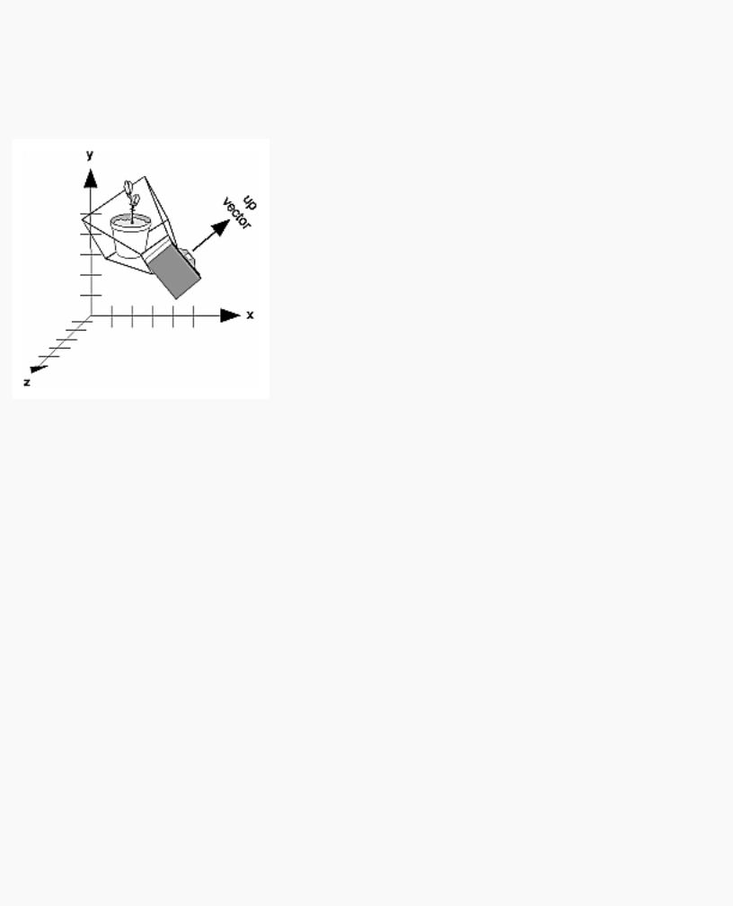
Figure 3-12 shows the effect of a typical gluLookAt() routine. The camera position (eyex, eyey, eyez) is at (4, 2, 1). In this case, the camera is looking right at the model, so the reference point is at (2, 4, -3). An orientation vector of (2, 2, -1) is chosen to rotate the viewpoint to this 45-degree angle.
Figure 3-12 : Using gluLookAt()
So, to achieve this effect, call
gluLookAt(4.0, 2.0, 1.0, 2.0, 4.0, -3.0, 2.0, 2.0, -1.0);
Note that gluLookAt() is part of the Utility Library rather than the basic OpenGL library. This isn't because it's not useful, but because it encapsulates several basic OpenGL commands - specifically, glTranslate*() and glRotate*(). To see this, imagine a camera located at an arbitrary viewpoint and oriented according to a line of sight, both as specified with gluLookAt() and a scene located at the origin. To "undo" what gluLookAt() does, you need to transform the camera so that it sits at the origin and points down the negative z-axis, the default position. A simple translate moves the camera to the origin. You can easily imagine a series of rotations about each of the three axes of a fixed coordinate system that would orient the camera so that it pointed toward negative z values. Since OpenGL allows rotation about an arbitrary axis, you can accomplish any desired rotation of the camera with a single glRotate*() command.
Note: You can have only one active viewing transformation. You cannot try to combine the effects of two viewing transformations, any more than a camera can have two tripods. If you want to change the position of the camera, make sure you call glLoadIdentity() to wipe away the effects of any current viewing transformation.
Advanced
To transform any arbitrary vector so that it's coincident with another arbitrary vector (for instance, the
http://heron.cc.ukans.edu/ebt-bin/nph-dweb/dynaw.../@Generic__BookTextView/6635;cs=fullhtml;pt=1963 (22 of 49) [4/28/2000 9:45:03 PM]

OpenGL Programming Guide (Addison-Wesley Publishing Company)
negative z-axis), you need to do a little mathematics. The axis about which you want to rotate is given by the cross product of the two normalized vectors. To find the angle of rotation, normalize the initial two vectors. The cosine of the desired angle between the vectors is equal to the dot product of the normalized vectors. The angle of rotation around the axis given by the cross product is always between 0 and 180 degrees. (See Appendix E for definitions of cross and dot products.)
Note that computing the angle between two normalized vectors by taking the inverse cosine of their dot product is not very accurate, especially for small angles. But it should work well enough to get you started.
Creating a Custom Utility Routine
Advanced
For some specialized applications, you might want to define your own transformation routine. Since this is rarely done and in any case is a fairly advanced topic, it's left mostly as an exercise for the reader. The following exercises suggest two custom viewing transformations that might be useful.
Try This
●Suppose you're writing a flight simulator and you'd like to display the world from the point of view of the pilot of a plane. The world is described in a coordinate system with the origin on the runway and the plane at coordinates (x, y, z). Suppose further that the plane has some roll, pitch, and heading (these are rotation angles of the plane relative to its center of gravity).
Show that the following routine could serve as the viewing transformation:
void pilotView{GLdouble planex, GLdouble planey, GLdouble planez, GLdouble roll, GLdouble pitch, GLdouble heading)
{
glRotated(roll, 0.0, 0.0, 1.0); glRotated(pitch, 0.0, 1.0, 0.0); glRotated(heading, 1.0, 0.0, 0.0); glTranslated(-planex, -planey, -planez);
}
●Suppose your application involves orbiting the camera around an object that's centered at the origin. In this case, you'd like to specify the viewing transformation by using polar coordinates. Let the distance variable define the radius of the orbit, or how far the camera is from the origin. (Initially, the camera is moved distance units along the positive z-axis.) The azimuth describes the angle of rotation of the camera about the object in the x-y plane, measured from the positive y-axis. Similarly, elevation is the angle of rotation of the camera in the y-z plane, measured from the positive z-axis. Finally, twist represents the rotation of the viewing volume around its line of sight.
Show that the following routine could serve as the viewing transformation:
void polarView{GLdouble distance, GLdouble twist, GLdouble elevation, GLdouble azimuth)
{
http://heron.cc.ukans.edu/ebt-bin/nph-dweb/dynaw.../@Generic__BookTextView/6635;cs=fullhtml;pt=1963 (23 of 49) [4/28/2000 9:45:03 PM]

OpenGL Programming Guide (Addison-Wesley Publishing Company)
glTranslated(0.0, 0.0, -distance); glRotated(-twist, 0.0, 0.0, 1.0); glRotated(-elevation, 1.0, 0.0, 0.0); glRotated(azimuth, 0.0, 0.0, 1.0);
}
Projection Transformations
The previous section described how to compose the desired modelview matrix so that the correct modeling and viewing transformations are applied. This section explains how to define the desired projection matrix, which is also used to transform the vertices in your scene. Before you issue any of the transformation commands described in this section, remember to call
glMatrixMode(GL_PROJECTION); glLoadIdentity();
so that the commands affect the projection matrix rather than the modelview matrix and so that you avoid compound projection transformations. Since each projection transformation command completely describes a particular transformation, typically you don't want to combine a projection transformation with another transformation.
The purpose of the projection transformation is to define a viewing volume, which is used in two ways. The viewing volume determines how an object is projected onto the screen (that is, by using a perspective or an orthographic projection), and it defines which objects or portions of objects are clipped out of the final image. You can think of the viewpoint we've been talking about as existing at one end of the viewing volume. At this point, you might want to reread "A Simple Example: Drawing a Cube" for its overview of all the transformations, including projection transformations.
Perspective Projection
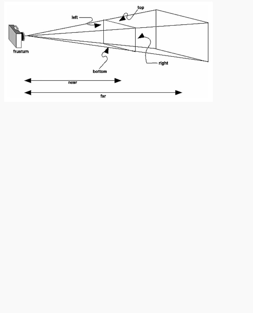
The most unmistakable characteristic of perspective projection is foreshortening: the farther an object is from the camera, the smaller it appears in the final image. This occurs because the viewing volume for a perspective projection is a frustum of a pyramid (a truncated pyramid whose top has been cut off by a plane parallel to its base). Objects that fall within the viewing volume are projected toward the apex of the pyramid, where the camera or viewpoint is. Objects that are closer to the viewpoint appear larger because they occupy a proportionally larger amount of the viewing volume than those that are farther away, in the larger part of the frustum. This method of projection is commonly used for animation, visual simulation, and any other applications that strive for some degree of realism because it's similar to how our eye (or a camera) works.
The command to define a frustum, glFrustum(), calculates a matrix that accomplishes perspective projection and multiplies the current projection matrix (typically the identity matrix) by it. Recall that the viewing volume is used to clip objects that lie outside of it; the four sides of the frustum, its top, and its base correspond to the six clipping planes of the viewing volume, as shown in Figure 3-13. Objects or parts of objects outside these planes are clipped from the final image. Note that glFrustum() doesn't require you to define a symmetric viewing volume.
http://heron.cc.ukans.edu/ebt-bin/nph-dweb/dynaw.../@Generic__BookTextView/6635;cs=fullhtml;pt=1963 (24 of 49) [4/28/2000 9:45:03 PM]
OpenGL Programming Guide (Addison-Wesley Publishing Company)
Figure 3-13 : Perspective Viewing Volume Specified by glFrustum()
void glFrustum(GLdouble left, GLdouble right, GLdouble bottom,
GLdouble top, GLdouble near, GLdouble far);
Creates a matrix for a perspective-view frustum and multiplies the current matrix by it. The frustum's viewing volume is defined by the parameters: (left, bottom, -near) and (right, top, -near) specify the (x, y, z) coordinates of the lower-left and upper-right corners of the near clipping plane; near and far give the distances from the viewpoint to the near and far clipping planes. They should always be positive.
The frustum has a default orientation in three-dimensional space. You can perform rotations or translations on the projection matrix to alter this orientation, but this is tricky and nearly always avoidable.
Advanced
Also, the frustum doesn't have to be symmetrical, and its axis isn't necessarily aligned with the z-axis. For example, you can use glFrustum() to draw a picture as if you were looking through a rectangular window of a house, where the window was above and to the right of you. Photographers use such a viewing volume to create false perspectives. You might use it to have the hardware calculate images at much higher than normal resolutions, perhaps for use on a printer. For example, if you want an image that has twice the resolution of your screen, draw the same picture four times, each time using the frustum to cover the entire screen with one-quarter of the image. After each quarter of the image is rendered, you can read the pixels back to collect the data for the higher-resolution image. (See Chapter 8 for more information about reading pixel data.)
Although it's easy to understand conceptually, glFrustum() isn't intuitive to use. Instead, you might try the Utility Library routine gluPerspective(). This routine creates a viewing volume of the same shape as glFrustum() does, but you specify it in a different way. Rather than specifying corners of the near clipping plane, you specify the angle of the field of view ( &THgr; , or theta, in Figure 3-14) in the y
http://heron.cc.ukans.edu/ebt-bin/nph-dweb/dynaw.../@Generic__BookTextView/6635;cs=fullhtml;pt=1963 (25 of 49) [4/28/2000 9:45:03 PM]

OpenGL Programming Guide (Addison-Wesley Publishing Company)
direction and the aspect ratio of the width to height (x/y). (For a square portion of the screen, the aspect ratio is 1.0.) These two parameters are enough to determine an untruncated pyramid along the line of sight, as shown in Figure 3-14. You also specify the distance between the viewpoint and the near and far clipping planes, thereby truncating the pyramid. Note that gluPerspective() is limited to creating frustums that are symmetric in both the x- and y-axes along the line of sight, but this is usually what you want.
Figure 3-14 : Perspective Viewing Volume Specified by gluPerspective()
void gluPerspective(GLdouble fovy, GLdouble aspect,
GLdouble near, GLdouble far);
Creates a matrix for a symmetric perspective-view frustum and multiplies the current matrix by it. fovy is the angle of the field of view in the x-z plane; its value must be in the range [0.0,180.0]. aspect is the aspect ratio of the frustum, its width divided by its height. near and far values the distances between the viewpoint and the clipping planes, along the negative z-axis. They should always be positive.
Just as with glFrustum(), you can apply rotations or translations to change the default orientation of the viewing volume created by gluPerspective(). With no such transformations, the viewpoint remains at the origin, and the line of sight points down the negative z-axis.
With gluPerspective(), you need to pick appropriate values for the field of view, or the image may look distorted. For example, suppose you're drawing to the entire screen, which happens to be 11 inches high. If you choose a field of view of 90 degrees, your eye has to be about 7.8 inches from the screen for the image to appear undistorted. (This is the distance that makes the screen subtend 90 degrees.) If your eye is farther from the screen, as it usually is, the perspective doesn't look right. If your drawing area occupies less than the full screen, your eye has to be even closer. To get a perfect field of view, figure out how far your eye normally is from the screen and how big the window is, and calculate the angle the window subtends at that size and distance. It's probably smaller than you would guess. Another way to think about it is that a 94-degree field of view with a 35-millimeter camera requires a 20-millimeter lens, which is a very wide-angle lens. (See "Troubleshooting Transformations" for more details on how to
http://heron.cc.ukans.edu/ebt-bin/nph-dweb/dynaw.../@Generic__BookTextView/6635;cs=fullhtml;pt=1963 (26 of 49) [4/28/2000 9:45:03 PM]
OpenGL Programming Guide (Addison-Wesley Publishing Company)
calculate the desired field of view.)
The preceding paragraph mentions inches and millimeters - do these really have anything to do with OpenGL? The answer is, in a word, no. The projection and other transformations are inherently unitless. If you want to think of the near and far clipping planes as located at 1.0 and 20.0 meters, inches, kilometers, or leagues, it's up to you. The only rule is that you have to use a consistent unit of measurement. Then the resulting image is drawn to scale.
Orthographic Projection
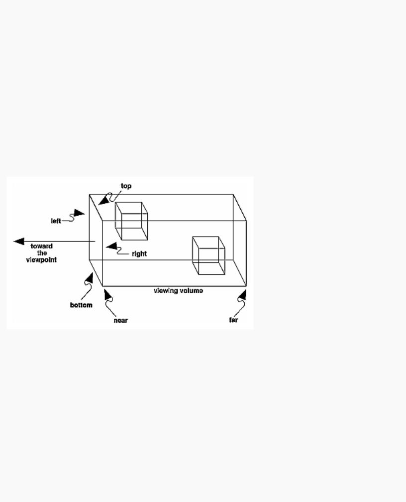
With an orthographic projection, the viewing volume is a rectangular parallelepiped, or more informally, a box (see Figure 3-15). Unlike perspective projection, the size of the viewing volume doesn't change from one end to the other, so distance from the camera doesn't affect how large an object appears. This type of projection is used for applications such as creating architectural blueprints and computer-aided design, where it's crucial to maintain the actual sizes of objects and angles between them as they're projected.
Figure 3-15 : Orthographic Viewing Volume
The command glOrtho() creates an orthographic parallel viewing volume. As with glFrustum(), you specify the corners of the near clipping plane and the distance to the far clipping plane.
void glOrtho(GLdouble left, GLdouble right, GLdouble bottom, GLdouble top, GLdouble near, GLdouble far);
Creates a matrix for an orthographic parallel viewing volume and multiplies the current matrix by it. (left, bottom, -near) and (right, top, -near) are points on the near clipping plane that are mapped to the lower-left and upper-right corners of the viewport window, respectively. (left, bottom, -far) and (right, top, -far) are points on the far clipping plane that are mapped to the same respective corners of the viewport. Both near and far can be positive or negative.
With no other transformations, the direction of projection is parallel to the z-axis, and the viewpoint faces
http://heron.cc.ukans.edu/ebt-bin/nph-dweb/dynaw.../@Generic__BookTextView/6635;cs=fullhtml;pt=1963 (27 of 49) [4/28/2000 9:45:03 PM]
OpenGL Programming Guide (Addison-Wesley Publishing Company)
toward the negative z-axis. Note that this means that the values passed in for far and near are used as negative z values if these planes are in front of the viewpoint, and positive if they're behind the viewpoint.
For the special case of projecting a two-dimensional image onto a two-dimensional screen, use the Utility Library routine gluOrtho2D(). This routine is identical to the three-dimensional version, glOrtho(), except that all the z coordinates for objects in the scene are assumed to lie between -1.0 and 1.0. If you're drawing two-dimensional objects using the two-dimensional vertex commands, all the z coordinates are zero; thus, none of the objects are clipped because of their z values.
void gluOrtho2D(GLdouble left, GLdouble right, GLdouble bottom, GLdouble top);
Creates a matrix for projecting two-dimensional coordinates onto the screen and multiplies the current projection matrix by it. The clipping region is a rectangle with the lower-left corner at (left, bottom) and the upper-right corner at (right, top).
Viewing Volume Clipping
After the vertices of the objects in the scene have been transformed by the modelview and projection matrices, any primitives that lie outside the viewing volume are clipped. The six clipping planes used are those that define the sides and ends of the viewing volume. You can specify additional clipping planes and locate them wherever you choose. (See "Additional Clipping Planes" for information about this relatively advanced topic.) Keep in mind that OpenGL reconstructs the edges of polygons that get clipped.
Viewport Transformation
Recalling the camera analogy, you know that the viewport transformation corresponds to the stage where the size of the developed photograph is chosen. Do you want a wallet-size or a poster-size photograph? Since this is computer graphics, the viewport is the rectangular region of the window where the image is drawn. Figure 3-16 shows a viewport that occupies most of the screen. The viewport is measured in window coordinates, which reflect the position of pixels on the screen relative to the lower-left corner of the window. Keep in mind that all vertices have been transformed by the modelview and projection matrices by this point, and vertices outside the viewing volume have been clipped.
http://heron.cc.ukans.edu/ebt-bin/nph-dweb/dynaw.../@Generic__BookTextView/6635;cs=fullhtml;pt=1963 (28 of 49) [4/28/2000 9:45:03 PM]