

The Official Guide to Learning OpenGL, Version 1.1 (Redbook Second Edition)
.pdfOpenGL Programming Guide (Addison-Wesley Publishing Company)
Figure 3-16 : Viewport Rectangle
Defining the Viewport
The window system, not OpenGL, is responsible for opening a window on the screen. However, by default the viewport is set to the entire pixel rectangle of the window that's opened. You use the glViewport() command to choose a smaller drawing region; for example, you can subdivide the window to create a split-screen effect for multiple views in the same window.
void glViewport(GLint x, GLint y, GLsizei width, GLsizei height);
Defines a pixel rectangle in the window into which the final image is mapped. The (x, y) parameter specifies the lower-left corner of the viewport, and width and height are the size of the viewport rectangle. By default, the initial viewport values are (0, 0, winWidth, winHeight), where winWidth and winHeight are the size of the window.
The aspect ratio of a viewport should generally equal the aspect ratio of the viewing volume. If the two ratios are different, the projected image will be distorted when mapped to the viewport, as shown in Figure 3-17. Note that subsequent changes to the size of the window don't explicitly affect the viewport. Your application should detect window resize events and modify the viewport appropriately.
Figure 3-17 : Mapping the Viewing Volume to the Viewport
In Figure 3-17, the left figure shows a projection that maps a square image onto a square viewport using these routines:
http://heron.cc.ukans.edu/ebt-bin/nph-dweb/dynaw.../@Generic__BookTextView/6635;cs=fullhtml;pt=1963 (29 of 49) [4/28/2000 9:45:03 PM]

OpenGL Programming Guide (Addison-Wesley Publishing Company)
gluPerspective(fovy, 1.0, near, far); glViewport(0, 0, 400, 400);
However, in the right figure, the window has been resized to a nonequilateral rectangular viewport, but the projection is unchanged. The image appears compressed along the x-axis.
gluPerspective(fovy, 1.0, near, far); glViewport (0, 0, 400, 200);
To avoid the distortion, modify the aspect ratio of the projection to match the viewport:
gluPerspective(fovy, 2.0, near, far); glViewport(0, 0, 400, 200);
Try This
Modify an existing program so that an object is drawn twice, in different viewports. You might draw the object with different projection and/or viewing transformations for each viewport. To create two side-by-side viewports, you might issue these commands, along with the appropriate modeling, viewing, and projection transformations:
glViewport (0, 0, sizex/2, sizey);
.
.
.
glViewport (sizex/2, 0, sizex/2, sizey);
The Transformed Depth Coordinate
The depth (z) coordinate is encoded during the viewport transformation (and later stored in the depth buffer). You can scale z values to lie within a desired range with the glDepthRange() command. (Chapter 10 discusses the depth buffer and the corresponding uses for the depth coordinate.) Unlike x and y window coordinates, z window coordinates are treated by OpenGL as though they always range from 0.0 to 1.0.
void glDepthRange(GLclampd near, GLclampd far);
Defines an encoding for z coordinates that's performed during the viewport transformation. The near and far values represent adjustments to the minimum and maximum values that can be stored in the depth buffer. By default, they're 0.0 and 1.0, respectively, which work for most applications.
These parameters are clamped to lie within [0,1].
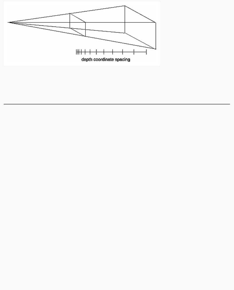
In perspective projection, the transformed depth coordinate (like the x and y coordinates) is subject to perspective division by the w coordinate. As the transformed depth coordinate moves farther away from the near clipping plane, its location becomes increasingly less precise. (See Figure 3-18.)
http://heron.cc.ukans.edu/ebt-bin/nph-dweb/dynaw.../@Generic__BookTextView/6635;cs=fullhtml;pt=1963 (30 of 49) [4/28/2000 9:45:03 PM]
OpenGL Programming Guide (Addison-Wesley Publishing Company)
Figure 3-18 : Perspective Projection and Transformed Depth Coordinates
Therefore, perspective division affects the accuracy of operations which rely upon the transformed depth coordinate, especially depth-buffering, which is used for hidden surface removal.
Troubleshooting Transformations
It's pretty easy to get a camera pointed in the right direction, but in computer graphics, you have to specify position and direction with coordinates and angles. As we can attest, it's all too easy to achieve the well-known black-screen effect. Although any number of things can go wrong, often you get this effect - which results in absolutely nothing being drawn in the window you open on the screen - from incorrectly aiming the "camera" and taking a picture with the model behind you. A similar problem arises if you don't choose a field of view that's wide enough to view your objects but narrow enough so they appear reasonably large.
If you find yourself exerting great programming effort only to create a black window, try these diagnostic steps.
1.Check the obvious possibilities. Make sure your system is plugged in. Make sure you're drawing your objects with a color that's different from the color with which you're clearing the screen. Make sure that whatever states you're using (such as lighting, texturing, alpha blending, logical operations, or antialiasing) are correctly turned on or off, as desired.
2.Remember that with the projection commands, the near and far coordinates measure distance from the viewpoint and that (by default) you're looking down the negative z axis. Thus, if the near value is 1.0 and the far 3.0, objects must have z coordinates between -1.0 and -3.0 in order to be visible. To ensure that you haven't clipped everything out of your scene, temporarily set the near and far clipping planes to some absurdly inclusive values, such as 0.001 and 1000000.0. This alters appearance for operations such as depth-buffering and fog, but it might uncover inadvertently clipped objects.
3.Determine where the viewpoint is, in which direction you're looking, and where your objects are.
http://heron.cc.ukans.edu/ebt-bin/nph-dweb/dynaw.../@Generic__BookTextView/6635;cs=fullhtml;pt=1963 (31 of 49) [4/28/2000 9:45:03 PM]
OpenGL Programming Guide (Addison-Wesley Publishing Company)
It might help to create a real three-dimensional space - using your hands, for instance - to figure these things out.
4.Make sure you know where you're rotating about. You might be rotating about some arbitrary location unless you translated back to the origin first. It's OK to rotate about any point unless you're expecting to rotate about the origin.
5.Check your aim. Use gluLookAt() to aim the viewing volume at your objects. Or draw your objects at or near the origin, and use glTranslate*() as a viewing transformation to move the camera far enough in the z direction only so that the objects fall within the viewing volume. Once you've managed to make your objects visible, try to change the viewing volume incrementally to achieve the exact result you want, as described next.
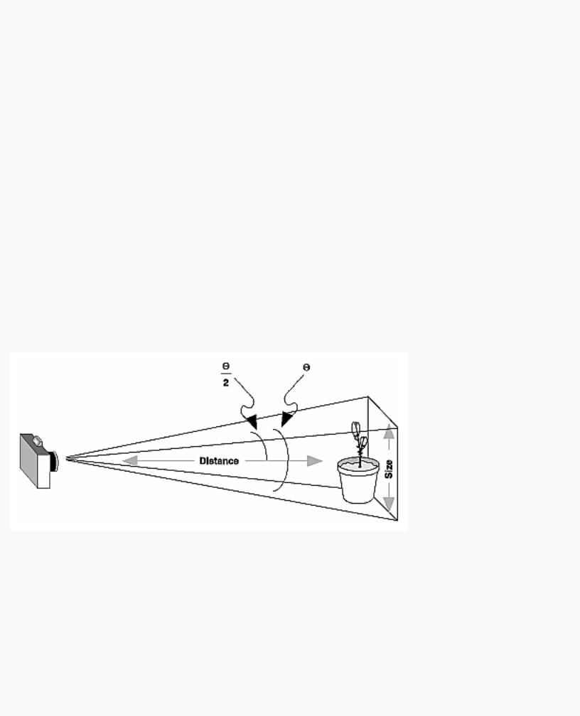
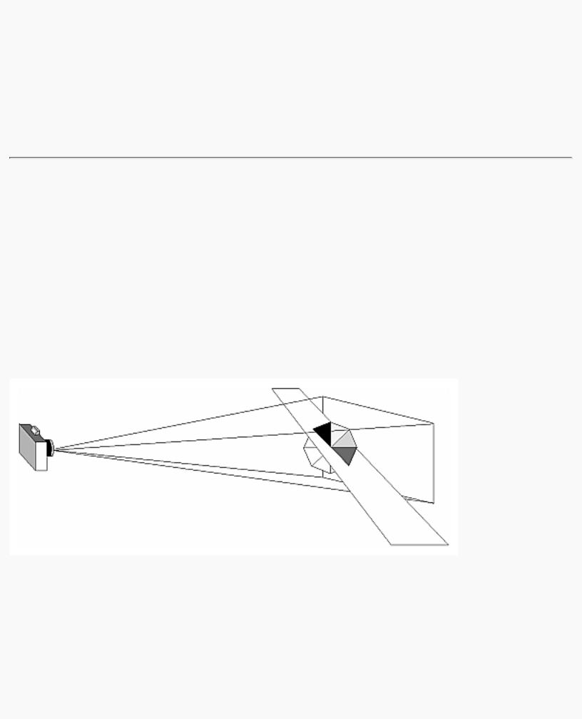
Even after you've aimed the camera in the correct direction and you can see your objects, they might appear too small or too large. If you're using gluPerspective(), you might need to alter the angle defining the field of view by changing the value of the first parameter for this command. You can use trigonometry to calculate the desired field of view given the size of the object and its distance from the viewpoint: The tangent of half the desired angle is half the size of the object divided by the distance to the object (see Figure 3-19). Thus, you can use an arctangent routine to compute half the desired angle. Example 3-3 assumes such a routine, atan2(), which calculates the arctangent given the length of the opposite and adjacent sides of a right triangle. This result then needs to be converted from radians to degrees.
Figure 3-19 : Using Trigonometry to Calculate the Field of View
Example 3-3 : Calculating Field of View
#define PI 3.1415926535
double calculateAngle(double size, double distance)
{
double radtheta, degtheta;
http://heron.cc.ukans.edu/ebt-bin/nph-dweb/dynaw.../@Generic__BookTextView/6635;cs=fullhtml;pt=1963 (32 of 49) [4/28/2000 9:45:03 PM]
OpenGL Programming Guide (Addison-Wesley Publishing Company)
radtheta = 2.0 * atan2 (size/2.0, distance); degtheta = (180.0 * radtheta) / PI;
return (degtheta);
}
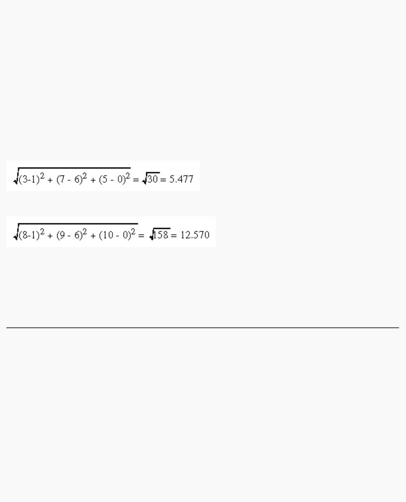
Of course, typically you don't know the exact size of an object, and the distance can only be determined between the viewpoint and a single point in your scene. To obtain a fairly good approximate value, find the bounding box for your scene by determining the maximum and minimum x, y, and z coordinates of all the objects in your scene. Then calculate the radius of a bounding sphere for that box, and use the center of the sphere to determine the distance and the radius to determine the size.
For example, suppose all the coordinates in your object satisfy the equations -1 ≤ x ≤ 3, 5 ≤ y ≤ 7, and -5 ≤ z ≤ 5. Then the center of the bounding box is (1, 6, 0), and the radius of a bounding sphere is the distance from the center of the box to any corner - say (3, 7, 5) - or
If the viewpoint is at (8, 9, 10), the distance between it and the center is
The tangent of the half angle is 5.477 divided by 12.570, which equals 0.4357, so the half angle is 23.54 degrees.
Remember that the field-of-view angle affects the optimal position for the viewpoint, if you're trying to achieve a realistic image. For example, if your calculations indicate that you need a 179-degree field of view, the viewpoint must be a fraction of an inch from the screen to achieve realism. If your calculated field of view is too large, you might need to move the viewpoint farther away from the object.
Manipulating the Matrix Stacks
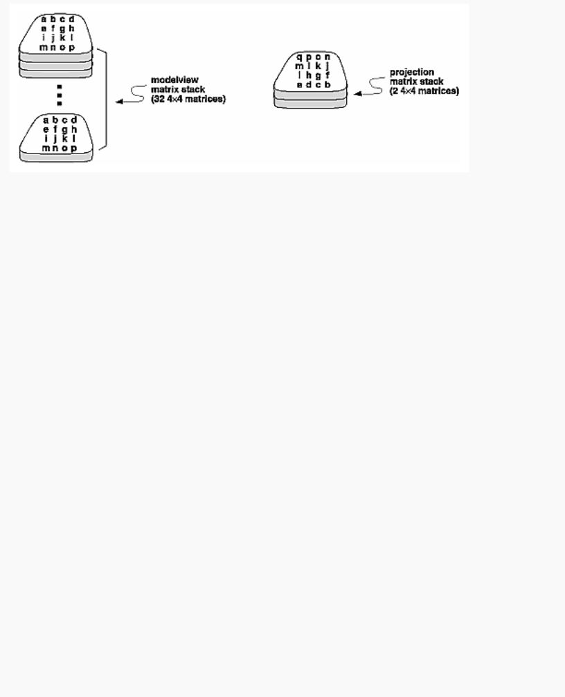
The modelview and projection matrices you've been creating, loading, and multiplying have only been the visible tips of their respective icebergs. Each of these matrices is actually the topmost member of a stack of matrices (see Figure 3-20).
http://heron.cc.ukans.edu/ebt-bin/nph-dweb/dynaw.../@Generic__BookTextView/6635;cs=fullhtml;pt=1963 (33 of 49) [4/28/2000 9:45:03 PM]
OpenGL Programming Guide (Addison-Wesley Publishing Company)
Figure 3-20 : Modelview and Projection Matrix Stacks
A stack of matrices is useful for constructing hierarchical models, in which complicated objects are constructed from simpler ones. For example, suppose you're drawing an automobile that has four wheels, each of which is attached to the car with five bolts. You have a single routine to draw a wheel and another to draw a bolt, since all the wheels and all the bolts look the same. These routines draw a wheel or a bolt in some convenient position and orientation, say centered at the origin with its axis coincident with the z axis. When you draw the car, including the wheels and bolts, you want to call the wheel-drawing routine four times with different transformations in effect each time to position the wheels correctly. As you draw each wheel, you want to draw the bolts five times, each time translated appropriately relative to the wheel.
Suppose for a minute that all you have to do is draw the car body and the wheels. The English description of what you want to do might be something like this:
●Draw the car body. Remember where you are, and translate to the right front wheel. Draw the wheel and throw away the last translation so your current position is back at the origin of the car body. Remember where you are, and translate to the left front wheel....
Similarly, for each wheel, you want to draw the wheel, remember where you are, and successively translate to each of the positions that bolts are drawn, throwing away the transformations after each bolt is drawn.
Since the transformations are stored as matrices, a matrix stack provides an ideal mechanism for doing this sort of successive remembering, translating, and throwing away. All the matrix operations that have been described so far (glLoadMatrix(), glMultMatrix(), glLoadIdentity() and the commands that create specific transformation matrices) deal with the current matrix, or the top matrix on the stack. You can control which matrix is on top with the commands that perform stack operations: glPushMatrix(), which copies the current matrix and adds the copy to the top of the stack, and glPopMatrix(), which discards the top matrix on the stack, as shown in Figure 3-21. (Remember that the current matrix is always the matrix on the top.) In effect, glPushMatrix() means "remember where you are" and glPopMatrix() means "go back to where you were."
http://heron.cc.ukans.edu/ebt-bin/nph-dweb/dynaw.../@Generic__BookTextView/6635;cs=fullhtml;pt=1963 (34 of 49) [4/28/2000 9:45:04 PM]

OpenGL Programming Guide (Addison-Wesley Publishing Company)
Figure 3-21 : Pushing and Popping the Matrix Stack
void glPushMatrix(void);
Pushes all matrices in the current stack down one level. The current stack is determined by glMatrixMode(). The topmost matrix is copied, so its contents are duplicated in both the top and second-from-the-top matrix. If too many matrices are pushed, an error is generated.
void glPopMatrix(void);
Pops the top matrix off the stack, destroying the contents of the popped matrix. What was the second-from-the-top matrix becomes the top matrix. The current stack is determined by glMatrixMode(). If the stack contains a single matrix, calling glPopMatrix() generates an error.
Example 3-4 draws an automobile, assuming the existence of routines that draw the car body, a wheel, and a bolt.
Example 3-4 : Pushing and Popping the Matrix
draw_wheel_and_bolts()
{
long i;
draw_wheel(); for(i=0;i<5;i++){
glPushMatrix();
glRotatef(72.0*i,0.0,0.0,1.0);
glTranslatef(3.0,0.0,0.0); draw_bolt();
glPopMatrix();
}
} |
|
draw_body_and_wheel_and_bolts() |
|
{ |
|
draw_car_body(); |
|
glPushMatrix(); |
|
glTranslatef(40,0,30); |
/*move to first wheel position*/ |
http://heron.cc.ukans.edu/ebt-bin/nph-dweb/dynaw.../@Generic__BookTextView/6635;cs=fullhtml;pt=1963 (35 of 49) [4/28/2000 9:45:04 PM]

OpenGL Programming Guide (Addison-Wesley Publishing Company)
draw_wheel_and_bolts(); glPopMatrix(); glPushMatrix();
glTranslatef(40,0,-30); /*move to 2nd wheel position*/ draw_wheel_and_bolts();
glPopMatrix(); |
|
... |
/*draw last two wheels similarly*/ |
}
This code assumes the wheel and bolt axes are coincident with the z-axis, that the bolts are evenly spaced every 72 degrees, 3 units (maybe inches) from the center of the wheel, and that the front wheels are 40 units in front of and 30 units to the right and left of the car's origin.
A stack is more efficient than an individual matrix, especially if the stack is implemented in hardware. When you push a matrix, you don't need to copy the current data back to the main process, and the hardware may be able to copy more than one element of the matrix at a time. Sometimes you might want to keep an identity matrix at the bottom of the stack so that you don't need to call glLoadIdentity() repeatedly.
The Modelview Matrix Stack
As you've seen earlier in "Viewing and Modeling Transformations," the modelview matrix contains the cumulative product of multiplying viewing and modeling transformation matrices. Each viewing or modeling transformation creates a new matrix that multiplies the current modelview matrix; the result, which becomes the new current matrix, represents the composite transformation. The modelview matrix stack contains at least thirty-two 4 × 4 matrices; initially, the topmost matrix is the identity matrix. Some implementations of OpenGL may support more than thirty-two matrices on the stack. To find the maximum allowable number of matrices, you can use the query command glGetIntegerv(GL_MAX_MODELVIEW_STACK_DEPTH, GLint *params).
The Projection Matrix Stack
The projection matrix contains a matrix for the projection transformation, which describes the viewing volume. Generally, you don't want to compose projection matrices, so you issue glLoadIdentity() before performing a projection transformation. Also for this reason, the projection matrix stack need be only two levels deep; some OpenGL implementations may allow more than two 4 × 4 matrices. To find the stack depth, call glGetIntegerv(GL_MAX_PROJECTION_STACK_DEPTH, GLint *params).
One use for a second matrix in the stack would be an application that needs to display a help window with text in it, in addition to its normal window showing a three-dimensional scene. Since text is most easily positioned with an orthographic projection, you could change temporarily to an orthographic projection, display the help, and then return to your previous projection:
glMatrixMode(GL_PROJECTION); |
|
glPushMatrix(); |
/*save the current projection*/ |
glLoadIdentity(); |
|
glOrtho(...); |
/*set up for displaying help*/ |
http://heron.cc.ukans.edu/ebt-bin/nph-dweb/dynaw.../@Generic__BookTextView/6635;cs=fullhtml;pt=1963 (36 of 49) [4/28/2000 9:45:04 PM]
OpenGL Programming Guide (Addison-Wesley Publishing Company)
display_the_help(); glPopMatrix();
Note that you'd probably have to also change the modelview matrix appropriately.
Advanced
If you know enough mathematics, you can create custom projection matrices that perform arbitrary projective transformations. For example, the OpenGL and its Utility Library have no built-in mechanism for two-point perspective. If you were trying to emulate the drawings in drafting texts, you might need such a projection matrix.
Additional Clipping Planes
In addition to the six clipping planes of the viewing volume (left, right, bottom, top, near, and far), you can define up to six additional clipping planes to further restrict the viewing volume, as shown in Figure 3-22. This is useful for removing extraneous objects in a scene - for example, if you want to display a cutaway view of an object.
Each plane is specified by the coefficients of its equation: Ax+By+Cz+D = 0. The clipping planes are automatically transformed appropriately by modeling and viewing transformations. The clipping volume becomes the intersection of the viewing volume and all half-spaces defined by the additional clipping planes. Remember that polygons that get clipped automatically have their edges reconstructed appropriately by OpenGL.
Figure 3-22 : Additional Clipping Planes and the Viewing Volume
void glClipPlane(GLenum plane, const GLdouble *equation);
Defines a clipping plane. The equation argument points to the four coefficients of the plane equation, Ax+By+Cz+D = 0. All points with eye coordinates (xe, ye, ze, we) that satisfy (A B C
D)M-1 (xe ye ze we)T >= 0 lie in the half-space defined by the plane, where M is the current modelview matrix at the time glClipPlane() is called. All points not in this half-space are clipped
http://heron.cc.ukans.edu/ebt-bin/nph-dweb/dynaw.../@Generic__BookTextView/6635;cs=fullhtml;pt=1963 (37 of 49) [4/28/2000 9:45:04 PM]
OpenGL Programming Guide (Addison-Wesley Publishing Company)
away. The plane argument is GL_CLIP_PLANEi, where i is an integer specifying which of the available clipping planes to define. i is a number between 0 and one less than the maximum number of additional clipping planes.
You need to enable each additional clipping plane you define:
glEnable(GL_CLIP_PLANEi);
You can disable a plane with
glDisable(GL_CLIP_PLANEi);
All implementations of OpenGL must support at least six additional clipping planes, although some implementations may allow more. You can use glGetIntegerv() with GL_MAX_CLIP_PLANES to find how many clipping planes are supported.
Note: Clipping performed as a result of glClipPlane() is done in eye coordinates, not in clip coordinates. This difference is noticeable if the projection matrix is singular (that is, a real projection matrix that flattens three-dimensional coordinates to two-dimensional ones). Clipping performed in eye coordinates continues to take place in three dimensions even when the projection matrix is singular.
A Clipping Plane Code Example
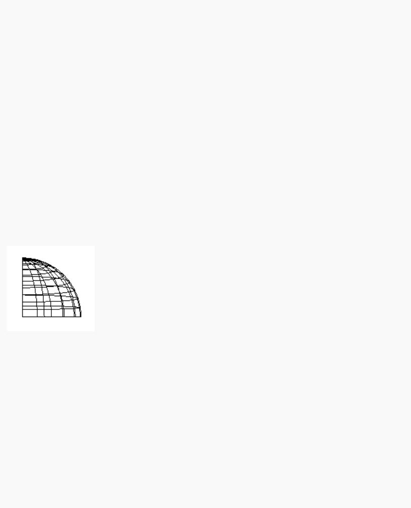
Example 3-5 renders a wireframe sphere with two clipping planes that slice away three-quarters of the original sphere, as shown in Figure 3-23.
Figure 3-23 : Clipped Wireframe Sphere
Example 3-5 : Wireframe Sphere with Two Clipping Planes: clip.c
#include <GL/gl.h> #include <GL/glu.h> #include <GL/glut.h>
void init(void)
{
glClearColor (0.0, 0.0, 0.0, 0.0); glShadeModel (GL_FLAT);
}
http://heron.cc.ukans.edu/ebt-bin/nph-dweb/dynaw.../@Generic__BookTextView/6635;cs=fullhtml;pt=1963 (38 of 49) [4/28/2000 9:45:04 PM]