

The Official Guide to Learning OpenGL, Version 1.1 (Redbook Second Edition)
.pdfOpenGL Programming Guide (Addison-Wesley Publishing Company)
Table 2-1 : Clearing Buffers
Before issuing a command to clear multiple buffers, you have to set the values to which each buffer is to be cleared if you want something other than the default RGBA color, depth value, accumulation color, and stencil index. In addition to the glClearColor() and glClearDepth() commands that set the current values for clearing the color and depth buffers, glClearIndex(), glClearAccum(), and glClearStencil() specify the color index, accumulation color, and stencil index used to clear the corresponding buffers. (See Chapter 4 and Chapter 10 for descriptions of these buffers and their uses.)
OpenGL allows you to specify multiple buffers because clearing is generally a slow operation, since every pixel in the window (possibly millions) is touched, and some graphics hardware allows sets of buffers to be cleared simultaneously. Hardware that doesn't support simultaneous clears performs them sequentially. The difference between
glClear(GL_COLOR_BUFFER_BIT | GL_DEPTH_BUFFER_BIT);
and
glClear(GL_COLOR_BUFFER_BIT); glClear(GL_DEPTH_BUFFER_BIT);
is that although both have the same final effect, the first example might run faster on many machines. It certainly won't run more slowly.
Specifying a Color
With OpenGL, the description of the shape of an object being drawn is independent of the description of its color. Whenever a particular geometric object is drawn, it's drawn using the currently specified coloring scheme. The coloring scheme might be as simple as "draw everything in fire-engine red," or might be as complicated as "assume the object is made out of blue plastic, that there's a yellow spotlight pointed in such and such a direction, and that there's a general low-level reddish-brown light everywhere else." In general, an OpenGL programmer first sets the color or coloring scheme and then draws the objects. Until the color or coloring scheme is changed, all objects are drawn in that color or using that coloring scheme. This method helps OpenGL achieve higher drawing performance than would result if it didn't keep track of the current color.
For example, the pseudocode
set_current_color(red); draw_object(A); draw_object(B); set_current_color(green); set_current_color(blue); draw_object(C);
draws objects A and B in red, and object C in blue. The command on the fourth line that sets the current color to green is wasted.
Coloring, lighting, and shading are all large topics with entire chapters or large sections devoted to them. To draw geometric primitives that can be seen, however, you need some basic knowledge of how to set the current color; this information is provided in the next paragraphs. (See Chapter 4 and Chapter 5 for details on these topics.)
To set a color, use the command glColor3f(). It takes three parameters, all of which are floating-point numbers between 0.0 and 1.0. The parameters are, in order, the red, green, and blue components of the color. You can think of these three values as specifying a "mix" of colors: 0.0 means don't use any of that component, and 1.0 means use all you can of that component. Thus, the code
glColor3f(1.0, 0.0, 0.0);
makes the brightest red the system can draw, with no green or blue components. All zeros makes black; in contrast, all ones makes white. Setting all three components to 0.5 yields gray (halfway between black and white). Here are eight commands and the colors they would set.
glColor3f(0.0, 0.0, 0.0); |
black |
http://heron.cc.ukans.edu/ebt-bin/nph-dweb/dynaw...G/@Generic__BookTextView/1963;cs=fullhtml;pt=622 (3 of 34) [4/28/2000 9:44:39 PM]

OpenGL Programming Guide (Addison-Wesley Publishing Company)
glColor3f(1.0, 0.0, 0.0); |
red |
glColor3f(0.0, 1.0, 0.0); |
green |
glColor3f(1.0, 1.0, 0.0); |
yellow |
glColor3f(0.0, 0.0, 1.0); |
blue |
glColor3f(1.0, 0.0, 1.0); |
magenta |
glColor3f(0.0, 1.0, 1.0); |
cyan |
glColor3f(1.0, 1.0, 1.0); |
white |
You might have noticed earlier that the routine to set the clearing color, glClearColor(), takes four parameters, the first three of which match the parameters for glColor3f(). The fourth parameter is the alpha value; it's covered in detail in "Blending" in Chapter 6. For now, set the fourth parameter of glClearColor() to 0.0, which is its default value.
Forcing Completion of Drawing
As you saw in "OpenGL Rendering Pipeline" in Chapter 1, most modern graphics systems can be thought of as an assembly line. The main central processing unit (CPU) issues a drawing command. Perhaps other hardware does geometric transformations. Clipping is performed, followed by shading and/or texturing. Finally, the values are written into the bitplanes for display. In high-end architectures, each of these operations is performed by a different piece of hardware that's been designed to perform its particular task quickly. In such an architecture, there's no need for the CPU to wait for each drawing command to complete before issuing the next one. While the CPU is sending a vertex down the pipeline, the transformation hardware is working on transforming the last one sent, the one before that is being clipped, and so on. In such a system, if the CPU waited for each command to complete before issuing the next, there could be a huge performance penalty.
In addition, the application might be running on more than one machine. For example, suppose that the main program is running elsewhere (on a machine called the client) and that you're viewing the results of the drawing on your workstation or terminal (the server), which is connected by a network to the client. In that case, it might be horribly inefficient to send each command over the network one at a time, since considerable overhead is often associated with each network transmission. Usually, the client gathers a collection of commands into a single network packet before sending it. Unfortunately, the network code on the client typically has no way of knowing that the graphics program is finished drawing a frame or scene. In the worst case, it waits forever for enough additional drawing commands to fill a packet, and you never see the completed drawing.
For this reason, OpenGL provides the command glFlush(), which forces the client to send the network packet even though it might not be full. Where there is no network and all commands are truly executed immediately on the server, glFlush() might have no effect. However, if you're writing a program that you want to work properly both with and without a network, include a call to glFlush() at the end of each frame or scene. Note that glFlush() doesn't wait for the drawing to complete - it just forces the drawing to begin execution, thereby guaranteeing that all previous commands execute in finite time even if no further rendering commands are executed.
There are other situations where glFlush() is useful.
●Software renderers that build image in system memory and don't want to constantly update the screen.
●Implementations that gather sets of rendering commands to amortize start-up costs. The aforementioned network transmission example is one instance of this.
void glFlush(void);
Forces previously issued OpenGL commands to begin execution, thus guaranteeing that they complete in finite time.
A few commands - for example, commands that swap buffers in double-buffer mode - automatically flush pending commands onto the network before they can occur.
If glFlush() isn't sufficient for you, try glFinish(). This command flushes the network as glFlush() does and then waits for notification from the graphics hardware or network indicating that the drawing is complete in the framebuffer. You might need to use glFinish() if you want to synchronize tasks - for example, to make sure that your three-dimensional rendering is on the screen before you use Display PostScript to draw labels on top of the rendering. Another example would be to ensure that the drawing is complete before it begins to accept user input. After you issue a glFinish() command, your graphics process is blocked until it receives notification from the graphics hardware that the drawing is complete. Keep in mind that excessive use of glFinish() can reduce the performance of your application, especially if you're running over a network, because it requires round-trip communication. If glFlush() is sufficient for your needs, use it instead of glFinish().
void glFinish(void);
Forces all previously issued OpenGL commands to complete. This command doesn't return until all effects from previous commands are fully realized.
Coordinate System Survival Kit
Whenever you initially open a window or later move or resize that window, the window system will send an event to notify you. If you are using GLUT, the notification is automated; whatever routine has been registered to glutReshapeFunc() will be called. You must register a callback function that will
● Reestablish the rectangular region that will be the new rendering canvas
http://heron.cc.ukans.edu/ebt-bin/nph-dweb/dynaw...G/@Generic__BookTextView/1963;cs=fullhtml;pt=622 (4 of 34) [4/28/2000 9:44:39 PM]
OpenGL Programming Guide (Addison-Wesley Publishing Company)
● Define the coordinate system to which objects will be drawn
In Chapter 3 you'll see how to define three-dimensional coordinate systems, but right now, just create a simple, basic two-dimensional coordinate system into which you can draw a few objects. Call glutReshapeFunc(reshape), where reshape() is the following function shown in Example 2-1.
Example 2-1 : Reshape Callback Function
void reshape (int w, int h)
{
glViewport (0, 0, (GLsizei) w, (GLsizei) h); glMatrixMode (GL_PROJECTION); glLoadIdentity ();
gluOrtho2D (0.0, (GLdouble) w, 0.0, (GLdouble) h);
}
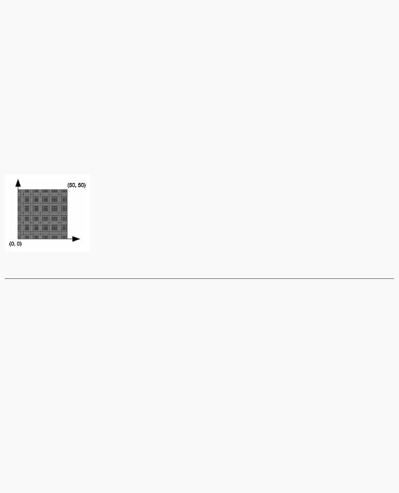
The internals of GLUT will pass this function two arguments: the width and height, in pixels, of the new, moved, or resized window. glViewport() adjusts the pixel rectangle for drawing to be the entire new window. The next three routines adjust the coordinate system for drawing so that the lower-left corner is (0, 0), and the upper-right corner is (w, h) (See Figure 2-1).
To explain it another way, think about a piece of graphing paper. The w and h values in reshape() represent how many columns and rows of squares are on your graph paper. Then you have to put axes on the graph paper. The gluOrtho2D() routine puts the origin, (0, 0), all the way in the lowest, leftmost square, and makes each square represent one unit. Now when you render the points, lines, and polygons in the rest of this chapter, they will appear on this paper in easily predictable squares. (For now, keep all your objects two-dimensional.)
Figure 2-1 : Coordinate System Defined by w = 50, h = 50
Describing Points, Lines, and Polygons
This section explains how to describe OpenGL geometric primitives. All geometric primitives are eventually described in terms of their vertices - coordinates that define the points themselves, the endpoints of line segments, or the corners of polygons. The next section discusses how these primitives are displayed and what control you have over their display.
What Are Points, Lines, and Polygons?
You probably have a fairly good idea of what a mathematician means by the terms point, line, and polygon. The OpenGL meanings are similar, but not quite the same.
One difference comes from the limitations of computer-based calculations. In any OpenGL implementation, floating-point calculations are of finite precision, and they have round-off errors. Consequently, the coordinates of OpenGL points, lines, and polygons suffer from the same problems.
Another more important difference arises from the limitations of a raster graphics display. On such a display, the smallest displayable unit is a pixel, and although pixels might be less than 1/100 of an inch wide, they are still much larger than the mathematician's concepts of infinitely small (for points) or infinitely thin (for lines). When OpenGL performs calculations, it assumes points are represented as vectors of floating-point numbers. However, a point is typically (but not always) drawn as a single pixel, and many different points with slightly different coordinates could be drawn by OpenGL on the same pixel.
Points
A point is represented by a set of floating-point numbers called a vertex. All internal calculations are done as if vertices are three-dimensional. Vertices specified by the user as two-dimensional (that is, with only x and y coordinates) are assigned a z coordinate equal to zero by OpenGL.
Advanced
http://heron.cc.ukans.edu/ebt-bin/nph-dweb/dynaw...G/@Generic__BookTextView/1963;cs=fullhtml;pt=622 (5 of 34) [4/28/2000 9:44:39 PM]
OpenGL Programming Guide (Addison-Wesley Publishing Company)
OpenGL works in the homogeneous coordinates of three-dimensional projective geometry, so for internal calculations, all vertices are represented with four floating-point coordinates (x, y, z, w). If w is different from zero, these coordinates correspond to the Euclidean three-dimensional point (x/w, y/w, z/w). You can specify the w coordinate in OpenGL commands, but that's rarely done. If the w coordinate isn't specified, it's understood to be 1.0. (See Appendix F for more information about homogeneous coordinate systems.)
Lines
In OpenGL, the term line refers to a line segment, not the mathematician's version that extends to infinity in both directions. There are easy ways to specify a connected series of line segments, or even a closed, connected series of segments (see Figure 2-2). In all cases, though, the lines constituting the connected series are specified in terms of the vertices at their endpoints.
Figure 2-2 : Two Connected Series of Line Segments
Polygons
Polygons are the areas enclosed by single closed loops of line segments, where the line segments are specified by the vertices at their endpoints. Polygons are typically drawn with the pixels in the interior filled in, but you can also draw them as outlines or a set of points. (See "Polygon Details.")
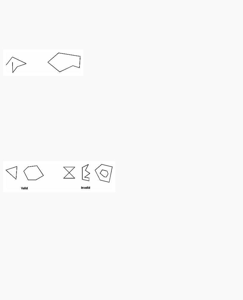
In general, polygons can be complicated, so OpenGL makes some strong restrictions on what constitutes a primitive polygon. First, the edges of OpenGL polygons can't intersect (a mathematician would call a polygon satisfying this condition a simple polygon). Second, OpenGL polygons must be convex, meaning that they cannot have indentations. Stated precisely, a region is convex if, given any two points in the interior, the line segment joining them is also in the interior. See Figure 2-3 for some examples of valid and invalid polygons. OpenGL, however, doesn't restrict the number of line segments making up the boundary of a convex polygon. Note that polygons with holes can't be described. They are nonconvex, and they can't be drawn with a boundary made up of a single closed loop. Be aware that if you present OpenGL with a nonconvex filled polygon, it might not draw it as you expect. For instance, on most systems no more than the convex hull of the polygon would be filled. On some systems, less than the convex hull might be filled.
Figure 2-3 : Valid and Invalid Polygons
The reason for the OpenGL restrictions on valid polygon types is that it's simpler to provide fast polygon-rendering hardware for that restricted class of polygons. Simple polygons can be rendered quickly. The difficult cases are hard to detect quickly. So for maximum performance, OpenGL crosses its fingers and assumes the polygons are simple.
Many real-world surfaces consist of nonsimple polygons, nonconvex polygons, or polygons with holes. Since all such polygons can be formed from unions of simple convex polygons, some routines to build more complex objects are provided in the GLU library. These routines take complex descriptions and tessellate them, or break them down into groups of the simpler OpenGL polygons that can then be rendered. (See "Polygon Tessellation" in Chapter 11 for more information about the tessellation routines.)
Since OpenGL vertices are always three-dimensional, the points forming the boundary of a particular polygon don't necessarily lie on the same plane in space. (Of course, they do in many cases - if all the z coordinates are zero, for example, or if the polygon is a triangle.) If a polygon's vertices don't lie in the same plane, then after various rotations in space, changes in the viewpoint, and projection onto the display screen, the points might no longer form a simple convex polygon. For example, imagine a four-point quadrilateral where the points are slightly out of plane, and look at it almost edge-on. You can get a nonsimple polygon that resembles a bow tie, as shown in Figure 2-4, which isn't guaranteed to be rendered correctly. This situation isn't all that unusual if you approximate curved surfaces by quadrilaterals made of points lying on the true surface. You can always avoid the problem by using triangles, since any three points always lie on a plane.
http://heron.cc.ukans.edu/ebt-bin/nph-dweb/dynaw...G/@Generic__BookTextView/1963;cs=fullhtml;pt=622 (6 of 34) [4/28/2000 9:44:39 PM]
OpenGL Programming Guide (Addison-Wesley Publishing Company)
Figure 2-4 : Nonplanar Polygon Transformed to Nonsimple Polygon
Rectangles
Since rectangles are so common in graphics applications, OpenGL provides a filled-rectangle drawing primitive, glRect*(). You can draw a rectangle as a polygon, as described in "OpenGL Geometric Drawing Primitives," but your particular implementation of OpenGL might have optimized glRect*() for rectangles.
void glRect{sifd}(TYPEx1, TYPEy1, TYPEx2, TYPEy2); void glRect{sifd}v(TYPE*v1, TYPE*v2);
Draws the rectangle defined by the corner points (x1, y1) and (x2, y2). The rectangle lies in the plane z=0 and has sides parallel to the x- and y-axes. If the vector form of the function is used, the corners are given by two pointers to arrays, each of which contains an (x, y) pair.
Note that although the rectangle begins with a particular orientation in three-dimensional space (in the x-y plane and parallel to the axes), you can change this by applying rotations or other transformations. (See Chapter 3 for information about how to do this.)
Curves and Curved Surfaces
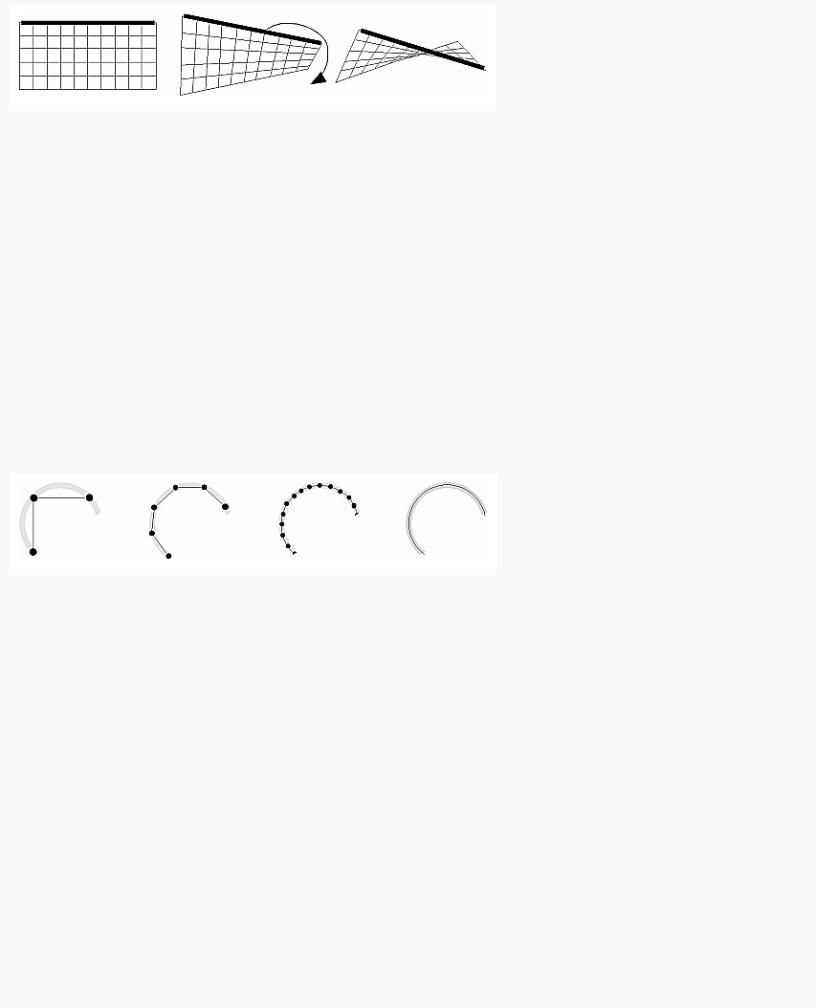
Any smoothly curved line or surface can be approximated - to any arbitrary degree of accuracy - by short line segments or small polygonal regions. Thus, subdividing curved lines and surfaces sufficiently and then approximating them with straight line segments or flat polygons makes them appear curved (see Figure 2-5). If you're skeptical that this really works, imagine subdividing until each line segment or polygon is so tiny that it's smaller than a pixel on the screen.
Figure 2-5 : Approximating Curves
Even though curves aren't geometric primitives, OpenGL does provide some direct support for subdividing and drawing them. (See Chapter 12 for information about how to draw curves and curved surfaces.)
Specifying Vertices
With OpenGL, all geometric objects are ultimately described as an ordered set of vertices. You use the glVertex*() command to specify a vertex.
void glVertex{234}{sifd}[v](TYPEcoords);
Specifies a vertex for use in describing a geometric object. You can supply up to four coordinates (x, y, z, w) for a particular vertex or as few as two (x, y) by selecting the appropriate version of the command. If you use a version that doesn't explicitly specify z or w, z is understood to be 0 and w is understood to be 1. Calls to glVertex*() are only effective between a glBegin() and glEnd() pair.
Example 2-2 provides some examples of using glVertex*().
Example 2-2 : Legal Uses of glVertex*()
glVertex2s(2, 3);
glVertex3d(0.0, 0.0, 3.1415926535898); glVertex4f(2.3, 1.0, -2.2, 2.0);
GLdouble dvect[3] = {5.0, 9.0, 1992.0}; glVertex3dv(dvect);
The first example represents a vertex with three-dimensional coordinates (2, 3, 0). (Remember that if it isn't specified, the z coordinate is understood to be 0.) The coordinates in the second example are (0.0, 0.0, 3.1415926535898) (double-precision floating-point numbers). The third example
http://heron.cc.ukans.edu/ebt-bin/nph-dweb/dynaw...G/@Generic__BookTextView/1963;cs=fullhtml;pt=622 (7 of 34) [4/28/2000 9:44:39 PM]

OpenGL Programming Guide (Addison-Wesley Publishing Company)
represents the vertex with three-dimensional coordinates (1.15, 0.5, -1.1). (Remember that the x, y, and z coordinates are eventually divided by the w coordinate.) In the final example, dvect is a pointer to an array of three double-precision floating-point numbers.
On some machines, the vector form of glVertex*() is more efficient, since only a single parameter needs to be passed to the graphics subsystem. Special hardware might be able to send a whole series of coordinates in a single batch. If your machine is like this, it's to your advantage to arrange your data so that the vertex coordinates are packed sequentially in memory. In this case, there may be some gain in performance by using the vertex array operations of OpenGL. (See "Vertex Arrays.")
OpenGL Geometric Drawing Primitives
Now that you've seen how to specify vertices, you still need to know how to tell OpenGL to create a set of points, a line, or a polygon from those vertices. To do this, you bracket each set of vertices between a call to glBegin() and a call to glEnd(). The argument passed to glBegin() determines what sort of geometric primitive is constructed from the vertices. For example, Example 2-3 specifies the vertices for the polygon shown in Figure 2-6.
Example 2-3 : Filled Polygon
glBegin(GL_POLYGON); glVertex2f(0.0, 0.0); glVertex2f(0.0, 3.0); glVertex2f(4.0, 3.0); glVertex2f(6.0, 1.5); glVertex2f(4.0, 0.0);
glEnd();
Figure 2-6 : Drawing a Polygon or a Set of Points
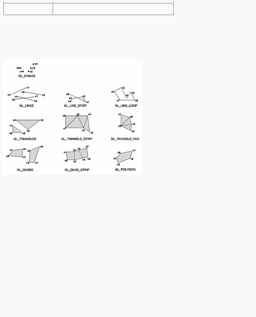
If you had used GL_POINTS instead of GL_POLYGON, the primitive would have been simply the five points shown in Figure 2-6. Table 2-2 in the following function summary for glBegin() lists the ten possible arguments and the corresponding type of primitive.
void glBegin(GLenum mode);
Marks the beginning of a vertex-data list that describes a geometric primitive. The type of primitive is indicated by mode, which can be any of the values shown in Table 2-2.
Table 2-2 : Geometric Primitive Names and Meanings
http://heron.cc.ukans.edu/ebt-bin/nph-dweb/dynaw...G/@Generic__BookTextView/1963;cs=fullhtml;pt=622 (8 of 34) [4/28/2000 9:44:39 PM]
OpenGL Programming Guide (Addison-Wesley Publishing Company)
void glEnd(void);
Marks the end of a vertex-data list.
Figure 2-7 shows examples of all the geometric primitives listed in Table 2-2. The paragraphs that follow the figure describe the pixels that are drawn for each of the objects. Note that in addition to points, several types of lines and polygons are defined. Obviously, you can find many ways to draw the same primitive. The method you choose depends on your vertex data.
Figure 2-7 : Geometric Primitive Types
As you read the following descriptions, assume that n vertices (v0, v1, v2, ... , vn-1) are described between a glBegin() and glEnd() pair.
GL_POINTS |
Draws a point at each of the n vertices. |
GL_LINES |
Draws a series of unconnected line segments. Segments are drawn between v0 and v1, between v2 and v3, and so |
|
on. If n is odd, the last segment is drawn between vn-3 and vn-2, and vn-1 is ignored. |
GL_LINE_STRIP |
Draws a line segment from v0 to v1, then from v1 to v2, and so on, finally drawing the segment from vn-2 to vn-1. |
|
Thus, a total of n-1 line segments are drawn. Nothing is drawn unless n is larger than 1. There are no restrictions on |
|
the vertices describing a line strip (or a line loop); the lines can intersect arbitrarily. |
GL_LINE_LOOP |
Same as GL_LINE_STRIP, except that a final line segment is drawn from vn-1 to v0, completing a loop. |
GL_TRIANGLES |
Draws a series of triangles (three-sided polygons) using vertices v0, v1, v2, then v3, v4, v5, and so on. If n isn't an |
|
exact multiple of 3, the final one or two vertices are ignored. |
GL_TRIANGLE_STRIP |
Draws a series of triangles (three-sided polygons) using vertices v0, v1, v2, then v2, v1, v3 (note the order), then |
|
v2, v3, v4, and so on. The ordering is to ensure that the triangles are all drawn with the same orientation so that the |
|
strip can correctly form part of a surface. Preserving the orientation is important for some operations, such as |
|
culling. (See "Reversing and Culling Polygon Faces") n must be at least 3 for anything to be drawn. |
http://heron.cc.ukans.edu/ebt-bin/nph-dweb/dynaw...G/@Generic__BookTextView/1963;cs=fullhtml;pt=622 (9 of 34) [4/28/2000 9:44:39 PM]
OpenGL Programming Guide (Addison-Wesley Publishing Company)
GL_TRIANGLE_FAN |
Same as GL_TRIANGLE_STRIP, except that the vertices are v0, v1, v2, then v0, v2, v3, then v0, v3, v4, and so on |
|
(see Figure 2-7). |
GL_QUADS |
Draws a series of quadrilaterals (four-sided polygons) using vertices v0, v1, v2, v3, then v4, v5, v6, v7, and so on. |
|
If n isn't a multiple of 4, the final one, two, or three vertices are ignored. |
GL_QUAD_STRIP |
Draws a series of quadrilaterals (four-sided polygons) beginning with v0, v1, v3, v2, then v2, v3, v5, v4, then v4, |
|
v5, v7, v6, and so on (see Figure 2-7). n must be at least 4 before anything is drawn. If n is odd, the final vertex is |
|
ignored. |
GL_POLYGON |
Draws a polygon using the points v0, ... , vn-1 as vertices. n must be at least 3, or nothing is drawn. In addition, the |
|
polygon specified must not intersect itself and must be convex. If the vertices don't satisfy these conditions, the |
|
results are unpredictable. |
Restrictions on Using glBegin() and glEnd()
The most important information about vertices is their coordinates, which are specified by the glVertex*() command. You can also supply additional vertex-specific data for each vertex - a color, a normal vector, texture coordinates, or any combination of these - using special commands. In addition, a few other commands are valid between a glBegin() and glEnd() pair. Table 2-3 contains a complete list of such valid commands.
Table 2-3 : Valid Commands between glBegin() and glEnd()
No other OpenGL commands are valid between a glBegin() and glEnd() pair, and making most other OpenGL calls generates an error. Some vertex array commands, such as glEnableClientState() and glVertexPointer(), when called between glBegin() and glEnd(), have undefined behavior but do not necessarily generate an error. (Also, routines related to OpenGL, such as glX*() routines have undefined behavior between glBegin() and glEnd().) These cases should be avoided, and debugging them may be more difficult.
Note, however, that only OpenGL commands are restricted; you can certainly include other programming-language constructs (except for calls, such as the aforementioned glX*() routines). For example, Example 2-4 draws an outlined circle.
Example 2-4 : Other Constructs between glBegin() and glEnd()
#define PI 3.1415926535898
http://heron.cc.ukans.edu/ebt-bin/nph-dweb/dynaw...G/@Generic__BookTextView/1963;cs=fullhtml;pt=622 (10 of 34) [4/28/2000 9:44:39 PM]

OpenGL Programming Guide (Addison-Wesley Publishing Company)
GLint circle_points = 100; glBegin(GL_LINE_LOOP);
for (i = 0; i < circle_points; i++) { angle = 2*PI*i/circle_points; glVertex2f(cos(angle), sin(angle));
}
glEnd();
Note: This example isn't the most efficient way to draw a circle, especially if you intend to do it repeatedly. The graphics commands used are typically very fast, but this code calculates an angle and calls the sin() and cos() routines for each vertex; in addition, there's the loop overhead. (Another way to calculate the vertices of a circle is to use a GLU routine; see "Quadrics: Rendering Spheres, Cylinders, and Disks" in Chapter 11.) If you need to draw lots of circles, calculate the coordinates of the vertices once and save them in an array and create a display list (see Chapter 7), or use vertex arrays to render them.
Unless they are being compiled into a display list, all glVertex*() commands should appear between some glBegin() and glEnd() combination. (If they appear elsewhere, they don't accomplish anything.) If they appear in a display list, they are executed only if they appear between a glBegin() and a glEnd(). (See Chapter 7 for more information about display lists.)
Although many commands are allowed between glBegin() and glEnd(), vertices are generated only when a glVertex*() command is issued. At the moment glVertex*() is called, OpenGL assigns the resulting vertex the current color, texture coordinates, normal vector information, and so on. To see this, look at the following code sequence. The first point is drawn in red, and the second and third ones in blue, despite the extra color commands.
glBegin(GL_POINTS); |
|
glColor3f(0.0, 1.0, 0.0); |
/* green */ |
glColor3f(1.0, 0.0, 0.0); |
/* red */ |
glVertex(...); |
|
glColor3f(1.0, 1.0, 0.0); |
/* yellow */ |
glColor3f(0.0, 0.0, 1.0); |
/* blue */ |
glVertex(...); |
|
glVertex(...); |
|
glEnd(); |
|
You can use any combination of the 24 versions of the glVertex*() command between glBegin() and glEnd(), although in real applications all the calls in any particular instance tend to be of the same form. If your vertex-data specification is consistent and repetitive (for example, glColor*, glVertex*, glColor*, glVertex*,...), you may enhance your program's performance by using vertex arrays. (See "Vertex Arrays.")
Basic State Management
In the previous section, you saw an example of a state variable, the current RGBA color, and how it can be associated with a primitive. OpenGL maintains many states and state variables. An object may be rendered with lighting, texturing, hidden surface removal, fog, or some other states affecting its appearance.
By default, most of these states are initially inactive. These states may be costly to activate; for example, turning on texture mapping will almost certainly slow down the speed of rendering a primitive. However, the quality of the image will improve and look more realistic, due to the enhanced graphics capabilities.
To turn on and off many of these states, use these two simple commands:
void glEnable(GLenum cap); void glDisable(GLenum cap);
glEnable() turns on a capability, and glDisable() turns it off. There are over 40 enumerated values that can be passed as a parameter to glEnable() or glDisable(). Some examples of these are GL_BLEND (which controls blending RGBA values), GL_DEPTH_TEST (which controls depth comparisons and updates to the depth buffer), GL_FOG (which controls fog), GL_LINE_STIPPLE (patterned lines), GL_LIGHTING (you get the idea), and so forth.
You can also check if a state is currently enabled or disabled.
GLboolean glIsEnabled(GLenum capability)
Returns GL_TRUE or GL_FALSE, depending upon whether the queried capability is currently activated.
The states you have just seen have two settings: on and off. However, most OpenGL routines set values for more complicated state variables. For example, the routine glColor3f() sets three values, which are part of the GL_CURRENT_COLOR state. There are five querying routines used to find out what values are set for many states:
void glGetBooleanv(GLenum pname, GLboolean *params); void glGetIntegerv(GLenum pname, GLint *params);
void glGetFloatv(GLenum pname, GLfloat *params);
http://heron.cc.ukans.edu/ebt-bin/nph-dweb/dynaw...G/@Generic__BookTextView/1963;cs=fullhtml;pt=622 (11 of 34) [4/28/2000 9:44:39 PM]

OpenGL Programming Guide (Addison-Wesley Publishing Company)
void glGetDoublev(GLenum pname, GLdouble *params); void glGetPointerv(GLenum pname, GLvoid **params);
Obtains Boolean, integer, floating-point, double-precision, or pointer state variables. The pname argument is a symbolic constant indicating the state variable to return, and params is a pointer to an array of the indicated type in which to place the returned data. See the tables in Appendix B for the possible values for pname. For example, to get the current RGBA color, a table in Appendix B suggests you use glGetIntegerv(GL_CURRENT_COLOR, params) or glGetFloatv(GL_CURRENT_COLOR, params). A type conversion is performed if necessary to return the desired variable as the requested data type.
These querying routines handle most, but not all, requests for obtaining state information. (See "The Query Commands" in Appendix B for an additional 16 querying routines.)
Displaying Points, Lines, and Polygons
By default, a point is drawn as a single pixel on the screen, a line is drawn solid and one pixel wide, and polygons are drawn solidly filled in. The following paragraphs discuss the details of how to change these default display modes.
Point Details
To control the size of a rendered point, use glPointSize() and supply the desired size in pixels as the argument.
void glPointSize(GLfloat size);
Sets the width in pixels for rendered points; size must be greater than 0.0 and by default is 1.0.
The actual collection of pixels on the screen which are drawn for various point widths depends on whether antialiasing is enabled. (Antialiasing is a technique for smoothing points and lines as they're rendered; see "Antialiasing" in Chapter 6 for more detail.) If antialiasing is disabled (the default), fractional widths are rounded to integer widths, and a screen-aligned square region of pixels is drawn. Thus, if the width is 1.0, the square is 1 pixel by 1 pixel; if the width is 2.0, the square is 2 pixels by 2 pixels, and so on.
With antialiasing enabled, a circular group of pixels is drawn, and the pixels on the boundaries are typically drawn at less than full intensity to give the edge a smoother appearance. In this mode, non-integer widths aren't rounded.
Most OpenGL implementations support very large point sizes. The maximum size for antialiased points is queryable, but the same information is not available for standard, aliased points. A particular implementation, however, might limit the size of standard, aliased points to not less than its maximum antialiased point size, rounded to the nearest integer value. You can obtain this floating-point value by using GL_POINT_SIZE_RANGE with glGetFloatv().
Line Details
With OpenGL, you can specify lines with different widths and lines that are stippled in various ways - dotted, dashed, drawn with alternating dots and dashes, and so on.
Wide Lines
void glLineWidth(GLfloat width);
Sets the width in pixels for rendered lines; width must be greater than 0.0 and by default is 1.0.
The actual rendering of lines is affected by the antialiasing mode, in the same way as for points. (See "Antialiasing" in Chapter 6.) Without antialiasing, widths of 1, 2, and 3 draw lines 1, 2, and 3 pixels wide. With antialiasing enabled, non-integer line widths are possible, and pixels on the boundaries are typically drawn at less than full intensity. As with point sizes, a particular OpenGL implementation might limit the width of nonantialiased lines to its maximum antialiased line width, rounded to the nearest integer value. You can obtain this floating-point value by using GL_LINE_WIDTH_RANGE with glGetFloatv().
Note: Keep in mind that by default lines are 1 pixel wide, so they appear wider on lower-resolution screens. For computer displays, this isn't typically an issue, but if you're using OpenGL to render to a high-resolution plotter, 1-pixel lines might be nearly invisible. To obtain resolution-independent line widths, you need to take into account the physical dimensions of pixels.
Advanced
With nonantialiased wide lines, the line width isn't measured perpendicular to the line. Instead, it's measured in the y direction if the absolute value of the slope is less than 1.0; otherwise, it's measured in the x direction. The rendering of an antialiased line is exactly equivalent to the rendering of a filled rectangle of the given width, centered on the exact line.
Stippled Lines
To make stippled (dotted or dashed) lines, you use the command glLineStipple() to define the stipple pattern, and then you enable line stippling with glEnable().
http://heron.cc.ukans.edu/ebt-bin/nph-dweb/dynaw...G/@Generic__BookTextView/1963;cs=fullhtml;pt=622 (12 of 34) [4/28/2000 9:44:39 PM]