

The Official Guide to Learning OpenGL, Version 1.1 (Redbook Second Edition)
.pdfOpenGL Programming Guide (Addison-Wesley Publishing Company)
0.2, 1.0, 1.0, 300.0, 200.0, 0.0, 0.2, 0.2, 1.0, 200.0, 100.0, 0.0};
Stride allows a vertex array to access its desired data at regular intervals in the array. For example, to reference only the color values in the intertwined array, the following call starts from the beginning of the array (which could also be passed as &intertwined[0]) and jumps ahead 6 * sizeof(GLfloat) bytes, which is the size of both the color and vertex coordinate values. This jump is enough to get to the beginning of the data for the next vertex.
glColorPointer (3, GL_FLOAT, 6 * sizeof(GLfloat), intertwined);
For the vertex coordinate pointer, you need to start from further in the array, at the fourth element of intertwined (remember that C programmers start counting at zero).
glVertexPointer(3, GL_FLOAT,6*sizeof(GLfloat), &intertwined[3]);
Step 3: Dereferencing and Rendering
Until the contents of the vertex arrays are dereferenced, the arrays remain on the client side, and their contents are easily changed. In Step 3, contents of the arrays are obtained, sent down to the server, and then sent down the graphics processing pipeline for rendering.
There are three ways to obtain data: from a single array element (indexed location), from a sequence of array elements, and from an ordered list of array elements.
Dereference a Single Array Element
void glArrayElement(GLint ith)
Obtains the data of one (the ith) vertex for all currently enabled arrays. For the vertex coordinate array, the corresponding command would be glVertex[size][type]v(), where size is one of [2,3,4], and type is one of [s,i,f,d] for GLshort, GLint, GLfloat, and GLdouble respectively. Both size and type were defined by glVertexPointer(). For other enabled arrays, glArrayElement() calls glEdgeFlagv(), glTexCoord[size][type]v(), glColor[size][type]v(), glIndex[type]v(), and glNormal[type]v(). If the vertex coordinate array is enabled, the glVertex*v() routine is executed last, after the execution (if enabled) of up to five corresponding array values.
glArrayElement() is usually called between glBegin() and glEnd(). (If called outside, glArrayElement() sets the current state for all enabled arrays, except for vertex, which has no current state.) In Example 2-10, a triangle is drawn using the third, fourth, and sixth vertices from enabled vertex arrays (again, remember that C programmers begin counting array locations with zero).
Example 2-10 : Using glArrayElement() to Define Colors and Vertices
glEnableClientState (GL_COLOR_ARRAY); glEnableClientState (GL_VERTEX_ARRAY); glColorPointer (3, GL_FLOAT, 0, colors); glVertexPointer (2, GL_INT, 0, vertices);
glBegin(GL_TRIANGLES); glArrayElement (2); glArrayElement (3); glArrayElement (5); glEnd();
When executed, the latter five lines of code has the same effect as
glBegin(GL_TRIANGLES); glColor3fv(colors+(2*3*sizeof(GLfloat)); glVertex3fv(vertices+(2*2*sizeof(GLint)); glColor3fv(colors+(3*3*sizeof(GLfloat)); glVertex3fv(vertices+(3*2*sizeof(GLint)); glColor3fv(colors+(5*3*sizeof(GLfloat)); glVertex3fv(vertices+(5*2*sizeof(GLint)); glEnd();
Since glArrayElement() is only a single function call per vertex, it may reduce the number of function calls, which increases overall performance.
Be warned that if the contents of the array are changed between glBegin() and glEnd(), there is no guarantee that you will receive original data or changed data for your requested element. To be safe, don't change the contents of any array element which might be accessed until the primitive is completed.
Dereference a List of Array Elements
glArrayElement() is good for randomly "hopping around" your data arrays. A similar routine, glDrawElements(), is good for hopping around your data arrays in a more orderly manner.
http://heron.cc.ukans.edu/ebt-bin/nph-dweb/dynaw...G/@Generic__BookTextView/1963;cs=fullhtml;pt=622 (23 of 34) [4/28/2000 9:44:40 PM]
OpenGL Programming Guide (Addison-Wesley Publishing Company)
void glDrawElements(GLenum mode, GLsizei count, GLenum type, void *indices);
Defines a sequence of geometric primitives using count number of elements, whose indices are stored in the array indices. type must be one of GL_UNSIGNED_BYTE, GL_UNSIGNED_SHORT, or GL_UNSIGNED_INT, indicating the data type of the indices array. mode specifies what kind of primitives are constructed and is one of the same values that is accepted by glBegin(); for example, GL_POLYGON, GL_LINE_LOOP, GL_LINES, GL_POINTS, and so on.
The effect of glDrawElements() is almost the same as this command sequence:
int i;
glBegin (mode);
for (i = 0; i < count; i++) glArrayElement(indices[i]);
glEnd();
glDrawElements() additionally checks to make sure mode, count, and type are valid. Also, unlike the preceding sequence, executing glDrawElements() leaves several states indeterminate. After execution of glDrawElements(), current RGB color, color index, normal coordinates, texture coordinates, and edge flag are indeterminate if the corresponding array has been enabled.
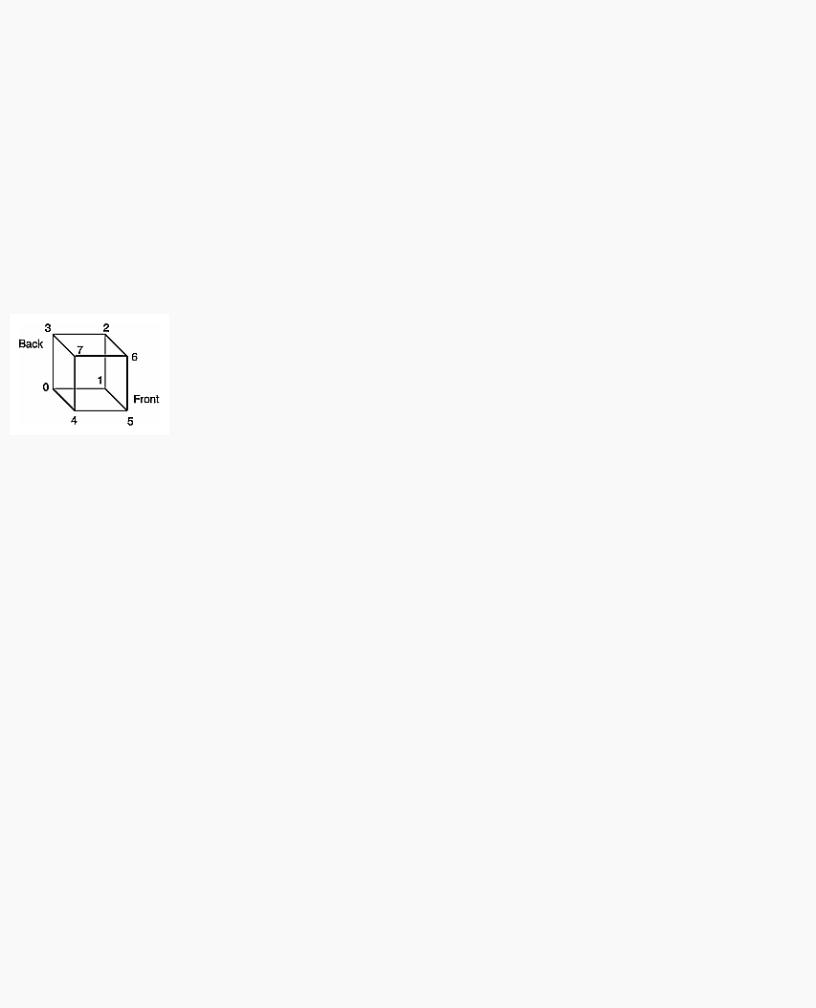
With glDrawElements(), the vertices for each face of the cube can be placed in an array of indices. Example 2-11 shows two ways to use glDrawElements() to render the cube. Figure 2-15 shows the numbering of the vertices used in Example 2-11.
Figure 2-15 : Cube with Numbered Vertices
Example 2-11 : Two Ways to Use glDrawElements()
static GLubyte frontIndices = {4, 5, 6, 7}; static GLubyte rightIndices = {1, 2, 6, 5}; static GLubyte bottomIndices = {0, 1, 5, 4}; static GLubyte backIndices = {0, 3, 2, 1}; static GLubyte leftIndices = {0, 4, 7, 3}; static GLubyte topIndices = {2, 3, 7, 6};
glDrawElements(GL_QUADS, 4, GL_UNSIGNED_BYTE, frontIndices); glDrawElements(GL_QUADS, 4, GL_UNSIGNED_BYTE, rightIndices); glDrawElements(GL_QUADS, 4, GL_UNSIGNED_BYTE, bottomIndices); glDrawElements(GL_QUADS, 4, GL_UNSIGNED_BYTE, backIndices); glDrawElements(GL_QUADS, 4, GL_UNSIGNED_BYTE, leftIndices); glDrawElements(GL_QUADS, 4, GL_UNSIGNED_BYTE, topIndices);
Or better still, crunch all the indices together:
static GLubyte allIndices = {4, 5, 6, 7, 1, 2, 6, 5, 0, 1, 5, 4, 0, 3, 2, 1, 0, 4, 7, 3, 2, 3, 7, 6};
glDrawElements(GL_QUADS, 24, GL_UNSIGNED_BYTE, allIndices);
Note: It is an error to encapsulate glDrawElements() between a glBegin()/glEnd() pair.
With both glArrayElement() and glDrawElements(), it is also possible that your OpenGL implementation caches recently processed vertices, allowing your application to "share" or "reuse" vertices. Take the aforementioned cube, for example, which has six faces (polygons) but only eight vertices. Each vertex is used by exactly three faces. Without glArrayElement() or glDrawElements(), rendering all six faces would require processing twenty-four vertices, even though sixteen vertices would be redundant. Your implementation of OpenGL may be able to minimize redundancy and process as few as eight vertices. (Reuse of vertices may be limited to all vertices within a single glDrawElements() call or, for glArrayElement(), within one glBegin()/glEnd() pair.)
Dereference a Sequence of Array Elements
http://heron.cc.ukans.edu/ebt-bin/nph-dweb/dynaw...G/@Generic__BookTextView/1963;cs=fullhtml;pt=622 (24 of 34) [4/28/2000 9:44:40 PM]

OpenGL Programming Guide (Addison-Wesley Publishing Company)
While glArrayElement() and glDrawElements() "hop around" your data arrays, glDrawArrays() plows straight through them.
void glDrawArrays(GLenum mode, GLint first, GLsizei count);
Constructs a sequence of geometric primitives using array elements starting at first and ending at first+count-1 of each enabled array. mode specifies what kinds of primitives are constructed and is one of the same values accepted by glBegin(); for example, GL_POLYGON, GL_LINE_LOOP, GL_LINES, GL_POINTS, and so on.
The effect of glDrawArrays() is almost the same as this command sequence:
int i;
glBegin (mode);
for (i = 0; i < count; i++) glArrayElement(first + i);
glEnd();
As is the case with glDrawElements(), glDrawArrays() also performs error checking on its parameter values and leaves the current RGB color, color index, normal coordinates, texture coordinates, and edge flag with indeterminate values if the corresponding array has been enabled.
Try This
● Change the icosahedron drawing routine in Example 2-13 to use vertex arrays.
Interleaved Arrays
Advanced
Earlier in this chapter (in "Stride"), the special case of interleaved arrays was examined. In that section, the array intertwined, which interleaves RGB color and 3D vertex coordinates, was accessed by calls to glColorPointer() and glVertexPointer(). Careful use of stride helped properly specify the arrays.
static GLfloat intertwined[] |
= |
|
|
||
{1.0, 0.2, |
1.0, |
100.0, |
100.0, |
0.0, |
|
1.0, 0.2, |
0.2, |
0.0, 200.0, |
0.0, |
||
1.0, 1.0, |
0.2, |
100.0, |
300.0, |
0.0, |
|
0.2, 1.0, |
0.2, |
200.0, |
300.0, |
0.0, |
|
0.2, 1.0, |
1.0, |
300.0, |
200.0, |
0.0, |
|
0.2, 0.2, |
1.0, |
200.0, |
100.0, |
0.0}; |
|
There is also a behemoth routine, glInterleavedArrays(), that can specify several vertex arrays at once. glInterleavedArrays() also enables and disables the appropriate arrays (so it combines both Steps 1 and 2). The array intertwined exactly fits one of the fourteen data interleaving configurations supported by glInterleavedArrays(). So to specify the contents of the array intertwined into the RGB color and vertex arrays and enable both arrays, call
glInterleavedArrays (GL_C3F_V3F, 0, intertwined);
This call to glInterleavedArrays() enables the GL_COLOR_ARRAY and GL_VERTEX_ARRAY arrays. It disables the GL_INDEX_ARRAY, GL_TEXTURE_COORD_ARRAY, GL_NORMAL_ARRAY, and GL_EDGE_FLAG_ARRAY.
This call also has the same effect as calling glColorPointer() and glVertexPointer() to specify the values for six vertices into each array. Now you are ready for Step 3: Calling glArrayElement(), glDrawElements(), or glDrawArrays() to dereference array elements.
void glInterleavedArrays(GLenum format, GLsizei stride, void *pointer)
Initializes all six arrays, disabling arrays that are not specified in format, and enabling the arrays that are specified. format is one of 14 symbolic constants, which represent 14 data configurations; Table 2-5 displays format values. stride specifies the byte offset between consecutive vertexes. If stride is 0, the vertexes are understood to be tightly packed in the array. pointer is the memory address of the first coordinate of the first vertex in the array.
Note that glInterleavedArrays() does not support edge flags.
The mechanics of glInterleavedArrays() are intricate and require reference to Example 2-12 and Table 2-5. In that example and table, you'll see et, ec, and en, which are the boolean values for the enabled or disabled texture coordinate, color, and normal arrays, and you'll see st, sc, and sv, which are the sizes (number of components) for the texture coordinate, color, and vertex arrays. tc is the data type for RGBA color, which is the only array that can have non-float interleaved values. pc, pn, and pv are the calculated strides for jumping over individual color, normal, and vertex values, and s is the stride (if one is not specified by the user) to jump from one array element to the next.
The effect of glInterleavedArrays() is the same as calling the command sequence in Example 2-12 with many values defined in Table 2-5. All pointer arithmetic is performed in units of sizeof(GL_UNSIGNED_BYTE).
Example 2-12 : Effect of glInterleavedArrays(format, stride, pointer)
int str;
/* set et, ec, en, st, sc, sv, tc, pc, pn, pv, and s
http://heron.cc.ukans.edu/ebt-bin/nph-dweb/dynaw...G/@Generic__BookTextView/1963;cs=fullhtml;pt=622 (25 of 34) [4/28/2000 9:44:40 PM]
OpenGL Programming Guide (Addison-Wesley Publishing Company)
* as a function of Table 2-5 and the value of format */
str = stride; if (str == 0) str = s;
glDisableClientState(GL_EDGE_FLAG_ARRAY); glDisableClientState(GL_INDEX_ARRAY);
if (et) { glEnableClientState(GL_TEXTURE_COORD_ARRAY); glTexCoordPointer(st, GL_FLOAT, str, pointer);
}
else glDisableClientState(GL_TEXTURE_COORD_ARRAY);
if (ec) { glEnableClientState(GL_COLOR_ARRAY); glColorPointer(sc, tc, str, pointer+pc);
}
else glDisableClientState(GL_COLOR_ARRAY);
if (en) { glEnableClientState(GL_NORMAL_ARRAY); glNormalPointer(GL_FLOAT, str, pointer+pn);
}
else glDisableClientState(GL_NORMAL_ARRAY);
glEnableClientState(GL_VERTEX_ARRAY); glVertexPointer(sv, GL_FLOAT, str, pointer+pv);
In Table 2-5, T and F are True and False. f is sizeof(GL_FLOAT). c is 4 times sizeof(GL_UNSIGNED_BYTE), rounded up to the nearest multiple of f.
Table 2-5 : (continued) Variables that Direct glInterleavedArrays()
http://heron.cc.ukans.edu/ebt-bin/nph-dweb/dynaw...G/@Generic__BookTextView/1963;cs=fullhtml;pt=622 (26 of 34) [4/28/2000 9:44:40 PM]
OpenGL Programming Guide (Addison-Wesley Publishing Company)
Start by learning the simpler formats, GL_V2F, GL_V3F, and GL_C3F_V3F. If you use any of the formats with C4UB, you may have to use a struct data type or do some delicate type casting and pointer math to pack four unsigned bytes into a single 32-bit word.
For some OpenGL implementations, use of interleaved arrays may increase application performance. With an interleaved array, the exact layout of your data is known. You know your data is tightly packed and may be accessed in one chunk. If interleaved arrays are not used, the stride and size information has to be examined to detect whether data is tightly packed.
Note: glInterleavedArrays() only enables and disables vertex arrays and specifies values for the vertex-array data. It does not render anything. You must still complete Step 3 and call glArrayElement(), glDrawElements(), or glDrawArrays() to dereference the pointers and render graphics.
Attribute Groups
In "Basic State Management," you saw how to set or query an individual state or state variable. Well, you can also save and restore the values of a collection of related state variables with a single command.
OpenGL groups related state variables into an attribute group. For example, the GL_LINE_BIT attribute consists of five state variables: the line width, the GL_LINE_STIPPLE enable status, the line stipple pattern, the line stipple repeat counter, and the GL_LINE_SMOOTH enable status. (See "Antialiasing" in Chapter 6.) With the commands glPushAttrib() and glPopAttrib(), you can save and restore all five state variables, all at once.
Some state variables are in more than one attribute group. For example, the state variable, GL_CULL_FACE, is part of both the polygon and the enable attribute groups.
In OpenGL Version 1.1, there are now two different attribute stacks. In addition to the original attribute stack (which saves the values of server state variables), there is also a client attribute stack, accessible by the commands glPushClientAttrib() and glPopClientAttrib().
In general, it's faster to use these commands than to get, save, and restore the values yourself. Some values might be maintained in the hardware, and getting them might be expensive. Also, if you're operating on a remote client, all the attribute data has to be transferred across the network connection and back as it is obtained, saved, and restored. However, your OpenGL implementation keeps the attribute stack on the server, avoiding unnecessary network delays.
There are about twenty different attribute groups, which can be saved and restored by glPushAttrib() and glPopAttrib(). There are two client attribute groups, which can be saved and restored by glPushClientAttrib() and glPopClientAttrib(). For both server and client, the attributes are stored on a stack, which has a depth of at least 16 saved attribute groups. (The actual stack depths for your implementation can be obtained using GL_MAX_ATTRIB_STACK_DEPTH and GL_MAX_CLIENT_ATTRIB_STACK_DEPTH with glGetIntegerv().) Pushing a full stack or popping an empty one generates an error.
(See the tables in Appendix B to find out exactly which attributes are saved for particular mask values; that is, which attributes are in a particular attribute group.)
void glPushAttrib(GLbitfield mask); void glPopAttrib(void);
glPushAttrib() saves all the attributes indicated by bits in mask by pushing them onto the attribute stack. glPopAttrib() restores the values of those state variables that were saved with the last glPushAttrib(). Table 2-7 lists the possible mask bits that can be logically ORed together to save any combination of attributes. Each bit corresponds to a collection of individual state variables. For example, GL_LIGHTING_BIT refers to all the state variables related to lighting, which include the current material color, the ambient, diffuse, specular, and emitted light, a list of the lights that are enabled, and the directions of the spotlights. When glPopAttrib() is called, all those variables are restored.
http://heron.cc.ukans.edu/ebt-bin/nph-dweb/dynaw...G/@Generic__BookTextView/1963;cs=fullhtml;pt=622 (27 of 34) [4/28/2000 9:44:40 PM]
OpenGL Programming Guide (Addison-Wesley Publishing Company)
The special mask, GL_ALL_ATTRIB_BITS, is used to save and restore all the state variables in all the attribute groups.
Table 2-6 : (continued) Attribute Groups
void glPushClientAttrib(GLbitfield mask); void glPopClientAttrib(void);
glPushClientAttrib() saves all the attributes indicated by bits in mask by pushing them onto the client attribute stack. glPopClientAttrib() restores the values of those state variables that were saved with the last glPushClientAttrib(). Table 2-7 lists the possible mask bits that can
http://heron.cc.ukans.edu/ebt-bin/nph-dweb/dynaw...G/@Generic__BookTextView/1963;cs=fullhtml;pt=622 (28 of 34) [4/28/2000 9:44:40 PM]

OpenGL Programming Guide (Addison-Wesley Publishing Company)
be logically ORed together to save any combination of client attributes.
There are two client attribute groups, feedback and select, that cannot be saved or restored with the stack mechanism.
Table 2-7 : Client Attribute Groups
Some Hints for Building Polygonal Models of Surfaces
Following are some techniques that you might want to use as you build polygonal approximations of surfaces. You might want to review this section after you've read Chapter 5 on lighting and Chapter 7 on display lists. The lighting conditions affect how models look once they're drawn, and some of the following techniques are much more efficient when used in conjunction with display lists. As you read these techniques, keep in mind that when lighting calculations are enabled, normal vectors must be specified to get proper results.
Constructing polygonal approximations to surfaces is an art, and there is no substitute for experience. This section, however, lists a few pointers that might make it a bit easier to get started.
●Keep polygon orientations consistent. Make sure that when viewed from the outside, all the polygons on the surface are oriented in the same direction (all clockwise or all counterclockwise). Consistent orientation is important for polygon culling and two-sided lighting. Try to get this right the first time, since it's excruciatingly painful to fix the problem later. (If you use glScale*() to reflect geometry around some axis of symmetry, you might change the orientation with glFrontFace() to keep the orientations consistent.)
●When you subdivide a surface, watch out for any nontriangular polygons. The three vertices of a triangle are guaranteed to lie on a plane; any polygon with four or more vertices might not. Nonplanar polygons can be viewed from some orientation such that the edges cross each other, and OpenGL might not render such polygons correctly.
●There's always a trade-off between the display speed and the quality of the image. If you subdivide a surface into a small number of polygons, it renders quickly but might have a jagged appearance; if you subdivide it into millions of tiny polygons, it probably looks good but might take a long time to render. Ideally, you can provide a parameter to the subdivision routines that indicates how fine a subdivision you want, and if the object is farther from the eye, you can use a coarser subdivision. Also, when you subdivide, use large polygons where the surface is relatively flat, and small polygons in regions of high curvature.
●For high-quality images, it's a good idea to subdivide more on the silhouette edges than in the interior. If the surface is to be rotated relative to the eye, this is tougher to do, since the silhouette edges keep moving. Silhouette edges occur where the normal vectors are perpendicular to the vector from the surface to the viewpoint - that is, when their vector dot product is zero. Your subdivision algorithm might choose to subdivide more if this dot product is near zero.
●Try to avoid T-intersections in your models (see Figure 2-16). As shown, there's no guarantee that the line segments AB and BC lie on exactly the same pixels as the segment AC. Sometimes they do, and sometimes they don't, depending on the transformations and orientation. This can cause cracks to appear intermittently in the surface.
http://heron.cc.ukans.edu/ebt-bin/nph-dweb/dynaw...G/@Generic__BookTextView/1963;cs=fullhtml;pt=622 (29 of 34) [4/28/2000 9:44:40 PM]

OpenGL Programming Guide (Addison-Wesley Publishing Company)
Figure 2-16 : Modifying an Undesirable T-intersection
●If you're constructing a closed surface, make sure to use exactly the same numbers for coordinates at the beginning and end of a closed loop, or you can get gaps and cracks due to numerical round-off. Here's a two-dimensional example of bad code:
/* don't use this code */ #define PI 3.14159265 #define EDGES 30
/* draw a circle */ glBegin(GL_LINE_STRIP);
for (i = 0; i <= EDGES; i++) glVertex2f(cos((2*PI*i)/EDGES), sin((2*PI*i)/EDGES));
glEnd();
The edges meet exactly only if your machine manages to calculate the sine and cosine of 0 and of (2*PI*EDGES/EDGES) and gets exactly the same values. If you trust the floating-point unit on your machine to do this right, the authors have a bridge they'd like to sell you.... To correct the code, make sure that when i == EDGES, you use 0 for the sine and cosine, not 2*PI*EDGES/EDGES. (Or simpler still, use GL_LINE_LOOP instead of GL_LINE_STRIP, and change the loop termination condition to i < EDGES.)
An Example: Building an Icosahedron
To illustrate some of the considerations that arise in approximating a surface, let's look at some example code sequences. This code concerns the vertices of a regular icosahedron (which is a Platonic solid composed of twenty faces that span twelve vertices, each face of which is an equilateral triangle). An icosahedron can be considered a rough approximation for a sphere. Example 2-13 defines the vertices and triangles making up an icosahedron and then draws the icosahedron.
Example 2-13 : Drawing an Icosahedron
#define X .525731112119133606 #define Z .850650808352039932
static |
GLfloat vdata[12][3] = |
{ |
|
{-X, 0.0, Z}, {X, 0.0, Z}, |
{-X, 0.0, -Z}, {X, 0.0, -Z}, |
||
{0.0, Z, X}, |
{0.0, Z, -X}, |
{0.0, -Z, X}, {0.0, -Z, -X}, |
|
{Z, |
X, 0.0}, |
{-Z, X, 0.0}, |
{Z, -X, 0.0}, {-Z, -X, 0.0} |
};
static GLuint tindices[20][3] = {
{0,4,1}, {0,9,4}, {9,5,4}, {4,5,8}, {4,8,1}, {8,10,1}, {8,3,10}, {5,3,8}, {5,2,3}, {2,7,3}, {7,10,3}, {7,6,10}, {7,11,6}, {11,0,6}, {0,1,6}, {6,1,10}, {9,0,11}, {9,11,2}, {9,2,5}, {7,2,11} };
int i;
glBegin(GL_TRIANGLES);
for (i = 0; i < 20; i++) {
/* color information here */ glVertex3fv(&vdata[tindices[i][0]][0]); glVertex3fv(&vdata[tindices[i][1]][0]); glVertex3fv(&vdata[tindices[i][2]][0]);
}
glEnd();
The strange numbers X and Z are chosen so that the distance from the origin to any of the vertices of the icosahedron is 1.0. The coordinates of the twelve vertices are given in the array vdata[][], where the zeroth vertex is {- &Xgr; , 0.0, &Zgr; }, the first is {X, 0.0, Z}, and so on. The array tindices[][] tells how to link the vertices to make triangles. For example, the first triangle is made from the zeroth, fourth, and first vertex. If you take the vertices for triangles in the order given, all the triangles have the same orientation.
The line that mentions color information should be replaced by a command that sets the color of the ith face. If no code appears here, all faces are drawn in the same color, and it'll be impossible to discern the three-dimensional quality of the object. An alternative to explicitly specifying colors is to define surface normals and use lighting, as described in the next subsection.
Note: In all the examples described in this section, unless the surface is to be drawn only once, you should probably save the calculated vertex and normal coordinates so that the calculations don't need to be repeated each time that the surface is drawn. This can be done using your own data
http://heron.cc.ukans.edu/ebt-bin/nph-dweb/dynaw...G/@Generic__BookTextView/1963;cs=fullhtml;pt=622 (30 of 34) [4/28/2000 9:44:40 PM]

OpenGL Programming Guide (Addison-Wesley Publishing Company)
structures or by constructing display lists. (See Chapter 7.)
Calculating Normal Vectors for a Surface
If a surface is to be lit, you need to supply the vector normal to the surface. Calculating the normalized cross product of two vectors on that surface provides normal vector. With the flat surfaces of an icosahedron, all three vertices defining a surface have the same normal vector. In this case, the normal needs to be specified only once for each set of three vertices. The code in Example 2-14 can replace the "color information here" line in Example 2-13 for drawing the icosahedron.
Example 2-14 : Generating Normal Vectors for a Surface
GLfloat d1[3], d2[3], norm[3]; for (j = 0; j < 3; j++) {
d1[j] = vdata[tindices[i][0]][j] - vdata[tindices[i][1]][j]; d2[j] = vdata[tindices[i][1]][j] - vdata[tindices[i][2]][j];
}
normcrossprod(d1, d2, norm); glNormal3fv(norm);
The function normcrossprod() produces the normalized cross product of two vectors, as shown in Example 2-15.
Example 2-15 : Calculating the Normalized Cross Product of Two Vectors
void normalize(float v[3]) {
GLfloat d = sqrt(v[0]*v[0]+v[1]*v[1]+v[2]*v[2]); if (d == 0.0) {
error("zero length vector"); return;
}
v[0] /= d; v[1] /= d; v[2] /= d;
}
void normcrossprod(float v1[3], float v2[3], float out[3])
{
GLint i, j; GLfloat length;
out[0] = v1[1]*v2[2] - v1[2]*v2[1]; out[1] = v1[2]*v2[0] - v1[0]*v2[2]; out[2] = v1[0]*v2[1] - v1[1]*v2[0]; normalize(out);
}
If you're using an icosahedron as an approximation for a shaded sphere, you'll want to use normal vectors that are perpendicular to the true surface of the sphere, rather than being perpendicular to the faces. For a sphere, the normal vectors are simple; each points in the same direction as the vector from the origin to the corresponding vertex. Since the icosahedron vertex data is for an icosahedron of radius 1, the normal and vertex data is identical. Here is the code that would draw an icosahedral approximation of a smoothly shaded sphere (assuming that lighting is enabled, as described in Chapter 5):
glBegin(GL_TRIANGLES);
for (i = 0; i < 20; i++) { glNormal3fv(&vdata[tindices[i][0]][0]); glVertex3fv(&vdata[tindices[i][0]][0]); glNormal3fv(&vdata[tindices[i][1]][0]); glVertex3fv(&vdata[tindices[i][1]][0]); glNormal3fv(&vdata[tindices[i][2]][0]); glVertex3fv(&vdata[tindices[i][2]][0]);
}
glEnd();
Improving the Model
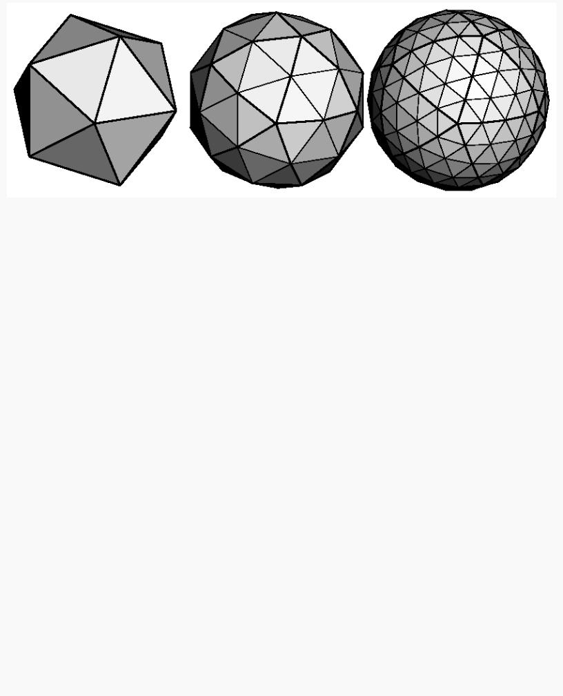
A twenty-sided approximation to a sphere doesn't look good unless the image of the sphere on the screen is quite small, but there's an easy way to increase the accuracy of the approximation. Imagine the icosahedron inscribed in a sphere, and subdivide the triangles as shown in Figure 2-17. The newly introduced vertices lie slightly inside the sphere, so push them to the surface by normalizing them (dividing them by a factor to make them have length 1). This subdivision process can be repeated for arbitrary accuracy. The three objects shown in Figure 2-17 use 20, 80, and 320 approximating triangles, respectively.
http://heron.cc.ukans.edu/ebt-bin/nph-dweb/dynaw...G/@Generic__BookTextView/1963;cs=fullhtml;pt=622 (31 of 34) [4/28/2000 9:44:40 PM]
OpenGL Programming Guide (Addison-Wesley Publishing Company)
Figure 2-17 : Subdividing to Improve a Polygonal Approximation to a Surface
Example 2-16 performs a single subdivision, creating an 80-sided spherical approximation.
Example 2-16 : Single Subdivision
void drawtriangle(float *v1, float *v2, float *v3)
{
glBegin(GL_TRIANGLES); glNormal3fv(v1); vlVertex3fv(v1); glNormal3fv(v2); vlVertex3fv(v2); glNormal3fv(v3); vlVertex3fv(v3);
glEnd();
}
void subdivide(float *v1, float *v2, float *v3)
{
GLfloat v12[3], v23[3], v31[3]; GLint i;
for (i = 0; i < 3; i++) { v12[i] = v1[i]+v2[i]; v23[i] = v2[i]+v3[i]; v31[i] = v3[i]+v1[i];
}
normalize(v12);
normalize(v23);
normalize(v31); drawtriangle(v1, v12, v31); drawtriangle(v2, v23, v12); drawtriangle(v3, v31, v23); drawtriangle(v12, v23, v31);
}
for (i = 0; i < 20; i++) { subdivide(&vdata[tindices[i][0]][0],
&vdata[tindices[i][1]][0],
&vdata[tindices[i][2]][0]);
}
Example 2-17 is a slight modification of Example 2-16 which recursively subdivides the triangles to the proper depth. If the depth value is 0, no subdivisions are performed, and the triangle is drawn as is. If the depth is 1, a single subdivision is performed, and so on.
Example 2-17 : Recursive Subdivision
void subdivide(float *v1, float *v2, float *v3, long depth)
http://heron.cc.ukans.edu/ebt-bin/nph-dweb/dynaw...G/@Generic__BookTextView/1963;cs=fullhtml;pt=622 (32 of 34) [4/28/2000 9:44:40 PM]