

The Official Guide to Learning OpenGL, Version 1.1 (Redbook Second Edition)
.pdfOpenGL Programming Guide (Addison-Wesley Publishing Company)
In addition to the field-of-view considerations, the projection transformation determines how objects are projected onto the screen, as its name suggests. Two basic types of projections are provided for you by OpenGL, along with several corresponding commands for describing the relevant parameters in different ways. One type is the perspective projection, which matches how you see things in daily life. Perspective makes objects that are farther away appear smaller; for example, it makes railroad tracks appear to converge in the distance. If you're trying to make realistic pictures, you'll want to choose perspective projection, which is specified with the glFrustum() command in this code example.
The other type of projection is orthographic, which maps objects directly onto the screen without affecting their relative size. Orthographic projection is used in architectural and computer-aided design applications where the final image needs to reflect the measurements of objects rather than how they might look. Architects create perspective drawings to show how particular buildings or interior spaces look when viewed from various vantage points; the need for orthographic projection arises when blueprint plans or elevations are generated, which are used in the construction of buildings. (See "Projection Transformations" for a discussion of ways to specify both kinds of projection transformations.)
Before glFrustum() can be called to set the projection transformation, some preparation needs to happen. As shown in the reshape() routine in Example 3-1, the command called glMatrixMode() is used first, with the argument GL_PROJECTION. This indicates that the current matrix specifies the projection transformation; the following transformation calls then affect the projection matrix. As you can see, a few lines later glMatrixMode() is called again, this time with GL_MODELVIEW as the argument. This indicates that succeeding transformations now affect the modelview matrix instead of the projection matrix. (See "Manipulating the Matrix Stacks" for more information about how to control the projection and modelview matrices.)
Note that glLoadIdentity() is used to initialize the current projection matrix so that only the specified projection transformation has an effect. Now glFrustum() can be called, with arguments that define the parameters of the projection transformation. In this example, both the projection transformation and the viewport transformation are contained in the reshape() routine, which is called when the window is first created and whenever the window is moved or reshaped. This makes sense, since both projecting (the width to height aspect ratio of the projection viewing volume) and applying the viewport relate directly to the screen, and specifically to the size or aspect ratio of the window on the screen.
Try This
Change the glFrustum() call in Example 3-1 to the more commonly used Utility Library routine gluPerspective() with parameters (60.0, 1.0, 1.5, 20.0). Then experiment with different values, especially for fovy and aspect.
The Viewport Transformation
Together, the projection transformation and the viewport transformation determine how a scene gets mapped onto the computer screen. The projection transformation specifies the mechanics of how the mapping should occur, and the viewport indicates the shape of the available screen area into which the scene is mapped. Since the viewport specifies the region the image occupies on the computer screen, you can think of the viewport transformation as defining the size and location of the final processed
http://heron.cc.ukans.edu/ebt-bin/nph-dweb/dynaw.../@Generic__BookTextView/6635;cs=fullhtml;pt=1963 (9 of 49) [4/28/2000 9:45:03 PM]

OpenGL Programming Guide (Addison-Wesley Publishing Company)
photograph - for example, whether the photograph should be enlarged or shrunk.
The arguments to glViewport() describe the origin of the available screen space within the window - (0, 0) in this example - and the width and height of the available screen area, all measured in pixels on the screen. This is why this command needs to be called within reshape() - if the window changes size, the viewport needs to change accordingly. Note that the width and height are specified using the actual width and height of the window; often, you want to specify the viewport this way rather than giving an absolute size. (See "Viewport Transformation" for more information about how to define the viewport.)
Drawing the Scene
Once all the necessary transformations have been specified, you can draw the scene (that is, take the photograph). As the scene is drawn, OpenGL transforms each vertex of every object in the scene by the modeling and viewing transformations. Each vertex is then transformed as specified by the projection transformation and clipped if it lies outside the viewing volume described by the projection transformation. Finally, the remaining transformed vertices are divided by w and mapped onto the viewport.
General-Purpose Transformation Commands
This section discusses some OpenGL commands that you might find useful as you specify desired transformations. You've already seen a couple of these commands, glMatrixMode() and glLoadIdentity(). The other two commands described here - glLoadMatrix*() and glMultMatrix*() - allow you to specify any transformation matrix directly and then to multiply the current matrix by that specified matrix. More specific transformation commands - such as gluLookAt() and glScale*() - are described in later sections.
As described in the preceding section, you need to state whether you want to modify the modelview or projection matrix before supplying a transformation command. You choose the matrix with glMatrixMode(). When you use nested sets of OpenGL commands that might be called repeatedly, remember to reset the matrix mode correctly. (The glMatrixMode() command can also be used to indicate the texture matrix; texturing is discussed in detail in "The Texture Matrix Stack" in Chapter 9.)
void glMatrixMode(GLenum mode);
Specifies whether the modelview, projection, or texture matrix will be modified, using the argument GL_MODELVIEW, GL_PROJECTION, or GL_TEXTURE for mode. Subsequent transformation commands affect the specified matrix. Note that only one matrix can be modified at a time. By default, the modelview matrix is the one that's modifiable, and all three matrices contain the identity matrix.
You use the glLoadIdentity() command to clear the currently modifiable matrix for future transformation commands, since these commands modify the current matrix. Typically, you always call this command before specifying projection or viewing transformations, but you might also call it before specifying a modeling transformation.
void glLoadIdentity(void);
Sets the currently modifiable matrix to the 4 × 4 identity matrix.
http://heron.cc.ukans.edu/ebt-bin/nph-dweb/dynaw.../@Generic__BookTextView/6635;cs=fullhtml;pt=1963 (10 of 49) [4/28/2000 9:45:03 PM]

OpenGL Programming Guide (Addison-Wesley Publishing Company)
If you want to specify explicitly a particular matrix to be loaded as the current matrix, use glLoadMatrix*(). Similarly, use glMultMatrix*() to multiply the current matrix by the matrix passed in as an argument. The argument for both these commands is a vector of sixteen values (m1, m2, ... , m16) that specifies a matrix M as follows:
Remember that you might be able to maximize efficiency by using display lists to store frequently used matrices (and their inverses) rather than recomputing them. (See "Display-List Design Philosophy" in Chapter 7.) (OpenGL implementations often must compute the inverse of the modelview matrix so that normals and clipping planes can be correctly transformed to eye coordinates.)
Caution: If you're programming in C and you declare a matrix as m[4][4], then the element m[i][j] is in the ith column and jth row of the OpenGL transformation matrix. This is the reverse of the standard C convention in which m[i][j] is in row i and column j. To avoid confusion, you should declare your matrices as m[16].
void glLoadMatrix{fd}(const TYPE *m);
Sets the sixteen values of the current matrix to those specified by m.
void glMultMatrix{fd}(const TYPE *m);
Multiplies the matrix specified by the sixteen values pointed to by m by the current matrix and stores the result as the current matrix.
Note: All matrix multiplication with OpenGL occurs as follows: Suppose the current matrix is C and the matrix specified with glMultMatrix*() or any of the transformation commands is M. After multiplication, the final matrix is always CM. Since matrix multiplication isn't generally commutative, the order makes a difference.
Viewing and Modeling Transformations
Viewing and modeling transformations are inextricably related in OpenGL and are in fact combined into a single modelview matrix. (See "A Simple Example: Drawing a Cube.") One of the toughest problems newcomers to computer graphics face is understanding the effects of combined three-dimensional transformations. As you've already seen, there are alternative ways to think about transformations - do you want to move the camera in one direction, or move the object in the opposite direction? Each way of thinking about transformations has advantages and disadvantages, but in some cases one way more naturally matches the effect of the intended transformation. If you can find a natural approach for your particular application, it's easier to visualize the necessary transformations and then write the corresponding code to specify the matrix manipulations. The first part of this section discusses how to think about transformations; later, specific commands are presented. For now, we use only the matrix-manipulation commands you've already seen. Finally, keep in mind that you must call
http://heron.cc.ukans.edu/ebt-bin/nph-dweb/dynaw.../@Generic__BookTextView/6635;cs=fullhtml;pt=1963 (11 of 49) [4/28/2000 9:45:03 PM]
OpenGL Programming Guide (Addison-Wesley Publishing Company)
glMatrixMode() with GL_MODELVIEW as its argument prior to performing modeling or viewing transformations.
Thinking about Transformations
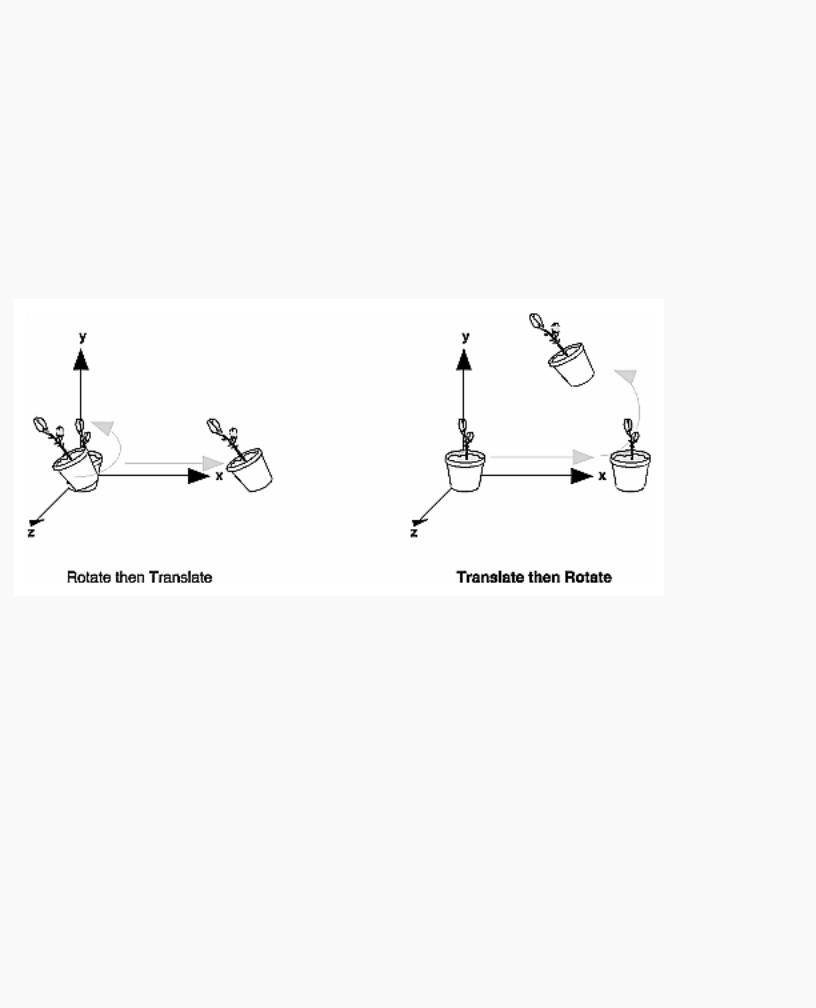
Let's start with a simple case of two transformations: a 45-degree counterclockwise rotation about the origin around the z-axis, and a translation down the x-axis. Suppose that the object you're drawing is small compared to the translation (so that you can see the effect of the translation), and that it's originally located at the origin. If you rotate the object first and then translate it, the rotated object appears on the x-axis. If you translate it down the x-axis first, however, and then rotate about the origin, the object is on the line y=x, as shown in Figure 3-4. In general, the order of transformations is critical. If you do transformation A and then transformation B, you almost always get something different than if you do them in the opposite order.
Figure 3-4 : Rotating First or Translating First
Now let's talk about the order in which you specify a series of transformations. All viewing and modeling transformations are represented as 4 × 4 matrices. Each successive glMultMatrix*() or transformation command multiplies a new 4 × 4 matrix M by the current modelview matrix C to yield CM. Finally, vertices v are multiplied by the current modelview matrix. This process means that the last transformation command called in your program is actually the first one applied to the vertices: CMv. Thus, one way of looking at it is to say that you have to specify the matrices in the reverse order. Like many other things, however, once you've gotten used to thinking about this correctly, backward will seem like forward.
Consider the following code sequence, which draws a single point using three transformations:
glMatrixMode(GL_MODELVIEW); |
|
glLoadIdentity(); |
|
glMultMatrixf(N); |
/* apply transformation N */ |
glMultMatrixf(M); |
/* apply transformation M */ |
http://heron.cc.ukans.edu/ebt-bin/nph-dweb/dynaw.../@Generic__BookTextView/6635;cs=fullhtml;pt=1963 (12 of 49) [4/28/2000 9:45:03 PM]

OpenGL Programming Guide (Addison-Wesley Publishing Company)
glMultMatrixf(L); |
/* apply transformation L */ |
glBegin(GL_POINTS); |
|
glVertex3f(v); |
/* draw transformed vertex v */ |
glEnd(); |
|
With this code, the modelview matrix successively contains I, N, NM, and finally NML, where I represents the identity matrix. The transformed vertex is NMLv. Thus, the vertex transformation is N(M(Lv)) - that is, v is multiplied first by L, the resulting Lv is multiplied by M, and the resulting MLv is multiplied by N. Notice that the transformations to vertex v effectively occur in the opposite order than they were specified. (Actually, only a single multiplication of a vertex by the modelview matrix occurs; in this example, the N, M, and L matrices are already multiplied into a single matrix before it's applied to v.)
Grand, Fixed Coordinate System
Thus, if you like to think in terms of a grand, fixed coordinate system - in which matrix multiplications affect the position, orientation, and scaling of your model - you have to think of the multiplications as occurring in the opposite order from how they appear in the code. Using the simple example shown on the left side of Figure 3-4 (a rotation about the origin and a translation along the x-axis), if you want the object to appear on the axis after the operations, the rotation must occur first, followed by the translation. To do this, you'll need to reverse the order of operations, so the code looks something like this (where R is the rotation matrix and T is the translation matrix):
glMatrixMode(GL_MODELVIEW); |
|
|
glLoadIdentity(); |
|
|
glMultMatrixf(T); |
/* translation |
*/ |
glMultMatrixf(R); |
/* rotation */ |
|
draw_the_object(); |
|
|
Moving a Local Coordinate System
Another way to view matrix multiplications is to forget about a grand, fixed coordinate system in which your model is transformed and instead imagine that a local coordinate system is tied to the object you're drawing. All operations occur relative to this changing coordinate system. With this approach, the matrix multiplications now appear in the natural order in the code. (Regardless of which analogy you're using, the code is the same, but how you think about it differs.) To see this in the translation-rotation example, begin by visualizing the object with a coordinate system tied to it. The translation operation moves the object and its coordinate system down the x-axis. Then, the rotation occurs about the (now-translated) origin, so the object rotates in place in its position on the axis.
This approach is what you should use for applications such as articulated robot arms, where there are joints at the shoulder, elbow, and wrist, and on each of the fingers. To figure out where the tips of the fingers go relative to the body, you'd like to start at the shoulder, go down to the wrist, and so on, applying the appropriate rotations and translations at each joint. Thinking about it in reverse would be far more confusing.
This second approach can be problematic, however, in cases where scaling occurs, and especially so when the scaling is nonuniform (scaling different amounts along the different axes). After uniform
http://heron.cc.ukans.edu/ebt-bin/nph-dweb/dynaw.../@Generic__BookTextView/6635;cs=fullhtml;pt=1963 (13 of 49) [4/28/2000 9:45:03 PM]

OpenGL Programming Guide (Addison-Wesley Publishing Company)
scaling, translations move a vertex by a multiple of what they did before, since the coordinate system is stretched. Nonuniform scaling mixed with rotations may make the axes of the local coordinate system nonperpendicular.
As mentioned earlier, you normally issue viewing transformation commands in your program before any modeling transformations. This way, a vertex in a model is first transformed into the desired orientation and then transformed by the viewing operation. Since the matrix multiplications must be specified in reverse order, the viewing commands need to come first. Note, however, that you don't need to specify either viewing or modeling transformations if you're satisfied with the default conditions. If there's no viewing transformation, the "camera" is left in the default position at the origin, pointed toward the negative z-axis; if there's no modeling transformation, the model isn't moved, and it retains its specified position, orientation, and size.
Since the commands for performing modeling transformations can be used to perform viewing transformations, modeling transformations are discussed first, even if viewing transformations are actually issued first. This order for discussion also matches the way many programmers think when planning their code: Often, they write all the code necessary to compose the scene, which involves transformations to position and orient objects correctly relative to each other. Next, they decide where they want the viewpoint to be relative to the scene they've composed, and then they write the viewing transformations accordingly.
Modeling Transformations
The three OpenGL routines for modeling transformations are glTranslate*(), glRotate*(), and glScale*(). As you might suspect, these routines transform an object (or coordinate system, if you're thinking of it that way) by moving, rotating, stretching, shrinking, or reflecting it. All three commands are equivalent to producing an appropriate translation, rotation, or scaling matrix, and then calling glMultMatrix*() with that matrix as the argument. However, these three routines might be faster than using glMultMatrix*(). OpenGL automatically computes the matrices for you. (See Appendix F if you're interested in the details.)
In the command summaries that follow, each matrix multiplication is described in terms of what it does to the vertices of a geometric object using the fixed coordinate system approach, and in terms of what it does to the local coordinate system that's attached to an object.
Translate
void glTranslate{fd}(TYPEx, TYPE y, TYPEz);
Multiplies the current matrix by a matrix that moves (translates) an object by the given x, y, and z values (or moves the local coordinate system by the same amounts).
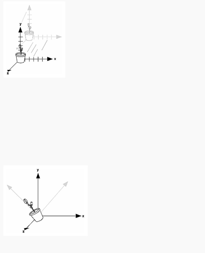
Figure 3-5 shows the effect of glTranslate*().
http://heron.cc.ukans.edu/ebt-bin/nph-dweb/dynaw.../@Generic__BookTextView/6635;cs=fullhtml;pt=1963 (14 of 49) [4/28/2000 9:45:03 PM]
OpenGL Programming Guide (Addison-Wesley Publishing Company)
Figure 3-5 : Translating an Object
Note that using (0.0, 0.0, 0.0) as the argument for glTranslate*() is the identity operation - that is, it has no effect on an object or its local coordinate system.
Rotate
void glRotate{fd}(TYPE angle, TYPE x, TYPE y, TYPE z);
Multiplies the current matrix by a matrix that rotates an object (or the local coordinate system) in a counterclockwise direction about the ray from the origin through the point (x, y, z). The angle parameter specifies the angle of rotation in degrees.
The effect of glRotatef(45.0, 0.0, 0.0, 1.0), which is a rotation of 45 degrees about the z-axis, is shown in Figure 3-6.
Figure 3-6 : Rotating an Object
http://heron.cc.ukans.edu/ebt-bin/nph-dweb/dynaw.../@Generic__BookTextView/6635;cs=fullhtml;pt=1963 (15 of 49) [4/28/2000 9:45:03 PM]
OpenGL Programming Guide (Addison-Wesley Publishing Company)
Note that an object that lies farther from the axis of rotation is more dramatically rotated (has a larger orbit) than an object drawn near the axis. Also, if the angle argument is zero, the glRotate*() command has no effect.
Scale
void glScale{fd}(TYPEx, TYPE y, TYPEz);
Multiplies the current matrix by a matrix that stretches, shrinks, or reflects an object along the axes. Each x, y, and z coordinate of every point in the object is multiplied by the corresponding argument x, y, or z. With the local coordinate system approach, the local coordinate axes are stretched, shrunk, or reflected by the x, y, and z factors, and the associated object is transformed with them.
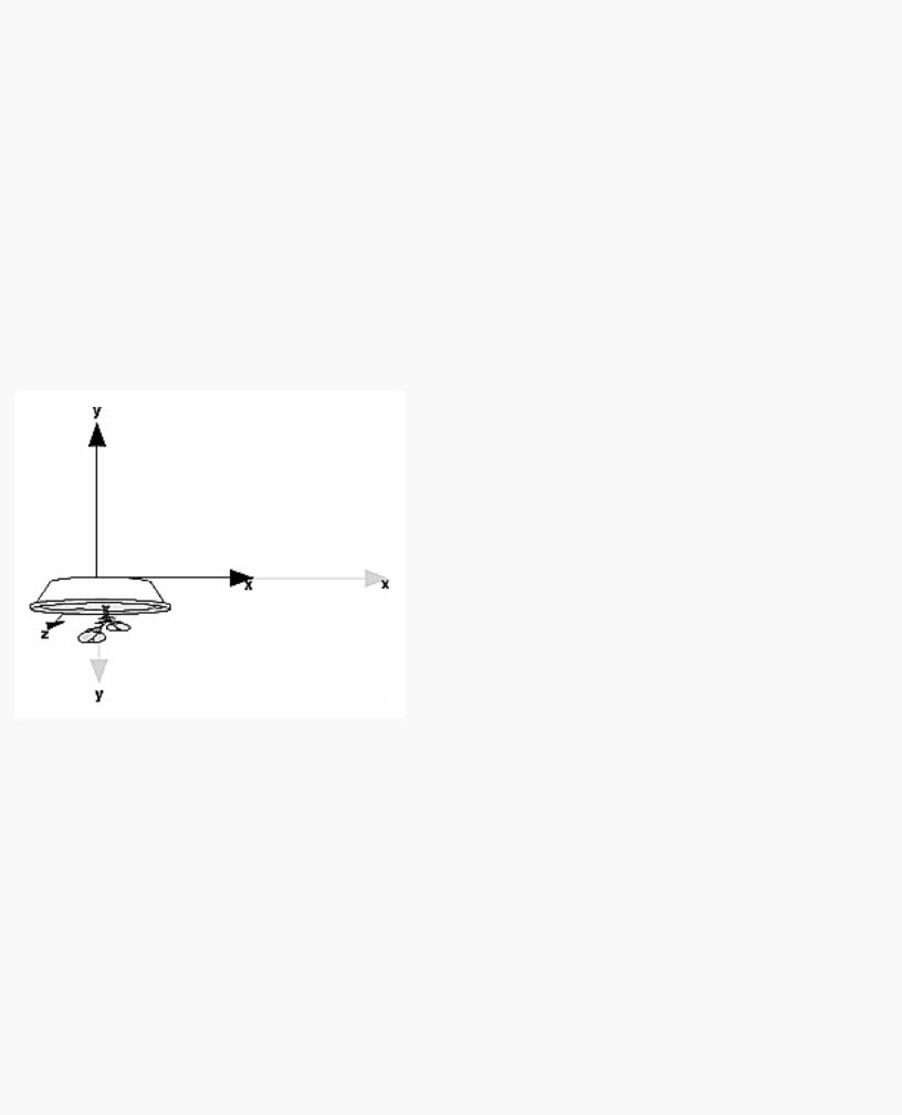
Figure 3-7 shows the effect of glScalef(2.0, -0.5, 1.0).
Figure 3-7 : Scaling and Reflecting an Object
glScale*() is the only one of the three modeling transformations that changes the apparent size of an object: Scaling with values greater than 1.0 stretches an object, and using values less than 1.0 shrinks it. Scaling with a -1.0 value reflects an object across an axis. The identity values for scaling are (1.0, 1.0, 1.0). In general, you should limit your use of glScale*() to those cases where it is necessary. Using glScale*() decreases the performance of lighting calculations, because the normal vectors have to be renormalized after transformation.
Note: A scale value of zero collapses all object coordinates along that axis to zero. It's usually not a good idea to do this, because such an operation cannot be undone. Mathematically speaking, the matrix cannot be inverted, and inverse matrices are required for certain lighting operations. (See Chapter 5.) Sometimes collapsing coordinates does make sense, however; the calculation of shadows on a planar surface is a
http://heron.cc.ukans.edu/ebt-bin/nph-dweb/dynaw.../@Generic__BookTextView/6635;cs=fullhtml;pt=1963 (16 of 49) [4/28/2000 9:45:03 PM]
OpenGL Programming Guide (Addison-Wesley Publishing Company)
typical application. (See "Shadows" in Chapter 14.) In general, if a coordinate system is to be collapsed, the projection matrix should be used rather than the modelview matrix.
A Modeling Transformation Code Example
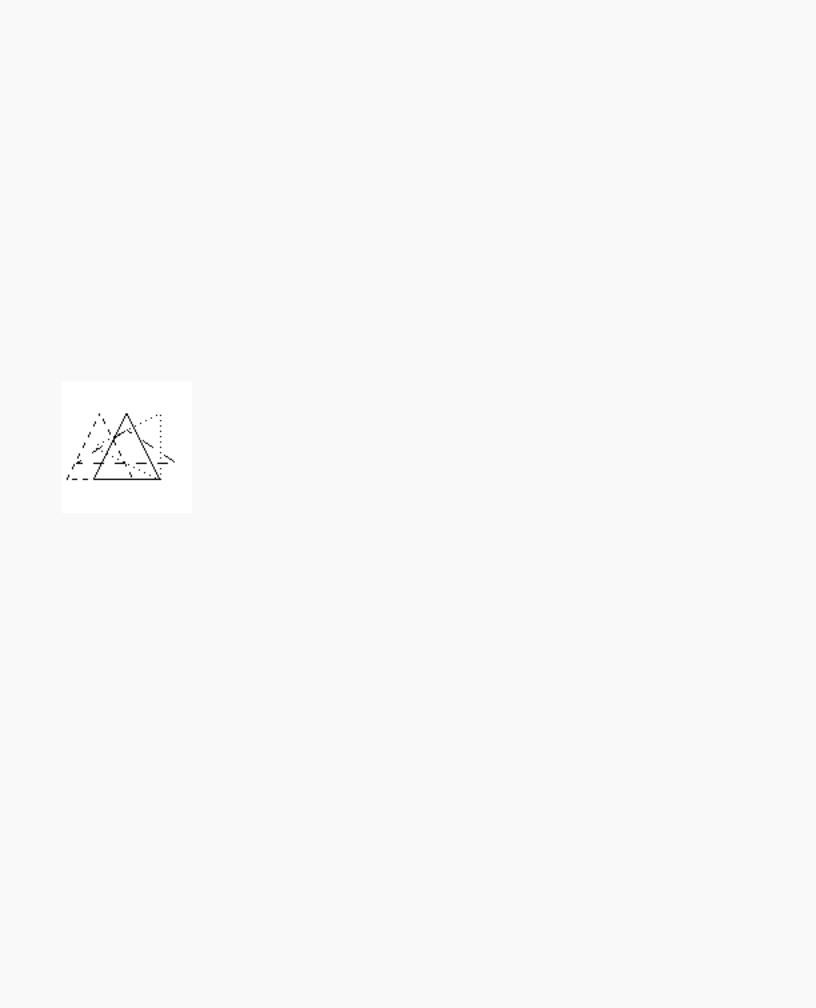
Example 3-2 is a portion of a program that renders a triangle four times, as shown in Figure 3-8. These are the four transformed triangles.
●A solid wireframe triangle is drawn with no modeling transformation.
●The same triangle is drawn again, but with a dashed line stipple and translated (to the left - along the negative x-axis).
●A triangle is drawn with a long dashed line stipple, with its height (y-axis) halved and its width (x-axis) increased by 50%.
●A rotated triangle, made of dotted lines, is drawn.
Figure 3-8 : Modeling Transformation Example
Example 3-2 : Using Modeling Transformations: model.c
glLoadIdentity(); |
|
glColor3f(1.0, 1.0, 1.0); |
|
draw_triangle(); |
/* solid lines */ |
glEnable(GL_LINE_STIPPLE); |
/* dashed lines */ |
glLineStipple(1, 0xF0F0); |
|
glLoadIdentity(); |
|
glTranslatef(-20.0, 0.0, 0.0); |
|
draw_triangle(); |
|
glLineStipple(1, 0xF00F); |
/*long dashed lines */ |
glLoadIdentity(); |
|
glScalef(1.5, 0.5, 1.0); |
|
draw_triangle(); |
|
glLineStipple(1, 0x8888); |
/* dotted lines */ |
http://heron.cc.ukans.edu/ebt-bin/nph-dweb/dynaw.../@Generic__BookTextView/6635;cs=fullhtml;pt=1963 (17 of 49) [4/28/2000 9:45:03 PM]

OpenGL Programming Guide (Addison-Wesley Publishing Company)
glLoadIdentity();
glRotatef (90.0, 0.0, 0.0, 1.0); draw_triangle ();
glDisable (GL_LINE_STIPPLE);
Note the use of glLoadIdentity() to isolate the effects of modeling transformations; initializing the matrix values prevents successive transformations from having a cumulative effect. Even though using glLoadIdentity() repeatedly has the desired effect, it may be inefficient, because you may have to respecify viewing or modeling transformations. (See "Manipulating the Matrix Stacks" for a better way to isolate transformations.)
Note: Sometimes, programmers who want a continuously rotating object attempt to achieve this by repeatedly applying a rotation matrix that has small values. The problem with this technique is that because of round-off errors, the product of thousands of tiny rotations gradually drifts away from the value you really want (it might even become something that isn't a rotation). Instead of using this technique, increment the angle and issue a new rotation command with the new angle at each update step.
Viewing Transformations
A viewing transformation changes the position and orientation of the viewpoint. If you recall the camera analogy, the viewing transformation positions the camera tripod, pointing the camera toward the model. Just as you move the camera to some position and rotate it until it points in the desired direction, viewing transformations are generally composed of translations and rotations. Also remember that to achieve a certain scene composition in the final image or photograph, you can either move the camera or move all the objects in the opposite direction. Thus, a modeling transformation that rotates an object counterclockwise is equivalent to a viewing transformation that rotates the camera clockwise, for example. Finally, keep in mind that the viewing transformation commands must be called before any modeling transformations are performed, so that the modeling transformations take effect on the objects first.
You can manufacture a viewing transformation in any of several ways, as described next. You can also choose to use the default location and orientation of the viewpoint, which is at the origin, looking down the negative z-axis.
●Use one or more modeling transformation commands (that is, glTranslate*() and glRotate*()). You can think of the effect of these transformations as moving the camera position or as moving all the objects in the world, relative to a stationary camera.
●Use the Utility Library routine gluLookAt() to define a line of sight. This routine encapsulates a series of rotation and translation commands.
●Create your own utility routine that encapsulates rotations and translations. Some applications might require custom routines that allow you to specify the viewing transformation in a convenient way. For example, you might want to specify the roll, pitch, and heading rotation angles of a plane in flight, or you might want to specify a transformation in terms of polar coordinates for a camera that's orbiting around an object.
http://heron.cc.ukans.edu/ebt-bin/nph-dweb/dynaw.../@Generic__BookTextView/6635;cs=fullhtml;pt=1963 (18 of 49) [4/28/2000 9:45:03 PM]