

The Official Guide to Learning OpenGL, Version 1.1 (Redbook Second Edition)
.pdfOpenGL Programming Guide (Addison-Wesley Publishing Company)
glutMouseFunc(mouse);
glutMainLoop(); return 0;
}
gluProject() is another Utility Library routine, which is related to gluUnProject().gluProject() mimics the actions of the transformation pipeline. Given three-dimensional world coordinates and all the transformations that affect them, gluProject() returns the transformed window coordinates.
int gluProject(GLdouble objx, GLdouble objy, GLdouble objz, const GLdouble modelMatrix[16], const GLdouble projMatrix[16], const GLint viewport[4], GLdouble *winx, GLdouble *winy, GLdouble *winz);
Map the specified object coordinates (objx, objy, objz) into window coordinates, using transformations defined by a modelview matrix (modelMatrix), projection matrix (projMatrix), and viewport (viewport). The resulting window coordinates are returned in winx, winy, and winz. The function returns GL_TRUE, indicating success, or GL_FALSE, indicating failure.
OpenGL Programming Guide (Addison-Wesley Publishing Company)
http://heron.cc.ukans.edu/ebt-bin/nph-dweb/dynaw.../@Generic__BookTextView/6635;cs=fullhtml;pt=1963 (49 of 49) [4/28/2000 9:45:04 PM]

OpenGL Programming Guide (Addison-Wesley Publishing Company)
OpenGL Programming Guide (Addison-Wesley Publishing Company)
Chapter 4
Color
Chapter Objectives
After reading this chapter, you'll be able to do the following:
●Decide between using RGBA or color-index mode for your application
●Specify desired colors for drawing objects
●Use smooth shading to draw a single polygon with more than one color
The goal of almost all OpenGL applications is to draw color pictures in a window on the screen. The window is a rectangular array of pixels, each of which contains and displays its own color. Thus, in a sense, the point of all the calculations performed by an OpenGL implementation - calculations that take into account OpenGL commands, state information, and values of parameters - is to determine the final color of every pixel that's to be drawn in the window. This chapter explains the commands for specifying colors and how OpenGL interprets them in the following major sections:
●"Color Perception" discusses how the eye perceives color.
●"Computer Color" describes the relationship between pixels on a computer monitor and their colors; it also defines the two display modes, RGBA and color index.
●"RGBA versus Color-Index Mode" explains how the two display modes use graphics hardware and how to decide which mode to use.
●"Specifying a Color and a Shading Model" describes the OpenGL commands you use to specify the desired color or shading model.
Color Perception
Physically, light is composed of photons - tiny particles of light, each traveling along its own path, and each vibrating at its own frequency (or wavelength, or energy - any one of frequency, wavelength, or energy determines the others). A photon is completely characterized by its position, direction, and frequency/wavelength/energy. Photons with wavelengths ranging from about 390 nanometers (nm) (violet) and 720 nm (red) cover the colors of the visible spectrum, forming the colors of a rainbow (violet, indigo, blue, green, yellow, orange, red). However, your eyes perceive lots of colors that aren't in
http://heron.cc.ukans.edu/ebt-bin/nph-dweb/dynaw.../@Generic__BookTextView/9601;cs=fullhtml;pt=6635 (1 of 14) [4/28/2000 9:45:19 PM]

OpenGL Programming Guide (Addison-Wesley Publishing Company)
the rainbow - white, black, brown, and pink, for example. How does this happen?
What your eye actually sees is a mixture of photons of different frequencies. Real light sources are characterized by the distribution of photon frequencies they emit. Ideal white light consists of an equal amount of light of all frequencies. Laser light is usually very pure, and all photons have almost identical frequencies (and direction and phase, as well). Light from a sodium-vapor lamp has more light in the yellow frequency. Light from most stars in space has a distribution that depends heavily on their temperatures (black-body radiation). The frequency distribution of light from most sources in your immediate environment is more complicated.
The human eye perceives color when certain cells in the retina (called cone cells, or just cones) become excited after being struck by photons. The three different kinds of cone cells respond best to three different wavelengths of light: one type of cone cell responds best to red light, one type to green, and the other to blue. (A person who is color-blind is usually missing one or more types of cone cells.) When a given mixture of photons enters the eye, the cone cells in the retina register different degrees of excitation depending on their types, and if a different mixture of photons comes in that happens to excite the three types of cone cells to the same degrees, its color is indistinguishable from that of the first mixture.
Since each color is recorded by the eye as the levels of excitation of the cone cells by the incoming photons, the eye can perceive colors that aren't in the spectrum produced by a prism or rainbow. For example, if you send a mixture of red and blue photons so that both the red and blue cones in the retina are excited, your eye sees it as magenta, which isn't in the spectrum. Other combinations give browns, turquoises, and mauves, none of which appear in the color spectrum.
A computer-graphics monitor emulates visible colors by lighting pixels with a combination of red, green, and blue light in proportions that excite the red-, green-, and blue-sensitive cones in the retina in such a way that it matches the excitation levels generated by the photon mix it's trying to emulate. If humans had more types of cone cells, some that were yellow-sensitive for example, color monitors would probably have a yellow gun as well, and we'd use RGBY (red, green, blue, yellow) quadruples to specify colors. And if everyone were color-blind in the same way, this chapter would be simpler.
To display a particular color, the monitor sends the right amounts of red, green, and blue light to appropriately stimulate the different types of cone cells in your eye. A color monitor can send different proportions of red, green, and blue to each of the pixels, and the eye sees a million or so pinpoints of light, each with its own color.
This section considers only how the eye perceives combinations of photons that enter it. The situation for light bouncing off materials and entering the eye is even more complex - white light bouncing off a red ball will appear red, or yellow light shining through blue glass appears almost black, for example. (See "Real-World and OpenGL Lighting" in Chapter 5 for a discussion of these effects.)
Computer Color
On a color computer screen, the hardware causes each pixel on the screen to emit different amounts of red, green, and blue light. These are called the R, G, and B values. They're often packed together
http://heron.cc.ukans.edu/ebt-bin/nph-dweb/dynaw.../@Generic__BookTextView/9601;cs=fullhtml;pt=6635 (2 of 14) [4/28/2000 9:45:19 PM]

OpenGL Programming Guide (Addison-Wesley Publishing Company)
(sometimes with a fourth value, called alpha, or A), and the packed value is called the RGB (or RGBA) value. (See "Blending" in Chapter 6 for an explanation of the alpha values.) The color information at each pixel can be stored either in RGBA mode, in which the R, G, B, and possibly A values are kept for each pixel, or in color-index mode, in which a single number (called the color index) is stored for each pixel. Each color index indicates an entry in a table that defines a particular set of R, G, and B values. Such a table is called a color map.
In color-index mode, you might want to alter the values in the color map. Since color maps are controlled by the window system, there are no OpenGL commands to do this. All the examples in this book initialize the color-display mode at the time the window is opened by using routines from the GLUT library. (See Appendix D for details.)
There is a great deal of variation among the different graphics hardware platforms in both the size of the pixel array and the number of colors that can be displayed at each pixel. On any graphics system, each pixel has the same amount of memory for storing its color, and all the memory for all the pixels is called the color buffer. The size of a buffer is usually measured in bits, so an 8-bit buffer could store 8 bits of data (256 possible different colors) for each pixel. The size of the possible buffers varies from machine to machine. (See Chapter 10 for more information.)
The R, G, and B values can range from 0.0 (none) to 1.0 (full intensity). For example, R = 0.0, G = 0.0, and B = 1.0 represents the brightest possible blue. If R, G, and B are all 0.0, the pixel is black; if all are 1.0, the pixel is drawn in the brightest white that can be displayed on the screen. Blending green and blue creates shades of cyan. Blue and red combine for magenta. Red and green create yellow. To help you create the colors you want from the R, G, and B components, look at the color cube shown in Plate 12. The axes of this cube represent intensities of red, blue, and green. A black-and-white version of the cube is shown in Figure 4-1.
Figure 4-1 : The Color Cube in Black and White
The commands to specify a color for an object (in this case, a point) can be as simple as this:
http://heron.cc.ukans.edu/ebt-bin/nph-dweb/dynaw.../@Generic__BookTextView/9601;cs=fullhtml;pt=6635 (3 of 14) [4/28/2000 9:45:19 PM]

OpenGL Programming Guide (Addison-Wesley Publishing Company)
glColor3f (1.0, 0.0, 0.0); /* the current RGB color is red: */ /* full red, no green, no blue. */
glBegin (GL_POINTS); glVertex3fv (point_array);
glEnd ();
In certain modes (for example, if lighting or texturing calculations are performed), the assigned color might go through other operations before arriving in the framebuffer as a value representing a color for a pixel. In fact, the color of a pixel is determined by a lengthy sequence of operations.
Early in a program's execution, the color-display mode is set to either RGBA mode or color-index mode. Once the color-display mode is initialized, it can't be changed. As the program executes, a color (either a color index or an RGBA value) is determined on a per-vertex basis for each geometric primitive. This color is either a color you've explicitly specified for a vertex or, if lighting is enabled, is determined from the interaction of the transformation matrices with the surface normals and other material properties. In other words, a red ball with a blue light shining on it looks different from the same ball with no light on it. (See Chapter 5 for details.) After the relevant lighting calculations are performed, the chosen shading model is applied. As explained in "Specifying a Color and a Shading Model," you can choose flat or smooth shading, each of which has different effects on the eventual color of a pixel.
Next, the primitives are rasterized, or converted to a two-dimensional image. Rasterizing involves determining which squares of an integer grid in window coordinates are occupied by the primitive and then assigning color and other values to each such square. A grid square along with its associated values of color, z (depth), and texture coordinates is called a fragment. Pixels are elements of the framebuffer; a fragment comes from a primitive and is combined with its corresponding pixel to yield a new pixel. Once a fragment is constructed, texturing, fog, and antialiasing are applied - if they're enabled - to the fragments. After that, any specified alpha blending, dithering, and bitwise logical operations are carried out using the fragment and the pixel already stored in the framebuffer. Finally, the fragment's color value (either color index or RGBA) is written into the pixel and displayed in the window using the window's color-display mode.
RGBA versus Color-Index Mode
In either color-index or RGBA mode, a certain amount of color data is stored at each pixel. This amount is determined by the number of bitplanes in the framebuffer. A bitplane contains 1 bit of data for each pixel. If there are 8color bitplanes, there are 8 color bits per pixel, and hence 28 = 256 different values or colors that can be stored at the pixel.
Bitplanes are often divided evenly into storage for R, G, and B components (that is, a 24-bitplane system devotes 8 bits each to red, green, and blue), but this isn't always true. To find out the number of bitplanes available on your system for red, green, blue, alpha, or color-index values, use glGetIntegerv() with GL_RED_BITS, GL_GREEN_BITS, GL_BLUE_BITS, GL_ALPHA_BITS, and GL_INDEX_BITS.
Note: Color intensities on most computer screens aren't perceived as linear by the human eye. Consider colors consisting of just a red component, with green and blue set to zero. As the intensity varies from 0.0 (off) to 1.0 (full on), the number of electrons striking the pixels increases, but the question is, does
http://heron.cc.ukans.edu/ebt-bin/nph-dweb/dynaw.../@Generic__BookTextView/9601;cs=fullhtml;pt=6635 (4 of 14) [4/28/2000 9:45:19 PM]
OpenGL Programming Guide (Addison-Wesley Publishing Company)
0.5 look like halfway between 0.0 and 1.0? To test this, write a program that draws alternate pixels in a checkerboard pattern to intensities 0.0 and 1.0, and compare it with a region drawn solidly in color 0.5. From a reasonable distance from the screen, the two regions should appear to have the same intensity. If they look noticeably different, you need to use whatever correction mechanism is provided on your particular system. For example, many systems have a table to adjust intensities so that 0.5 appears to be halfway between 0.0 and 1.0. The mapping generally used is an exponential one, with the exponent referred to as gamma (hence the term gamma correction). Using the same gamma for the red, green, and blue components gives pretty good results, but three different gamma values might give slightly better results. (For more details on this topic, see Foley, van Dam, et al. Computer Graphics: Principles and Practice. Reading, MA: Addison-Wesley Developers Press, 1990.)
RGBA Display Mode
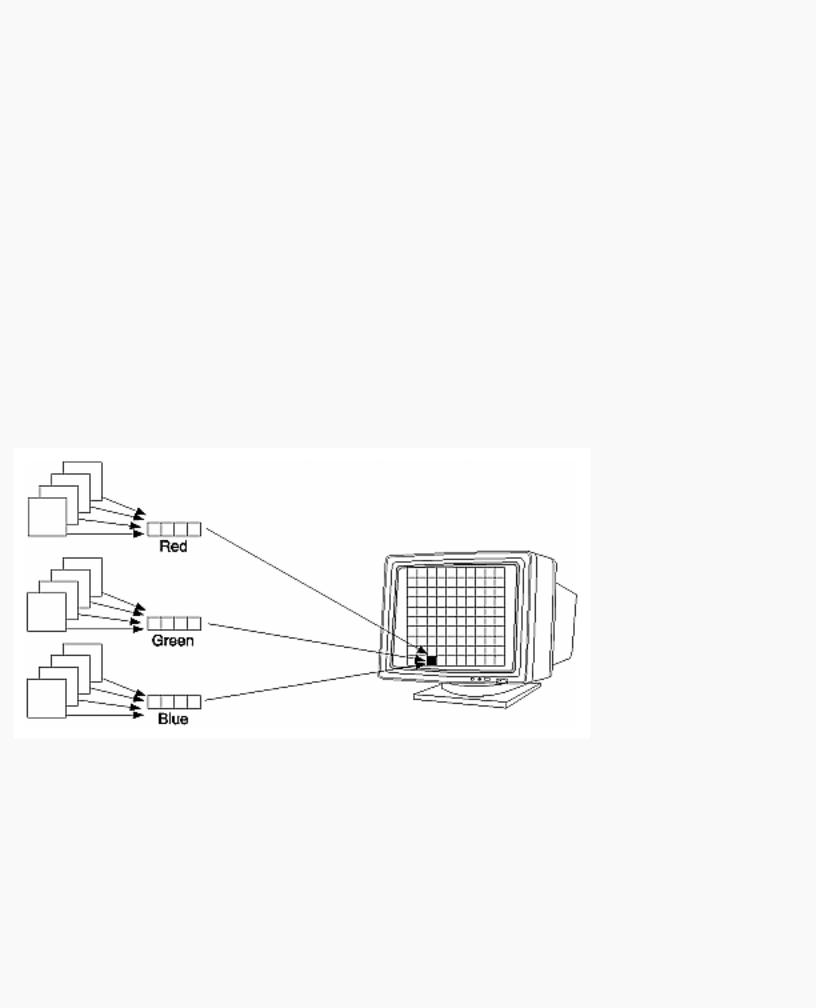
In RGBA mode, the hardware sets aside a certain number of bitplanes for each of the R, G, B, and A components (not necessarily the same number for each component) as shown in Figure 4-2. The R, G, and B values are typically stored as integers rather than floating-point numbers, and they're scaled to the number of available bits for storage and retrieval. For example, if a system has 8 bits available for the R component, integers between 0 and 255 can be stored; thus, 0, 1, 2, ..., 255 in the bitplanes would correspond to R values of 0/255 = 0.0, 1/255, 2/255, ..., 255/255 = 1.0. Regardless of the number of bitplanes, 0.0 specifies the minimum intensity, and 1.0 specifies the maximum intensity.
Figure 4-2 : RGB Values from the Bitplanes
Note: The alpha value (the A in RGBA) has no direct effect on the color displayed on the screen. It can be used for many things, including blending and transparency, and it can have an effect on the values of R, G, and B that are written. (See "Blending" in Chapter 6 for more information about alpha values.)
The number of distinct colors that can be displayed at a single pixel depends on the number of bitplanes and the capacity of the hardware to interpret those bitplanes. The number of distinct colors can't exceed 2n, where n is the number of bitplanes. Thus, a machine with 24 bitplanes for RGB can display up to
http://heron.cc.ukans.edu/ebt-bin/nph-dweb/dynaw.../@Generic__BookTextView/9601;cs=fullhtml;pt=6635 (5 of 14) [4/28/2000 9:45:19 PM]

OpenGL Programming Guide (Addison-Wesley Publishing Company)
16.77 million distinct colors.
Dithering
Advanced
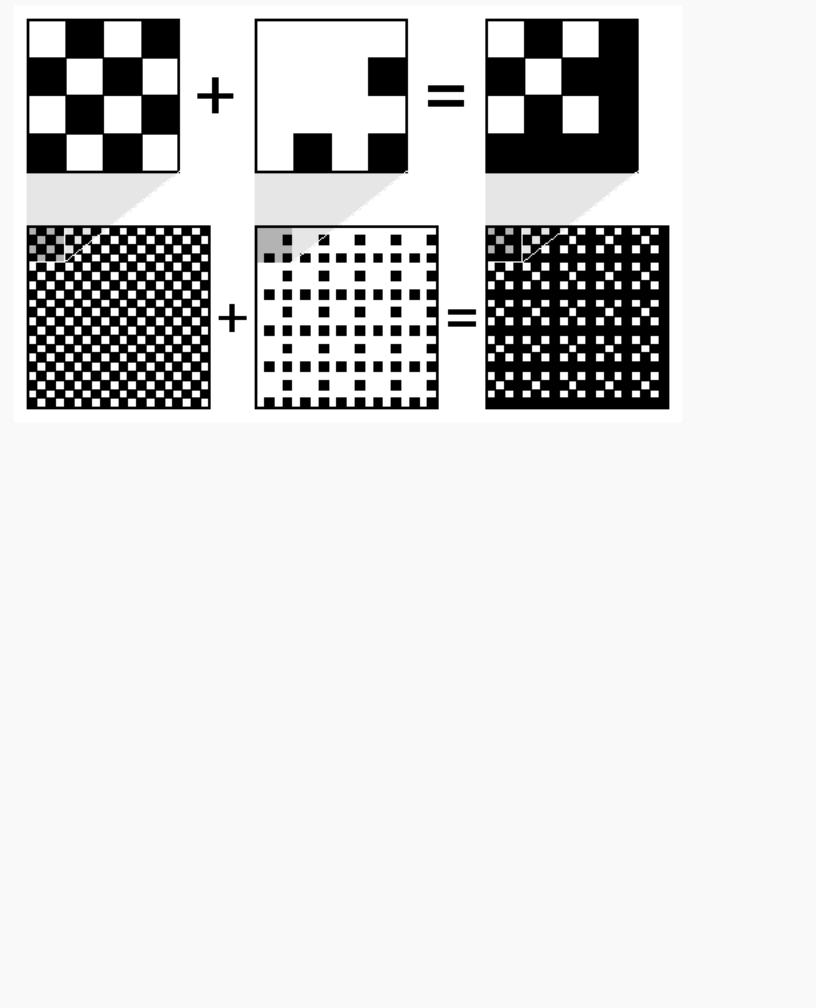
Some graphics hardware uses dithering to increase the number of apparent colors. Dithering is the technique of using combinations of some colors to create the effect of other colors. To illustrate how dithering works, suppose your system has only 1 bit each for R, G, and B and thus can display only eight colors: black, white, red, blue, green, yellow, cyan, and magenta. To display a pink region, the hardware can fill the region in a checkerboard manner, alternating red and white pixels. If your eye is far enough away from the screen that it can't distinguish individual pixels, the region appears pink - the average of red and white. Redder pinks can be achieved by filling a higher proportion of the pixels with red, whiter pinks would use more white pixels, and so on.
With this technique, there are no pink pixels. The only way to achieve the effect of "pinkness" is to cover a region consisting of multiple pixels - you can't dither a single pixel. If you specify an RGB value for an unavailable color and fill a polygon, the hardware fills the pixels in the interior of the polygon with a mixture of nearby colors whose average appears to your eye to be the color you want. (Remember, though, that if you're reading pixel information out of the framebuffer, you get the actual red and white pixel values, since there aren't any pink ones. See Chapter 8 for more information about reading pixel values.)
Figure 4-3 illustrates some simple dithering of black and white pixels to make shades of gray. From left to right, the 4 × 4 patterns at the top represent dithering patterns for 50 percent, 19 percent, and 69 percent gray. Under each pattern, you can see repeated reduced copies of each pattern, but these black and white squares are still bigger than most pixels. If you look at them from across the room, you can see that they blur together and appear as three levels of gray.
http://heron.cc.ukans.edu/ebt-bin/nph-dweb/dynaw.../@Generic__BookTextView/9601;cs=fullhtml;pt=6635 (6 of 14) [4/28/2000 9:45:19 PM]
OpenGL Programming Guide (Addison-Wesley Publishing Company)
Figure 4-3 : Dithering Black and White to Create Gray
With about 8 bits each of R, G, and B, you can get a fairly high-quality image without dithering. Just because your machine has 24 color bitplanes, however, doesn't mean that dithering won't be desirable. For example, if you are running in double-buffer mode, the bitplanes might be divided into two sets of twelve, so there are really only 4 bits each per R, G, and B component. Without dithering, 4-bit-per-component color can give less than satisfactory results in many situations.
You enable or disable dithering by passing GL_DITHER to glEnable() or glDisable(). Note that dithering, unlike many other features, is enabled by default.
Color-Index Display Mode
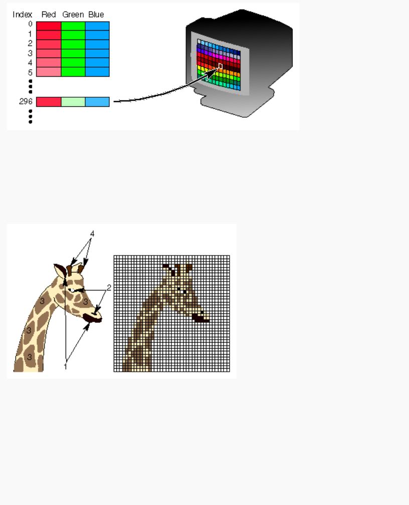
With color-index mode, OpenGL uses a color map (or lookup table), which is similar to using a palette to mix paints to prepare for a paint-by-number scene. A painter's palette provides spaces to mix paints together; similarly, a computer's color map provides indices where the primary red, green, and blue values can be mixed, as shown in Figure 4-4.
http://heron.cc.ukans.edu/ebt-bin/nph-dweb/dynaw.../@Generic__BookTextView/9601;cs=fullhtml;pt=6635 (7 of 14) [4/28/2000 9:45:19 PM]
OpenGL Programming Guide (Addison-Wesley Publishing Company)
Figure 4-4 : A Color Map
A painter filling in a paint-by-number scene chooses a color from the color palette and fills the corresponding numbered regions with that color. A computer stores the color index in the bitplanes for each pixel. Then those bitplane values reference the color map, and the screen is painted with the corresponding red, green, and blue values from the color map, as shown in Figure 4-5.
Figure 4-5 : Using a Color Map to Paint a Picture
In color-index mode, the number of simultaneously available colors is limited by the size of the color map and the number of bitplanes available. The size of the color map is determined by the amount of hardware dedicated to it. The size of the color map is always a power of 2, and typical sizes range from 256 (28) to 4096 (212), where the exponent is the number of bitplanes being used. If there are 2n indices in the color map and m available bitplanes, the number of usable entries is the smaller of 2n and 2m.
With RGBA mode, each pixel's color is independent of other pixels. However, in color-index mode, each
http://heron.cc.ukans.edu/ebt-bin/nph-dweb/dynaw.../@Generic__BookTextView/9601;cs=fullhtml;pt=6635 (8 of 14) [4/28/2000 9:45:19 PM]

OpenGL Programming Guide (Addison-Wesley Publishing Company)
pixel with the same index stored in its bitplanes shares the same color-map location. If the contents of an entry in the color map change, then all pixels of that color index change their color.
Choosing between RGBA and Color-Index Mode
You should base your decision to use RGBA or color-index mode on what hardware is available and on what your application needs. For most systems, more colors can be simultaneously represented with RGBA mode than with color-index mode. Also, for several effects, such as shading, lighting, texture mapping, and fog, RGBA provides more flexibility than color-index mode.
You might prefer to use color-index mode in the following cases:
●If you're porting an existing application that makes significant use of color-index mode, it might be easier to not change to RGBA mode.
●If you have a small number of bitplanes available, RGBA mode may produce noticeably coarse shades of colors. For example, if you have only 8 bitplanes, in RGBA mode, you may have only 3 bits for red, 3 bits for green, and 2 bits for blue. You'd only have 8 (23) shades of red and green, and only 4 shades of blue. The gradients between color shades are likely to be very obvious.
In this situation, if you have limited shading requirements, you can use the color lookup table to load more shades of colors. For example, if you need only shades of blue, you can use color-index mode and store up to 256 (28) shades of blue in the color-lookup table, which is much better than the 4 shades you would have in RGBA mode. Of course, this example would use up your entire color-lookup table, so you would have no shades of red, green, or other combined colors.
●Color-index mode can be useful for various tricks, such as color-map animation and drawing in layers. (See Chapter 14 for more information.)
In general, use RGBA mode wherever possible. It works with texture mapping and works better with lighting, shading, fog, antialiasing, and blending.
Changing between Display Modes
In the best of all possible worlds, you might want to avoid making a choice between RGBA and color-index display mode. For example, you may want to use color-index mode for a color-map animation effect and then, when needed, immediately change the scene to RGBA mode for texture mapping.
Or similarly, you may desire to switch between single and double buffering. For example, you may have very few bitplanes; let's say 8 bitplanes. In single-buffer mode, you'll have 256 (28) colors, but if you are using double-buffer mode to eliminate flickering from your animated program, you may only have 16 (24) colors. Perhaps you want to draw a moving object without flicker and are willing to sacrifice colors for using double-buffer mode (maybe the object is moving so fast that the viewer won't notice the details). But when the object comes to rest, you will want to draw it in single-buffer mode so that you can use more colors.
Unfortunately, most window systems won't allow an easy switch. For example, with the X Window
http://heron.cc.ukans.edu/ebt-bin/nph-dweb/dynaw.../@Generic__BookTextView/9601;cs=fullhtml;pt=6635 (9 of 14) [4/28/2000 9:45:19 PM]