

The Official Guide to Learning OpenGL, Version 1.1 (Redbook Second Edition)
.pdfOpenGL Programming Guide (Addison-Wesley Publishing Company)
{
GLfloat v12[3], v23[3], v31[3]; GLint i;
if (depth == 0) { drawtriangle(v1, v2, v3); return;
}
for (i = 0; i < 3; i++) { v12[i] = v1[i]+v2[i]; v23[i] = v2[i]+v3[i]; v31[i] = v3[i]+v1[i];
}
normalize(v12);
normalize(v23);
normalize(v31);
subdivide(v1, v12, v31, depth-1); subdivide(v2, v23, v12, depth-1); subdivide(v3, v31, v23, depth-1); subdivide(v12, v23, v31, depth-1);
}
Generalized Subdivision
A recursive subdivision technique such as the one described in Example 2-17 can be used for other types of surfaces. Typically, the recursion ends either if a certain depth is reached or if some condition on the curvature is satisfied (highly curved parts of surfaces look better with more subdivision).
To look at a more general solution to the problem of subdivision, consider an arbitrary surface parameterized by two variables u[0] and u[1]. Suppose that two routines are provided:
void surf(GLfloat u[2], GLfloat vertex[3], GLfloat normal[3]); float curv(GLfloat u[2]);
If surf() is passed u[], the corresponding three-dimensional vertex and normal vectors (of length 1) are returned. If u[] is passed to curv(), the curvature of the surface at that point is calculated and returned. (See an introductory textbook on differential geometry for more information about measuring surface curvature.)
Example 2-18 shows the recursive routine that subdivides a triangle either until the maximum depth is reached or until the maximum curvature at the three vertices is less than some cutoff.
Example 2-18 : Generalized Subdivision
void subdivide(float u1[2], float u2[2], float u3[2], float cutoff, long depth)
{
GLfloat v1[3], v2[3], v3[3], n1[3], n2[3], n3[3]; GLfloat u12[2], u23[2], u32[2];
GLint i;
if (depth == maxdepth || (curv(u1) < cutoff && curv(u2) < cutoff && curv(u3) < cutoff)) {
surf(u1, v1, n1); surf(u2, v2, n2); surf(u3, v3, n3); glBegin(GL_POLYGON);
glNormal3fv(n1); glVertex3fv(v1); glNormal3fv(n2); glVertex3fv(v2); glNormal3fv(n3); glVertex3fv(v3);
glEnd();
return;
}
for (i = 0; i < 2; i++) { u12[i] = (u1[i] + u2[i])/2.0; u23[i] = (u2[i] + u3[i])/2.0; u31[i] = (u3[i] + u1[i])/2.0;
}
subdivide(u1, u12, u31, cutoff, depth+1); subdivide(u2, u23, u12, cutoff, depth+1);
http://heron.cc.ukans.edu/ebt-bin/nph-dweb/dynaw...G/@Generic__BookTextView/1963;cs=fullhtml;pt=622 (33 of 34) [4/28/2000 9:44:40 PM]

OpenGL Programming Guide (Addison-Wesley Publishing Company)
subdivide(u3, u31, u23, cutoff, depth+1); subdivide(u12, u23, u31, cutoff, depth+1);
}
OpenGL Programming Guide (Addison-Wesley Publishing Company)
http://heron.cc.ukans.edu/ebt-bin/nph-dweb/dynaw...G/@Generic__BookTextView/1963;cs=fullhtml;pt=622 (34 of 34) [4/28/2000 9:44:40 PM]

OpenGL Programming Guide (Addison-Wesley Publishing Company)
OpenGL Programming Guide (Addison-Wesley Publishing Company)
Chapter 3
Viewing
Chapter Objectives
After reading this chapter, you'll be able to do the following:
●View a geometric model in any orientation by transforming it in three-dimensional space
●Control the location in three-dimensional space from which the model is viewed
●Clip undesired portions of the model out of the scene that's to be viewed
●Manipulate the appropriate matrix stacks that control model transformation for viewing and project the model onto the screen
●Combine multiple transformations to mimic sophisticated systems in motion, such as a solar system or an articulated robot arm
●Reverse or mimic the operations of the geometric processing pipeline
Chapter 2 explained how to instruct OpenGL to draw the geometric models you want displayed in your scene. Now you must decide how you want to position the models in the scene, and you must choose a vantage point from which to view the scene. You can use the default positioning and vantage point, but most likely you want to specify them.
Look at the image on the cover of this book. The program that produced that image contained a single geometric description of a building block. Each block was carefully positioned in the scene: Some blocks were scattered on the floor, some were stacked on top of each other on the table, and some were assembled to make the globe. Also, a particular viewpoint had to be chosen. Obviously, we wanted to look at the corner of the room containing the globe. But how far away from the scene - and where exactly - should the viewer be? We wanted to make sure that the final image of the scene contained a good view out the window, that a portion of the floor was visible, and that all the objects in the scene were not only visible but presented in an interesting arrangement. This chapter explains how to use OpenGL to accomplish these tasks: how to position and orient models in three-dimensional space and how to establish the location - also in three-dimensional space - of the viewpoint. All of these factors help determine exactly what image appears on the screen.
You want to remember that the point of computer graphics is to create a two-dimensional image of three-dimensional objects (it has to be two-dimensional because it's drawn on a flat screen), but you need to think in three-dimensional coordinates while making many of the decisions that determine what gets
http://heron.cc.ukans.edu/ebt-bin/nph-dweb/dynaw.../@Generic__BookTextView/6635;cs=fullhtml;pt=1963 (1 of 49) [4/28/2000 9:45:03 PM]

OpenGL Programming Guide (Addison-Wesley Publishing Company)
drawn on the screen. A common mistake people make when creating three-dimensional graphics is to start thinking too soon that the final image appears on a flat, two-dimensional screen. Avoid thinking about which pixels need to be drawn, and instead try to visualize three-dimensional space. Create your models in some three-dimensional universe that lies deep inside your computer, and let the computer do its job of calculating which pixels to color.
A series of three computer operations convert an object's three-dimensional coordinates to pixel positions on the screen.
●Transformations, which are represented by matrix multiplication, include modeling, viewing, and projection operations. Such operations include rotation, translation, scaling, reflecting, orthographic projection, and perspective projection. Generally, you use a combination of several transformations to draw a scene.
●Since the scene is rendered on a rectangular window, objects (or parts of objects) that lie outside the window must be clipped. In three-dimensional computer graphics, clipping occurs by throwing out objects on one side of a clipping plane.
●Finally, a correspondence must be established between the transformed coordinates and screen pixels. This is known as a viewport transformation.
This chapter describes all of these operations, and how to control them, in the following major sections:
●"Overview: The Camera Analogy" gives an overview of the transformation process by describing the analogy of taking a photograph with a camera, presents a simple example program that transforms an object, and briefly describes the basic OpenGL transformation commands.
●"Viewing and Modeling Transformations" explains in detail how to specify and to imagine the effect of viewing and modeling transformations. These transformations orient the model and the camera relative to each other to obtain the desired final image.
●"Projection Transformations" describes how to specify the shape and orientation of the viewing volume. The viewing volume determines how a scene is projected onto the screen (with a perspective or orthographic projection) and which objects or parts of objects are clipped out of the scene.
●"Viewport Transformation" explains how to control the conversion of three-dimensional model coordinates to screen coordinates.
●"Troubleshooting Transformations" presents some tips for discovering why you might not be getting the desired effect from your modeling, viewing, projection, and viewport transformations.
●"Manipulating the Matrix Stacks" discusses how to save and restore certain transformations. This is particularly useful when you're drawing complicated objects that are built up from simpler ones.
http://heron.cc.ukans.edu/ebt-bin/nph-dweb/dynaw.../@Generic__BookTextView/6635;cs=fullhtml;pt=1963 (2 of 49) [4/28/2000 9:45:03 PM]

OpenGL Programming Guide (Addison-Wesley Publishing Company)
●"Additional Clipping Planes" describes how to specify additional clipping planes beyond those defined by the viewing volume.
●"Examples of Composing Several Transformations" walks you through a couple of more complicated uses for transformations.
●"Reversing or Mimicking Transformations" shows you how to take a transformed point in window coordinates and reverse the transformation to obtain its original object coordinates. The transformation itself (without reversal) can also be emulated.
Overview: The Camera Analogy
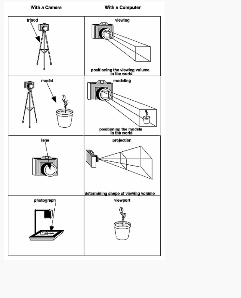
The transformation process to produce the desired scene for viewing is analogous to taking a photograph with a camera. As shown in Figure 3-1, the steps with a camera (or a computer) might be the following.
1.Set up your tripod and pointing the camera at the scene (viewing transformation).
2.Arrange the scene to be photographed into the desired composition (modeling transformation).
3.Choose a camera lens or adjust the zoom (projection transformation).
4.Determine how large you want the final photograph to be - for example, you might want it enlarged (viewport transformation).
After these steps are performed, the picture can be snapped or the scene can be drawn.
http://heron.cc.ukans.edu/ebt-bin/nph-dweb/dynaw.../@Generic__BookTextView/6635;cs=fullhtml;pt=1963 (3 of 49) [4/28/2000 9:45:03 PM]
OpenGL Programming Guide (Addison-Wesley Publishing Company)
Figure 3-1 : The Camera Analogy
Note that these steps correspond to the order in which you specify the desired transformations in your
http://heron.cc.ukans.edu/ebt-bin/nph-dweb/dynaw.../@Generic__BookTextView/6635;cs=fullhtml;pt=1963 (4 of 49) [4/28/2000 9:45:03 PM]

OpenGL Programming Guide (Addison-Wesley Publishing Company)
program, not necessarily the order in which the relevant mathematical operations are performed on an object's vertices. The viewing transformations must precede the modeling transformations in your code, but you can specify the projection and viewport transformations at any point before drawing occurs. Figure 3-2 shows the order in which these operations occur on your computer.
Figure 3-2 : Stages of Vertex Transformation
To specify viewing, modeling, and projection transformations, you construct a 4 × 4 matrix M, which is then multiplied by the coordinates of each vertex v in the scene to accomplish the transformation
v'=Mv
(Remember that vertices always have four coordinates (x, y, z, w), though in most cases w is 1 and for two-dimensional data z is 0.) Note that viewing and modeling transformations are automatically applied to surface normal vectors, in addition to vertices. (Normal vectors are used only in eye coordinates.) This ensures that the normal vector's relationship to the vertex data is properly preserved.
The viewing and modeling transformations you specify are combined to form the modelview matrix, which is applied to the incoming object coordinates to yield eye coordinates. Next, if you've specified additional clipping planes to remove certain objects from the scene or to provide cutaway views of objects, these clipping planes are applied.
After that, OpenGL applies the projection matrix to yield clip coordinates. This transformation defines a viewing volume; objects outside this volume are clipped so that they're not drawn in the final scene. After this point, the perspective division is performed by dividing coordinate values by w, to produce normalized device coordinates. (See Appendix F for more information about the meaning of the w coordinate and how it affects matrix transformations.) Finally, the transformed coordinates are converted to window coordinates by applying the viewport transformation. You can manipulate the dimensions of the viewport to cause the final image to be enlarged, shrunk, or stretched.
You might correctly suppose that the x and y coordinates are sufficient to determine which pixels need to be drawn on the screen. However, all the transformations are performed on the z coordinates as well. This way, at the end of this transformation process, the z values correctly reflect the depth of a given
http://heron.cc.ukans.edu/ebt-bin/nph-dweb/dynaw.../@Generic__BookTextView/6635;cs=fullhtml;pt=1963 (5 of 49) [4/28/2000 9:45:03 PM]
OpenGL Programming Guide (Addison-Wesley Publishing Company)
vertex (measured in distance away from the screen). One use for this depth value is to eliminate unnecessary drawing. For example, suppose two vertices have the same x and y values but different z values. OpenGL can use this information to determine which surfaces are obscured by other surfaces and can then avoid drawing the hidden surfaces. (See Chapter 10 for more information about this technique, which is called hidden-surface removal.)
As you've probably guessed by now, you need to know a few things about matrix mathematics to get the most out of this chapter. If you want to brush up on your knowledge in this area, you might consult a textbook on linear algebra.
A Simple Example: Drawing a Cube
Example 3-1 draws a cube that's scaled by a modeling transformation (see Figure 3-3). The viewing transformation, gluLookAt(), positions and aims the camera towards where the cube is drawn. A projection transformation and a viewport transformation are also specified. The rest of this section walks you through Example 3-1 and briefly explains the transformation commands it uses. The succeeding sections contain the complete, detailed discussion of all OpenGL's transformation commands.
Figure 3-3 : Transformed Cube
Example 3-1 : Transformed Cube: cube.c
#include <GL/gl.h> #include <GL/glu.h> #include <GL/glut.h>
void init(void)
{
glClearColor (0.0, 0.0, 0.0, 0.0); glShadeModel (GL_FLAT);
}
void display(void) |
|
{ |
|
glClear (GL_COLOR_BUFFER_BIT); |
|
glColor3f (1.0, 1.0, 1.0); |
|
glLoadIdentity (); |
/* clear the matrix */ |
/* viewing transformation */
http://heron.cc.ukans.edu/ebt-bin/nph-dweb/dynaw.../@Generic__BookTextView/6635;cs=fullhtml;pt=1963 (6 of 49) [4/28/2000 9:45:03 PM]

OpenGL Programming Guide (Addison-Wesley Publishing Company)
gluLookAt (0.0, 0.0, 5.0, 0.0, 0.0, 0.0, 0.0, 1.0, 0.0); glScalef (1.0, 2.0, 1.0); /* modeling transformation */ glutWireCube (1.0);
glFlush ();
}
void reshape (int w, int h)
{
glViewport (0, 0, (GLsizei) w, (GLsizei) h); glMatrixMode (GL_PROJECTION); glLoadIdentity ();
glFrustum (-1.0, 1.0, -1.0, 1.0, 1.5, 20.0); glMatrixMode (GL_MODELVIEW);
}
int main(int argc, char** argv)
{
glutInit(&argc, argv);
glutInitDisplayMode (GLUT_SINGLE | GLUT_RGB); glutInitWindowSize (500, 500); glutInitWindowPosition (100, 100); glutCreateWindow (argv[0]);
init (); glutDisplayFunc(display); glutReshapeFunc(reshape); glutMainLoop();
return 0;
}
The Viewing Transformation
Recall that the viewing transformation is analogous to positioning and aiming a camera. In this code example, before the viewing transformation can be specified, the current matrix is set to the identity matrix with glLoadIdentity(). This step is necessary since most of the transformation commands multiply the current matrix by the specified matrix and then set the result to be the current matrix. If you don't clear the current matrix by loading it with the identity matrix, you continue to combine previous transformation matrices with the new one you supply. In some cases, you do want to perform such combinations, but you also need to clear the matrix sometimes.
In Example 3-1, after the matrix is initialized, the viewing transformation is specified with gluLookAt(). The arguments for this command indicate where the camera (or eye position) is placed, where it is aimed, and which way is up. The arguments used here place the camera at (0, 0, 5), aim the camera lens towards (0, 0, 0), and specify the up-vector as (0, 1, 0). The up-vector defines a unique orientation for the camera.
If gluLookAt() was not called, the camera has a default position and orientation. By default, the camera is situated at the origin, points down the negative z-axis, and has an up-vector of (0, 1, 0). So in Example
http://heron.cc.ukans.edu/ebt-bin/nph-dweb/dynaw.../@Generic__BookTextView/6635;cs=fullhtml;pt=1963 (7 of 49) [4/28/2000 9:45:03 PM]

OpenGL Programming Guide (Addison-Wesley Publishing Company)
3-1, the overall effect is that gluLookAt() moves the camera 5 units along the z-axis. (See "Viewing and Modeling Transformations" for more information about viewing transformations.)
The Modeling Transformation
You use the modeling transformation to position and orient the model. For example, you can rotate, translate, or scale the model - or perform some combination of these operations. In Example 3-1, glScalef() is the modeling transformation that is used. The arguments for this command specify how scaling should occur along the three axes. If all the arguments are 1.0, this command has no effect. In Example 3-1, the cube is drawn twice as large in the y direction. Thus, if one corner of the cube had originally been at (3.0, 3.0, 3.0), that corner would wind up being drawn at (3.0, 6.0, 3.0). The effect of this modeling transformation is to transform the cube so that it isn't a cube but a rectangular box.
Try This
Change the gluLookAt() call in Example 3-1 to the modeling transformation glTranslatef() with parameters (0.0, 0.0, -5.0). The result should look exactly the same as when you used gluLookAt(). Why are the effects of these two commands similar?
Note that instead of moving the camera (with a viewing transformation) so that the cube could be viewed, you could have moved the cube away from the camera (with a modeling transformation). This duality in the nature of viewing and modeling transformations is why you need to think about the effect of both types of transformations simultaneously. It doesn't make sense to try to separate the effects, but sometimes it's easier to think about them one way rather than the other. This is also why modeling and viewing transformations are combined into the modelview matrix before the transformations are applied. (See "Viewing and Modeling Transformations" for more detail on how to think about modeling and viewing transformations and how to specify them to get the result you want.)
Also note that the modeling and viewing transformations are included in the display() routine, along with the call that's used to draw the cube, glutWireCube(). This way, display() can be used repeatedly to draw the contents of the window if, for example, the window is moved or uncovered, and you've ensured that each time, the cube is drawn in the desired way, with the appropriate transformations. The potential repeated use of display() underscores the need to load the identity matrix before performing the viewing and modeling transformations, especially when other transformations might be performed between calls to display().
The Projection Transformation
Specifying the projection transformation is like choosing a lens for a camera. You can think of this transformation as determining what the field of view or viewing volume is and therefore what objects are inside it and to some extent how they look. This is equivalent to choosing among wide-angle, normal, and telephoto lenses, for example. With a wide-angle lens, you can include a wider scene in the final photograph than with a telephoto lens, but a telephoto lens allows you to photograph objects as though they're closer to you than they actually are. In computer graphics, you don't have to pay $10,000 for a 2000-millimeter telephoto lens; once you've bought your graphics workstation, all you need to do is use a smaller number for your field of view.
http://heron.cc.ukans.edu/ebt-bin/nph-dweb/dynaw.../@Generic__BookTextView/6635;cs=fullhtml;pt=1963 (8 of 49) [4/28/2000 9:45:03 PM]