

7. Pressure head. Vacuum. Pressure measurement
The pressure head — represents the height of a column of a given liquid referred to a given absolute or gauge pressure p. The pressure head referred to gauge pressure can be measured with a so-called piezometer, which is the simplest device for measuring pressure. A piezometer is a vertical glass tube the upper end, of which is open . to the atmosphere while the lower end is connected to a small hole in the wall of a liquid container (Fig. 7).
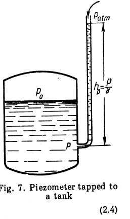
Applying Eq. (2.2) to the liquid in the piezometer, we obtain
![]()
where pab — absolute pressure of the liquid at the level of the attached end of the piezometer;
![]() atmospheric
pressure.
atmospheric
pressure.
From this, the height of the liquid in the piezometer is
![]()
where pg = gauge pressure at the same level.
Obviously, if the free surface of a still liquid is subjected to atmospheric pressure, the pressure head at any point of the liquid is equal to the depth of that point.
Pressure in fluids is often expressed numerically in terms of head according to Eq. (2.4). One atmosphere, for example, corresponds to:
![]() m
of water
m
of water
![]() m
of mercury.
m
of mercury.
If the absolute pressure in a fluid is less than atmospheric, we have a partial or complete vacuum. The magnitude of a vacuum is measured as the difference between the atmospheric and absolute pressures:
![]()
![]()
Take,
for example, a tube with a tightly fitting piston, lower one end of
it into a container with a liquid and then draw the piston up (Fig.
8). The liquid will follow the piston and rise together with it to
some height h
above
the free surface, which is subject to atmospheric
pressure. For the points immediately under the piston the deptb 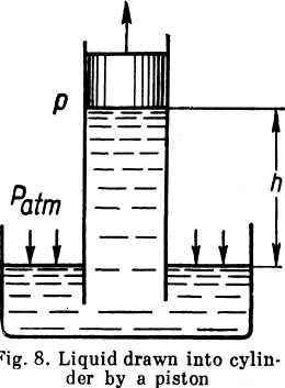 with
respect to the free surface is negative. Hence, from Eq. (2.2), the
absolute pressure in the liquid below the piston is
with
respect to the free surface is negative. Hence, from Eq. (2.2), the
absolute pressure in the liquid below the piston is
![]() .
.
and the vacuum is
![]()
![]()
As the piston rises the absolute pressure in the liquid decreases. The lower limit for the absolute pressure is zero; the maximum value of vacuum is numerically equal to atmospheric pressure. Hence, the maximum elevation of the liquid in our example, i. e., the maximum height of suction, can be found from Eq. (2.5), assuming p = 0 (or, more precisely, p = pt).
Thus, neglecting the vapour pressure pt, we have
![]()
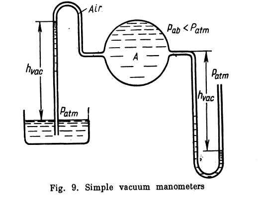
At normal atmospheric pressure (1.033 kg/cm2) the height hmax is 10.33 m for water, 13.8 m for gasoline (γ = 750 kg/m') and 0.76 m or mercury.The simplest device for measuring vacuum, or negative pressure, is a glass U-tube arranged either with one end open, like the right-hand tube in Fig. 9, or inverted with the free end submerged in a liquid, like the left-hand tube.
In laboratories, besides piezometers, various manometers and mechanical gauges are used to measure the pressure of liquids and gases.
The U-tube manometer (Fig. 10a) has the bend of a transparent tube filled with mercury or, if the pressures are small, alcohol, water or tetrabromo-ethane (δ = 2.95). If the pressure of a liquid is measured at a point M and the connecting tube is filled with the same liquid, the elevation of the manometer above M must be taken into account. Thus, the gauge pressure at point M is
![]()
A modification of the U-tube manometer in which one limb is widened (Fig. 10?>) is more convenient as only one level of the working liquid has to be read. When the diameter of the wider limb is appreciably greater than that of the tube, the level in the former can be regarded as constant. For very small pressures of gas and greater
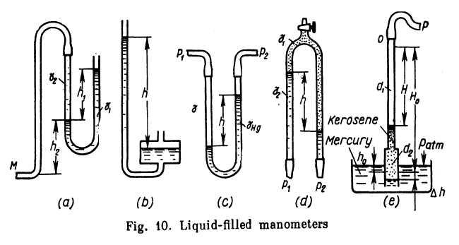
accuracy the manometer tube is inclined to the horizontal. The length of the column of liquid is inversefy proportional to the sine of the angle of inclination, the accuracy of reading improving accordincrly.
Differences of pressure at two points are measured with differential manometers, the simplest of which is the U-tube (Fig. 10c). When such a manometer, with mercury in the bend, is used to measure the difference between pressures px and p2 in a liquid of specific weight y which completely fills the connecting limbs, we have
![]()
For measuring small pressure differentials of water an inverted U-tube is used with oil or kerosene filling the upturned bend(Fig. 10d). For this case we have
![]()
The well-type manometer in Fig. lOe is designed for measuring air pressures or vacuums from about 0.1 to 0.5 atm. An alcohol or water manometer would require a very high column, making it unwieldy, while a mercury-filled manometer would be inaccurate due to the low column of mercury. This type of manometer is used in high-speed wind tunnel tests.
The well is filled with mercury and the tube with alcohol, kerosene or some other liquid. Kerosene is especially convenient due to its low rate of evaporation. A judicious selection of the diameters of the upper and lower portions of the tube (dx and d2) enables any effective specific weight yef to be obtained from the equation
![]()
where p = measured pressure or vacuum;
H = manometer reading.
The expression for yef is obtained from the following equations (see Fig. 10e):
![]()
which is the equilibrium equation for the mercury and kerosene columns at p = patm;
![]()
which is the equilibrium equation at p > patm ;and
![]()
which is the equation of volumes (the volume of the kerosene moving from the upper tube d, to the lower tube d2 is equal to the volume of the displaced mercury). Substituting and transposing, we obtain
![]()
At
d2
=
2d1,
for example,
![]()
Pressures higher than two or three atmospheres are measured with mechanical gauges of the Bourdon-tube or diaphragm type. Their action is based on the deflection of a hollow tube, diaphragm or bellows caused by the applied pressure. The deflection is transmitted through a suitable mechanism to a needle which indicates the pressure on a dial.
In aircraft systems manometers are used to measure the pressure of fuel supplied to the injectors of a gas turbine engine or to the carburettor of a reciprocating engine, the pressure of oil in the lubricating system, etc.
The most widely used in aircraft systems is the electrical manometer, as well as different types of mechanical gauges. The sensor element of an electrical manometer is a diaphragm which deflects under the applied pressure and actuates the slide of a potentiometer.